Downloaded 68 times
![ηv
V1'
x 100%
VD
1
P k
η v 1 C - C 2 x 100 %
P
1
where: V1' - volume flow rate at intake, m3/sec
VD - displacement volume, m3/sec
v - volumetric efficiency
1 - specific volume, m3/kg
v = [1 + C - C(P2/P1)1/k] x 100%
EFFICIENCY
A. Compression Efficiency
Ideal Work
η
x 100%
cn Indicated Work
B. Mechanical Efficiency
Indicated Work
η
x 100%
m Brake or Shaft Work
C. Compressor Efficiency
Ideal Work
η
x 100%
c
Brake or Shaft Work
η η η
c
cn m
EFFECTS ON OPERATING CONDITIONS
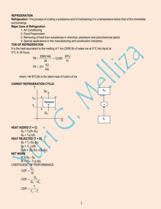
A. Effects on Increasing the Vaporizing Temperature
P
T
h
S
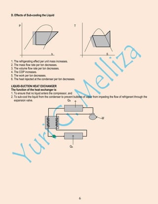
1. The refrigerating effect per unit mass increases.
2.The mass flow rate per ton decreases
3. The volume flow rate per ton decreases.
4. The COP increases.
5. The work per ton decreases.
6. The heat rejected at the condenser per ton decreases.
4](https://image.slidesharecdn.com/refrigerationsystem2-140208211835-phpapp01/85/Refrigeration-system-2-4-320.jpg)
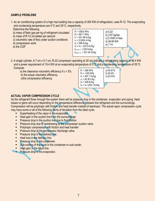
![SAMPLE PROBLEMS
1. An air cycle refrigeration system operating on a closed cycle is required to produced 50 KW
of refrigeration with a cooler pressure of 1550 KPa and a refrigerator pressure of 448 KPa.
Leaving air temperature are 25C for cooler and 5C for the refrigerator. Assuming a
theoretical cycle with isentropic compression and expansion, no clearance and no losses.
Determine;
a) the mass flow rate (0.720 kg/sec)
b) the compressor displacement (0.1283 cu.m./sec)
c) the expander displacement (0.0964 cu.m./sec
d) the COP (2.35)
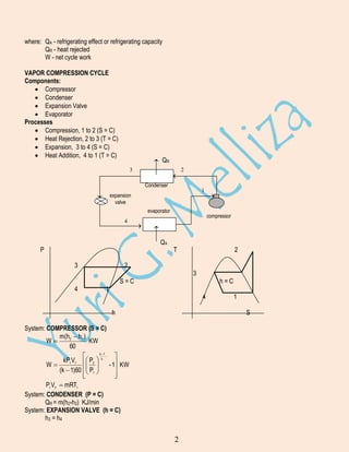
PRODUCT LOAD
Cpa
Cpb
t1
tf
m
Q1
t2
m
Q2
m
Q3
Q = Q 1 + Q2 + Q3
Q - product load
Q1 - heat to cool product from t2 to tf
Q2 - heat to freeze
Q3 - heat to cool product from tf to final storage temperature t2
Q1 = m Cpa (t1 - tf) KJ/min
Q2 = mhL KJ/min
Q3 = m Cpb (tf - t2)
where: m - mass rate in kg/min
t1 - entering temperature in C
tf - freezing temperature in C
t2 - storage temperature in C
Cpa - specific heat above freezing, KJ/kg-C or KJ/kg-K
Cpb - specific heat below freezing, KJ/kg-C or KJ/kg-K
hL - latent heat of freezing of product, KJ/kg
Q = m [Cpa (t1 - tf) + hL + Cpb (tf - t2)] KJ/min
Q
m [C pa (t 1 - t f ) hL C pb (t f - t 2 )]
211
Tons
15](https://image.slidesharecdn.com/refrigerationsystem2-140208211835-phpapp01/85/Refrigeration-system-2-15-320.jpg)
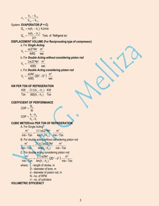
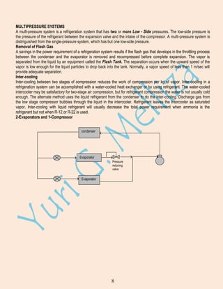
![SAMPLE PROBLEMS
1. Compute the heat to be removed from 110 kg of lean beef if it were to be cooled from 20C to 4C, after which it is
frozen and cooled to -18C. Specific heat of beef above freezing is given as 3.23 KJ/kg-C, and below freezing is
1.68 KJ/kg-C. Freezing point of beef is -2.2C, and latent heat of fusion is 233 KJ/kg.
Given: m = 110 kg Cpa = 3.23 KJ/kg-C
t1 = 20C
Cpb = 1.68 KJ/kg-C
t2 = 4C
hL = 233 KJ/kg
tf =-2.2C
t3 = -18C
Q = m[Cpa(t1 - t2) + Cpa(t2 - tf) + hL + Cpb(tf - t3)]
Q = 36 438 KJ
PREPARED BY: ENGR. YURI G. MELLIZA
16](https://image.slidesharecdn.com/refrigerationsystem2-140208211835-phpapp01/85/Refrigeration-system-2-16-320.jpg)

Refrigeration is the process of cooling a substance below the temperature of its surroundings. Major uses include air conditioning, food preservation, and industrial processes. A ton of refrigeration is the heat required to melt 1 ton of ice in 24 hours. The Carnot refrigeration cycle involves heat addition, heat rejection, and net work to transfer heat from a low temperature reservoir to a high temperature reservoir. The vapor compression cycle uses the same processes as the Carnot cycle and is commonly used in refrigeration systems. It involves compression, condensation, expansion, and evaporation. Refrigerants are circulated through the system's main components: compressor, condenser, expansion valve, and evaporator. Multi-pressure and cascade systems

![[W f stoecker]_refrigeration_and_a_ir_conditioning_(book_zz.org)](https://cdn.slidesharecdn.com/ss_thumbnails/wfstoeckerrefrigerationandairconditioningbookzz-161019162540-thumbnail.jpg?width=640&height=640&fit=bounds)


