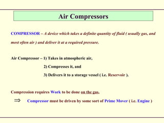
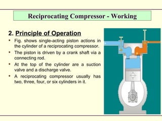
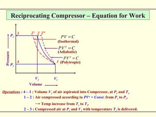
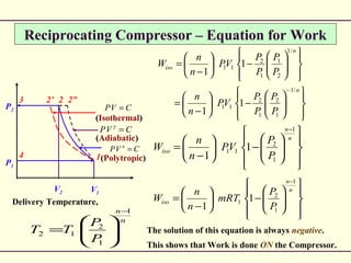
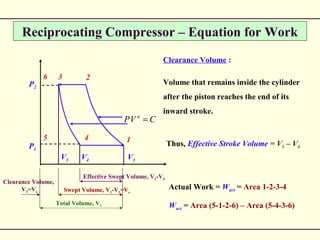
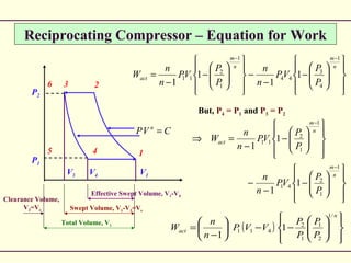
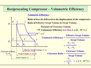
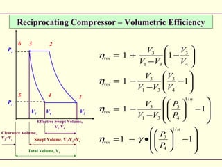
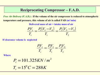
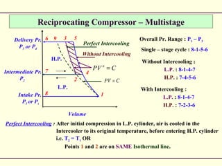
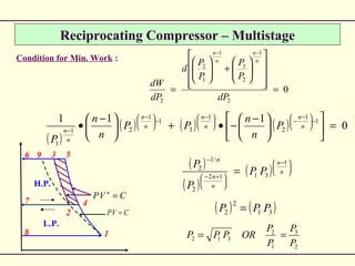
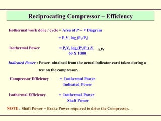
This document discusses air compressors and reciprocating compressors specifically. It defines an air compressor as a device that takes in atmospheric air, compresses it, and delivers it at higher pressure to a storage vessel. It then describes the basic components and working of a reciprocating compressor, including the polytropic process of compression, equations for calculating work done, factors affecting volumetric efficiency like clearance volume, and diagrams of the actual pressure-volume cycle including valve bounce and intake depression.
Air compressors:- One of the important device used to compress air at high pressure.
The presentation contains a detailed information about air compressors, classification of air compressors, reciprocating air compressors, rotary type, multistage/ single stage compressors. advantages and lastly application/ uses of air compressors.
Hope You like the presentation.
The ppt contains detailed study of Vapor Absorption Refrigeration System with neat sketches and description. It is well formed as per the syllabus of GTU
Refrigeration and Air Conditioning System ComponentsAjaypalsinh Barad
The ppt contains detailed study of all the components used in refrigeration and air conditioning system with neat sketches and description. It is well formed as per the syllabus of GTU
The ppt contains detailed study of refrigerants used in refrigeration and air conditioning system with description. It is well formed as per the syllabus of GTU.
Compressors are mechanical devices used for increasing the pressure of a gas. Compressors used for
producing high pressure air are called air compressors. Air is drawn from the atmosphere by suction process, which is then compressed to the required pressure and delivered to the receiver
Courier management system project report.pdfKamal Acharya
It is now-a-days very important for the people to send or receive articles like imported furniture, electronic items, gifts, business goods and the like. People depend vastly on different transport systems which mostly use the manual way of receiving and delivering the articles. There is no way to track the articles till they are received and there is no way to let the customer know what happened in transit, once he booked some articles. In such a situation, we need a system which completely computerizes the cargo activities including time to time tracking of the articles sent. This need is fulfilled by Courier Management System software which is online software for the cargo management people that enables them to receive the goods from a source and send them to a required destination and track their status from time to time.
Sachpazis:Terzaghi Bearing Capacity Estimation in simple terms with Calculati...Dr.Costas Sachpazis
Terzaghi's soil bearing capacity theory, developed by Karl Terzaghi, is a fundamental principle in geotechnical engineering used to determine the bearing capacity of shallow foundations. This theory provides a method to calculate the ultimate bearing capacity of soil, which is the maximum load per unit area that the soil can support without undergoing shear failure. The Calculation HTML Code included.
Vaccine management system project report documentation..pdfKamal Acharya
The Division of Vaccine and Immunization is facing increasing difficulty monitoring vaccines and other commodities distribution once they have been distributed from the national stores. With the introduction of new vaccines, more challenges have been anticipated with this additions posing serious threat to the already over strained vaccine supply chain system in Kenya.
Industrial Training at Shahjalal Fertilizer Company Limited (SFCL)MdTanvirMahtab2
This presentation is about the working procedure of Shahjalal Fertilizer Company Limited (SFCL). A Govt. owned Company of Bangladesh Chemical Industries Corporation under Ministry of Industries.
Immunizing Image Classifiers Against Localized Adversary Attacksgerogepatton
This paper addresses the vulnerability of deep learning models, particularly convolutional neural networks
(CNN)s, to adversarial attacks and presents a proactive training technique designed to counter them. We
introduce a novel volumization algorithm, which transforms 2D images into 3D volumetric representations.
When combined with 3D convolution and deep curriculum learning optimization (CLO), itsignificantly improves
the immunity of models against localized universal attacks by up to 40%. We evaluate our proposed approach
using contemporary CNN architectures and the modified Canadian Institute for Advanced Research (CIFAR-10
and CIFAR-100) and ImageNet Large Scale Visual Recognition Challenge (ILSVRC12) datasets, showcasing
accuracy improvements over previous techniques. The results indicate that the combination of the volumetric
input and curriculum learning holds significant promise for mitigating adversarial attacks without necessitating
adversary training.
Event Management System Vb Net Project Report.pdfKamal Acharya
In present era, the scopes of information technology growing with a very fast .We do not see any are untouched from this industry. The scope of information technology has become wider includes: Business and industry. Household Business, Communication, Education, Entertainment, Science, Medicine, Engineering, Distance Learning, Weather Forecasting. Carrier Searching and so on.
My project named “Event Management System” is software that store and maintained all events coordinated in college. It also helpful to print related reports. My project will help to record the events coordinated by faculties with their Name, Event subject, date & details in an efficient & effective ways.
In my system we have to make a system by which a user can record all events coordinated by a particular faculty. In our proposed system some more featured are added which differs it from the existing system such as security.
Quality defects in TMT Bars, Possible causes and Potential Solutions.PrashantGoswami42
Maintaining high-quality standards in the production of TMT bars is crucial for ensuring structural integrity in construction. Addressing common defects through careful monitoring, standardized processes, and advanced technology can significantly improve the quality of TMT bars. Continuous training and adherence to quality control measures will also play a pivotal role in minimizing these defects.
Cosmetic shop management system project report.pdfKamal Acharya
Buying new cosmetic products is difficult. It can even be scary for those who have sensitive skin and are prone to skin trouble. The information needed to alleviate this problem is on the back of each product, but it's thought to interpret those ingredient lists unless you have a background in chemistry.
Instead of buying and hoping for the best, we can use data science to help us predict which products may be good fits for us. It includes various function programs to do the above mentioned tasks.
Data file handling has been effectively used in the program.
The automated cosmetic shop management system should deal with the automation of general workflow and administration process of the shop. The main processes of the system focus on customer's request where the system is able to search the most appropriate products and deliver it to the customers. It should help the employees to quickly identify the list of cosmetic product that have reached the minimum quantity and also keep a track of expired date for each cosmetic product. It should help the employees to find the rack number in which the product is placed.It is also Faster and more efficient way.
Forklift Classes Overview by Intella PartsIntella Parts
Discover the different forklift classes and their specific applications. Learn how to choose the right forklift for your needs to ensure safety, efficiency, and compliance in your operations.
For more technical information, visit our website https://intellaparts.com
Automobile Management System Project Report.pdfKamal Acharya
The proposed project is developed to manage the automobile in the automobile dealer company. The main module in this project is login, automobile management, customer management, sales, complaints and reports. The first module is the login. The automobile showroom owner should login to the project for usage. The username and password are verified and if it is correct, next form opens. If the username and password are not correct, it shows the error message.
When a customer search for a automobile, if the automobile is available, they will be taken to a page that shows the details of the automobile including automobile name, automobile ID, quantity, price etc. “Automobile Management System” is useful for maintaining automobiles, customers effectively and hence helps for establishing good relation between customer and automobile organization. It contains various customized modules for effectively maintaining automobiles and stock information accurately and safely.
When the automobile is sold to the customer, stock will be reduced automatically. When a new purchase is made, stock will be increased automatically. While selecting automobiles for sale, the proposed software will automatically check for total number of available stock of that particular item, if the total stock of that particular item is less than 5, software will notify the user to purchase the particular item.
Also when the user tries to sale items which are not in stock, the system will prompt the user that the stock is not enough. Customers of this system can search for a automobile; can purchase a automobile easily by selecting fast. On the other hand the stock of automobiles can be maintained perfectly by the automobile shop manager overcoming the drawbacks of existing system.
Water scarcity is the lack of fresh water resources to meet the standard water demand. There are two type of water scarcity. One is physical. The other is economic water scarcity.
1. ME 6404 – THERMAL ENGINEERING
UNIT – IV – Air Compressor
by
A.GANESAN
Assistant Professor
Dept. of Mechanical Engg
Kamaraj College of Engg & Tech, Virudhunagar
2. Air Compressors
COMPRESSOR – A device which takes a definite quantity of fluid ( usually gas, and
most often air ) and deliver it at a required pressure.
Air Compressor – 1) Takes in atmospheric air,
2) Compresses it, and
3) Delivers it to a storage vessel ( i.e. Reservoir ).
Compression requires Work to be done on the gas,
Compressor must be driven by some sort of Prime Mover ( i.e. Engine )⇒
4. Reciprocating Compressor - Working
2. Principle of Operation
Fig. shows single-acting piston actions in
the cylinder of a reciprocating compressor.
The piston is driven by a crank shaft via a
connecting rod.
At the top of the cylinder are a suction
valve and a discharge valve.
A reciprocating compressor usually has
two, three, four, or six cylinders in it.
6. Reciprocating Compressor – Equation for Work
Volume
Pressure
P1
P2
V1
V2
3 2 2”2’
4 1 (Polytropic)
(Adiabatic)
(Isothermal)
CVP n
=
CVP =γ
CVP =
Operations : 4 – 1 : Volume V1 of air aspirated into Compressor, at P1 and T1.
1 – 2 : Air compressed according to PVn
= Const. from P1 to P2.
→ Temp increase from T1 to T2.
2 – 3 : Compressed air at P2 and V2 with temperature T2 is delivered.
7. Reciprocating Compressor – Equation for Work
During Compression, due to the excess temperature above surrounding, the air will
exchange the heat to the surrounding.
⇒ Compression Index, n is always less than γ, the adiabatic index.
As Compressor is a work consuming device, every effort is desired to reduce the work.
Work done = Area under P-V curve
⇒ 1 – 2” : Adiabatic Compression = Max. Work.
⇒ 1 – 2 : Polytropic Compression
⇒ 1 – 2’ : Isothermal Compression = Min. Work.
8. Reciprocating Compressor – Equation for Work
Thus, comparison between the Isothermal Work and the Actual Work is important.
Isothermal Efficiency, ηiso =
Isothermal Work
Actual Work
Thus, more the Isothermal Efficiency, more the actual compression approaches to the
Isothermal Compression.
P1
P2
V1
V2
3 2 2”2’
4 1(Polytropic)
(Adiabatic)
(Isothermal)
CVP n
=
CVP =γ
CVP =
Actual Work = Wact = Area 4-1-2-3-4
Wact = Area (4-1) – Area (1-2) – Area (2-3)
( )
( )
−
−
+−=
−
−
−−=
−
−
−
−=
1
1
1
2211
2211
1122
2211
22
1122
11
n
VPVP
VPVP
n
VPVP
VPVP
VP
n
VPVP
VP
11. Reciprocating Compressor – Equation for Work
P1
P2
V1V4
6 2
5 1
CVP n
=
3
4
V3
Effective Swept Volume, V1-V4
Swept Volume, V1-V3=Vs
Total Volume, V1
Clearance Volume,
V3=Vc
Clearance Volume :
Volume that remains inside the cylinder
after the piston reaches the end of its
inward stroke.
Thus, Effective Stroke Volume = V1 – V4
Actual Work = Wact = Area 1-2-3-4
Wact = Area (5-1-2-6) – Area (5-4-3-6)
12. Reciprocating Compressor – Equation for Work
−
−
−
−
−
=⇒
−
−
n
m
n
m
act
P
P
VP
n
n
P
P
VP
n
n
W
1
1
2
41
1
1
2
11
1
1
1
1
( )
−−
−
=
n
act
P
P
P
P
VVP
n
n
W
/1
2
1
1
2
411 1
1
−
−
−
−
−
=
−−
n
m
n
m
act
P
P
VP
n
n
P
P
VP
n
n
W
1
4
3
44
1
1
2
11 1
1
1
1
P1
P2
V1V4
6 2
5 1
CVP n
=
3
4
V3
Effective Swept Volume, V1-V4
Swept Volume, V1-V3=Vs
Total Volume, V1
Clearance Volume,
V3=Vc
But, P4 = P1 and P3 = P2
13. Reciprocating Compressor – Volumetric Efficiency
Volumetric Efficiency :
Ratio of free air delivered to the displacement of the compressor.
Ratio of Effective Swept Volume to Swept Volume.
Volumetric Efficiency =
Effective Swept Volume
Swept Volume
V1 – V4
V1 – V3
=
Vc
Vs
= = γ
Clearance Volume
Swept Volume
Clearance Ratio =
Presence of Clearance Volume
Volumetric Efficiency less than 1. ( 60 – 85 % )⇒
P1
P2
V1V4
6 2
5 1
CVP n
=
3
4
V3
Effective Swept Volume, V1-V4
Swept Volume, V1-V3=Vs
Total Volume, V1
Clearance Volume,
V3=Vc
( 4 – 10 % )
14. Reciprocating Compressor – Volumetric Efficiency
⇒↑ Pr. Ratio ↑ Effect of Clearance Volume
….Clearance air expansion through greater volume before intake
⇒
⇒
Cylinder bore and stroke is fixed.
Effective Swept Volume (V1 – V4) ↓ with ↑ Pr. Ratio
↓ Volumetric Efficiency⇒
⇒
( ) ( )
( ) ( ) ( )
( ) ( )
( ) ( ) 3
4
31
3
31
3
3
3
31
4
31
3
31
4
31
3
31
4331
31
41
1
1
1
V
V
VV
V
VV
V
V
V
VV
V
VV
V
VV
V
VV
V
VV
VVVV
VV
VV
vol
•
−
−
−
+=
•
−
−
−
+=
−
−
−
+=
−
−+−
=
−
−
=η
P1
P2
V1V4
6 2
5 1
3
4
V3
Effective Swept Volume,
V1-V4
Swept Volume, V1-V3=Vs
Total Volume, V1
Clearance Volume,
V3=Vc
15. Reciprocating Compressor – Volumetric Efficiency
−
•−=
−
−
−=
−
−
−=
−
−
+=
11
11
11
11
/1
4
3
/1
4
3
31
3
4
3
31
3
4
3
31
3
n
vol
n
vol
vol
vol
P
P
P
P
VV
V
V
V
VV
V
V
V
VV
V
γη
η
η
η
P1
P2
V1V4
6 2
5 1
3
4
V3
Effective Swept Volume,
V1-V4
Swept Volume, V1-V3=Vs
Total Volume, V1
Clearance Volume,
V3=Vc
16. Reciprocating Compressor – Actual P-V Diagram
P1
P2
2
1
3
4
Valve Bounce
Intake Depression
Atmospheric Pressure
Receiver Pressure 1-2-3-4-1 : Theoretical P-V Diagram.
At 4, inlet valve does not open due to :
1. There must be a pressure difference across the valve to open.
2. Inlet valve inertia.
Pr. Drop continues till sufficient level
for valve to force its seat.
Some valve bounce is set (wavy line).
Eventually, the pressure sets down at a level lower
than atmospheric pressure. This negative pressure
difference is known as Intake Depression.
Similar situation appears at 2, i.e. at the start of the delivery.
Pressure rise, followed by valve bounce and then pressure settles at a level higher than
the delivery pressure level.
Air delivery to a tank / receiver, hence, generally known as Receiver Pressure.
17. Reciprocating Compressor – F.A.D.
Free Air Delivery (F.A.D.) : If the volume of the air compressor is reduced to atmospheric
temperature and pressure, this volume of air is called FAD (m3
/min)
Delivered mass of air = intake mass of air
( ) ( )
2
322
1
411
T
VVP
T
VVP
T
VP
t
tt −
=
−
=
If clearance volume is neglected
Where
KCT
mKNP
t
t
28815
/325.101
0
2
==
=
2
22
1
11
T
VP
T
VP
T
VP
t
tt
==
18. Reciprocating Compressor – Multistage
High Pressure required by Single – Stage :
⇒ 1. Requires heavy working parts.
2. Has to accommodate high pressure ratios.
3. Increased balancing problems.
4. High Torque fluctuations.
5. Requires heavy Flywheel installations.
This demands for MULTI – STAGING…!!
19. Reciprocating Compressor – Multistage
Series arrangement of cylinders, in which the compressed air from earlier cylinder
(i.e. discharge) becomes the intake air for the next cylinder (i.e. inlet).
Intercooler :
Compressed air is cooled
between cylinders.
L.P. = Low Pressure
I.P. = Intermediate
Pressure
H.P. = High Pressure
L.P.
Cylinder
I.P.
Cylinder
H.P.
Cylinder
Intercooler
Intercooler
Air Intake
Air Delivery
20. Reciprocating Compressor – Multistage
Intake Pr.
P1 or Ps
Delivery Pr.
P3 or Pd
3
2
9 5
4
1
CVP n
=
8
7
6
Intermediate Pr.
P2 CVP =
Without Intercooling
Perfect Intercooling
L.P.
H.P.
Volume
Overall Pr. Range : P1 – P3
Single – stage cycle : 8-1-5-6
Without Intercooling :
L.P. : 8-1-4-7
H.P. : 7-4-5-6
With Intercooling :
L.P. : 8-1-4-7
H.P. : 7-2-3-6
Perfect Intercooling : After initial compression in L.P. cylinder, air is cooled in the
Intercooler to its original temperature, before entering H.P. cylinder
i.e. T2 = T1 OR
Points 1 and 2 are on SAME Isothermal line.
21. Reciprocating Compressor – Multistage
Ideal Conditions for Multi – Stage Compressors :
A. Single – Stage Compressor :
CVP =
3
2
9 5
4
1
CVP n
=
8
7
6
L.P.
H.P.
Single – stage cycle : 8-1-5-6
−
−
=
−1
1
5
11 1
1
n
n
P
P
VP
n
n
W
Delivery Temperature,
n
n
P
P
TT
1
1
5
15
−
=
22. Reciprocating Compressor – Multistage
CVP =
3
2
9 5
4
1
CVP n
=
8
7
6
L.P.
H.P.
B. Two – Stage Compressor (Without Intercooling) :
Without Intercooling :
L.P. : 8-1-4-7
H.P. : 7-4-5-6
−
−
+
−
−
=
−
−
n
n
n
n
P
P
VP
n
n
P
P
VP
n
n
W
1
4
5
44
1
1
4
11
1
1
1
1
This is SAME as that of Work done in Single – Stage.
Delivery Temperature also remains SAME.
Without Intercooling ⇒
23. Reciprocating Compressor – Multistage
CVP =
3
2
9 5
4
1
CVP n
=
8
7
6
L.P.
H.P.
C. Two – Stage Compressor (With Perfect Intercooling) :
With Intercooling :
L.P. : 8-1-4-7-8
H.P. : 7-2-3-6-7
−
−
+
−
−
=
−
−
n
n
n
n
P
P
VP
n
n
P
P
VP
n
n
W
1
2
3
22
1
1
4
11
1
1
1
1
Delivery Temperature,
12
1
2
3
1
1
2
3
23 , TTas
P
P
T
P
P
TT
n
n
n
n
=
=
=
−−
24. Reciprocating Compressor – Multistage
CVP =
3
2
9 5
4
1
CVP n
=
8
7
6
L.P.
H.P.
C. Two – Stage Compressor (With Perfect Intercooling) :
With Intercooling :
L.P. : 8-1-4-7-8
H.P. : 7-2-3-6-7
−
−
−
=
−−
n
n
n
n
P
P
P
P
VP
n
n
W
1
2
3
1
1
2
11 2
1
Now, T2 = T1
P2V2 = P1V1
Also P4 = P2
Shaded Area 2-4-5-3-2 : Work Saving due to Intercooler…!!
25. Reciprocating Compressor – Multistage
Condition for Min. Work :
CVP =
3
2
9 5
4
1
CVP n
=
8
7
6
L.P.
H.P.
Intermediate Pr. P2 → P1 : Area 2-4-5-3-2 → 0
Intermediate Pr. P2 → P3 : Area 2-4-5-3-2 → 0
⇒There is an Optimum P2 for which Area 2-4-5-3-2
is maximum,
i.e. Work is minimum…!!
−
−
−
=
−−
n
n
n
n
P
P
P
P
VP
n
n
W
1
2
3
1
1
2
11 2
1
0
2
1
2
3
1
1
2
2
=
+
=
−−
dP
P
P
P
P
d
dP
dW
n
n
n
n
For min. Work,
26. Reciprocating Compressor – Multistage
Condition for Min. Work :
( )
( ) ( ) ( ) 0
111 1
1
2
1
3
1
1
21
1
=
−
−•+
−
•
−
−
−
−
−
−
−
n
n
n
n
n
n
n
n
P
n
n
PP
n
n
P
0
2
1
2
3
1
1
2
2
=
+
=
−−
dP
P
P
P
P
d
dP
dW
n
n
n
n
( )
( )
( )
−
+−
−
= n
n
n
n
n
PP
P
P 1
3112
2
/1
2
( ) ( )31
2
2 PPP =
2
3
1
2
312
P
P
P
P
ORPPP ==
CVP =
3
2
9 5
4
1
CVP n
=
8
7
6
L.P.
H.P.
27. Reciprocating Compressor – Multistage
P2 obtained with this condition (Pr. Ratio per stage is equal) is the Ideal Intermediate
Pr. Which, with Perfect Intercooling, gives Minimum Work, Wmin.
( )
−
−
=
−
n
n
P
PP
VP
n
n
W
1
1
2/1
31
11 1
1
2
−
−
=
−
n
n
P
P
VP
n
n
W
1
1
2
11 1
1
2
⇒
−
−
=
−
n
n
P
P
VP
n
n
W
2
1
1
3
11 1
1
2
Equal Work per cylinder…!!⇒
28. Reciprocating Compressor – Efficiency
Isothermal work done / cycle = Area of P – V Diagram
= P1V1 loge(P2/P1)
Isothermal Power = P1V1 loge(P2/P1) N
60 X 1000
kW
Indicated Power : Power obtained from the actual indicator card taken during a
test on the compressor.
Compressor Efficiency = Isothermal Power
Indicated Power
Isothermal Efficiency = Isothermal Power
Shaft Power
NOTE : Shaft Power = Brake Power required to drive the Compressor.
29. Reciprocating Compressor – Efficiency
Adiabatic Efficiency : Ratio of Power required to drive the Compressor; compared
with the area of the hypothetical Indicator Diagram; assuming
Adiabatic Compression.
CompressorthedrivetorequiredPowerBrake
P
P
VP
adiabatic
−
−
=
−
γ
γ
γ
γ
η
1
1
2
11 1
1
Mechanical Efficiency : Ratio of mechanical output to mechanical input.
Mechanical Efficiency, ηmech = Indicated Power
Shaft Power
30. Reciprocating Compressor – Efficiency
How to Increase Isothermal Efficiency ?
A. Spray Injection : Assimilation of water into the compressor cylinder towards the
compression stroke.
Object is to cool the air for next operation.
Demerits : 1. Requires special gear for injection.
2. Injected water interferes with the cylinder lubrication.
3. Damage to cylinder walls and valves.
4. Water must be separated before delivery of air.
B. Water Jacketing : Circulating water around the cylinder to help for cooling the
air during compression.
31. Reciprocating Compressor – Efficiency
How to Increase Isothermal Efficiency ?
C. Inter – Cooling : For high speed and high Pr. Ratio compressors.
Compressed air from earlier stage is cooled to its original
temperature before passing it to the next stage.
D. External Fins : For small capacity compressors, fins on external surfaces are useful.
E. Cylinder Proportions : Short stroke and large bore provides much greater surface
for cooling.
Cylinder head surface is far more effective than barrel
surface.
32. Reciprocating Compressor – Efficiency
Clearance Volume : Consists of two spaces.
1. Space between cylinder end & the piston to allow for wear.
2. Space for reception of valves.
High – class H.P. compressors : Clearance Vol. = 3 % of Swept Vol.
: Lead (Pb) fuse wire used to measure the gap
between
cylinder end and piston.Low – grade L.P. compressors : Clearance Vol. = 6 % of Swept Vol.
: Flattened ball of putty used to measure the gap
between cylinder end and piston.
Effect of Clearance Vol. :
Vol. taken in per stroke < Swept Vol. ↑ Size of compressor
↑ Power to drive compressor.
⇒
33. P1
P2
V1V4
6 2
5 1
3
4
V3
Effective Swept Volume,
V1-V4
Swept Volume, V1-V4=Vs
Total Volume, V1
Clearance Volume,
V3=Vc
Reciprocating Compressor – Work Done
−
−
−
−
−
=
−−
n
n
n
n
P
P
VP
n
n
P
P
VP
n
n
W
1
4
3
44
1
1
2
11 1
1
1
1
Assumption : Compression and Expansion follow same Law.
Work / cycle = Area 1-2-3-4-1
P3 = P2 and P4 = P1
−
−
=
−−
−
=
−
−
n
n
a
n
n
P
P
VP
n
n
P
P
VVP
n
n
W
1
1
2
1
1
1
2
411
1
1
1)(
1
34. P1
P2
V1V4
6 2
5 1
3
4
V3
Effective Swept Volume,
V1-V4
Swept Volume, V1-V4=Vs
Total Volume, V1
Clearance Volume,
V3=Vc
Reciprocating Compressor – Work Done
−
−
=
−
n
n
P
P
TRm
n
n
W
1
1
2
11 1
1
m1 is the actual mass of air delivered.
Work done / kg of air delivered :
−
−
=
−
n
n
P
P
TR
n
n
W
1
1
2
1 1
1