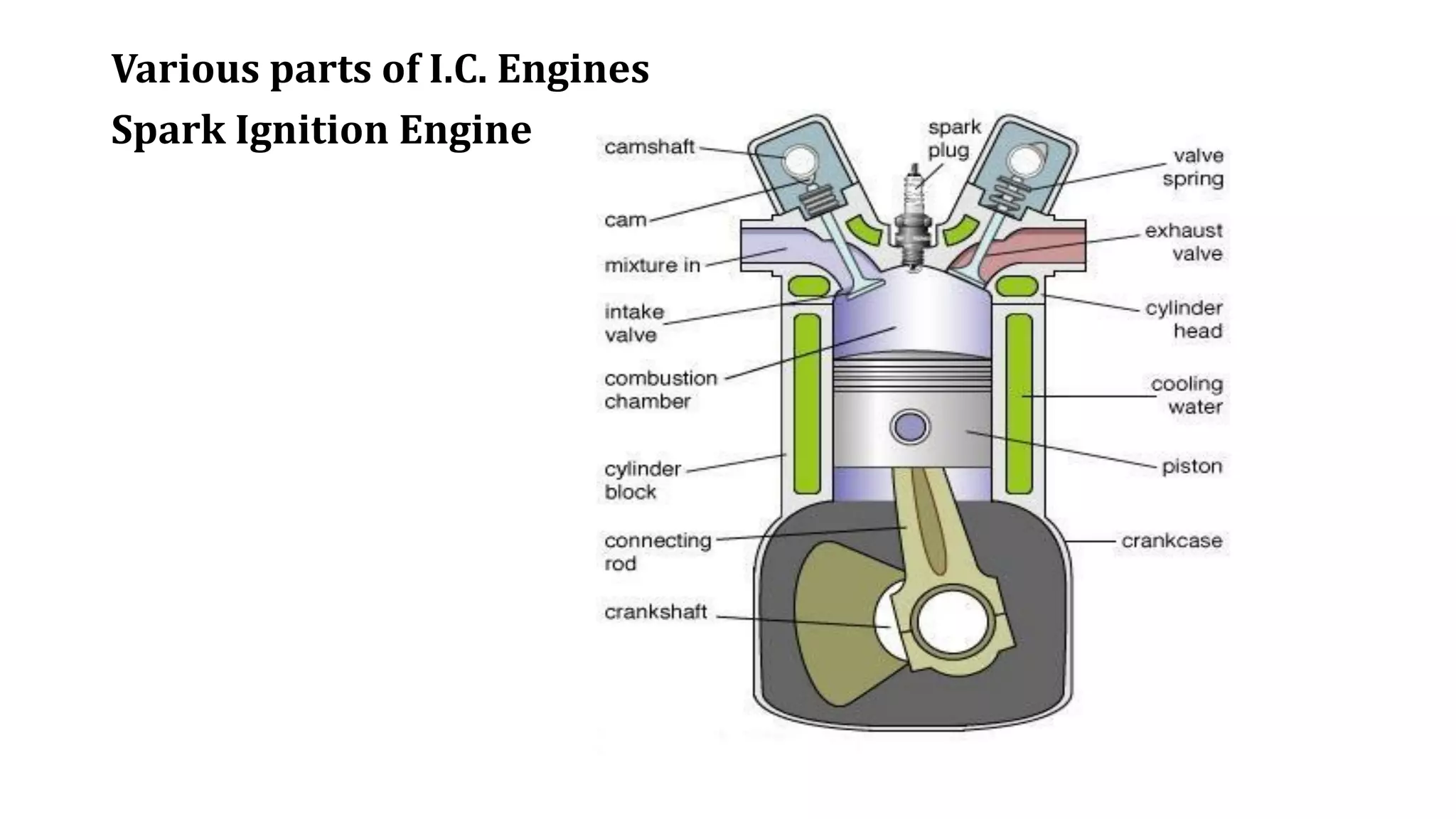
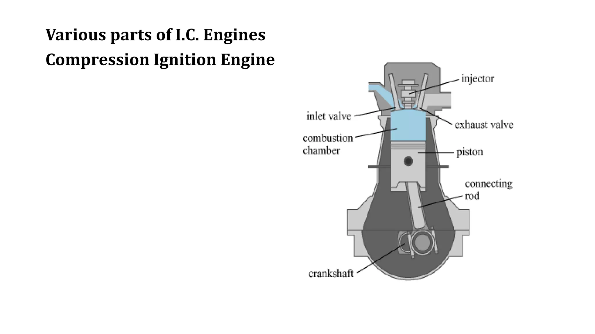
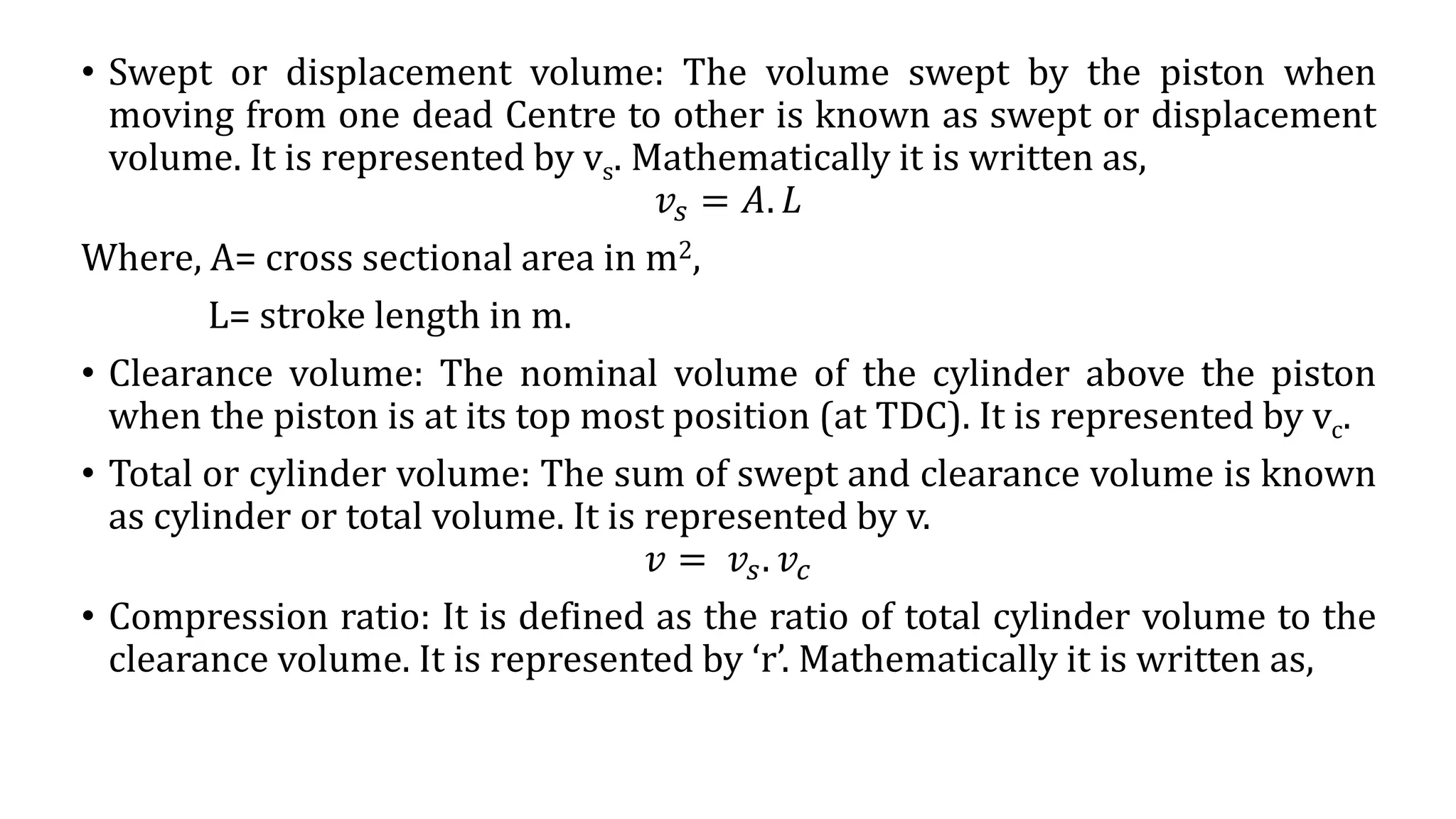
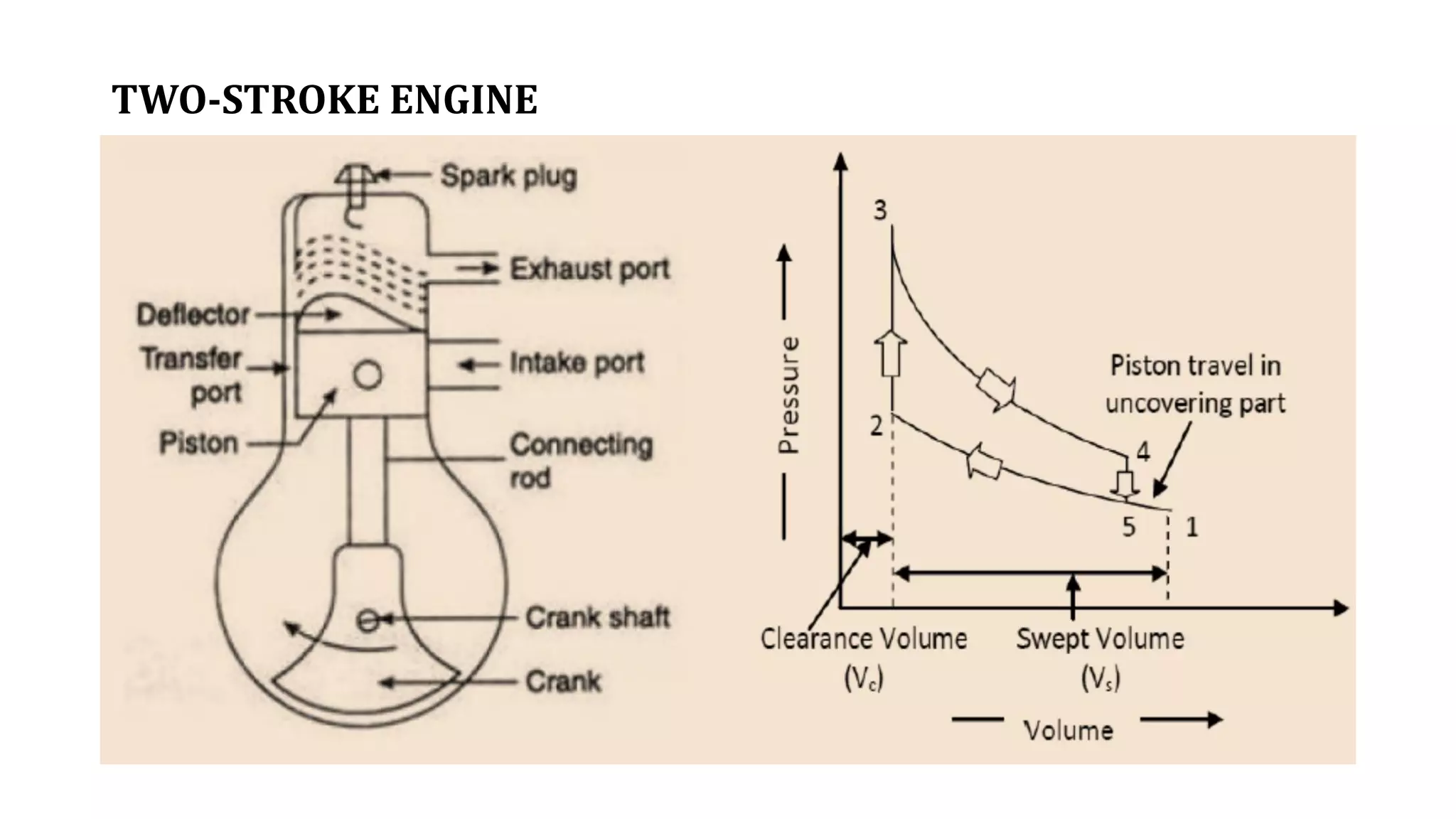
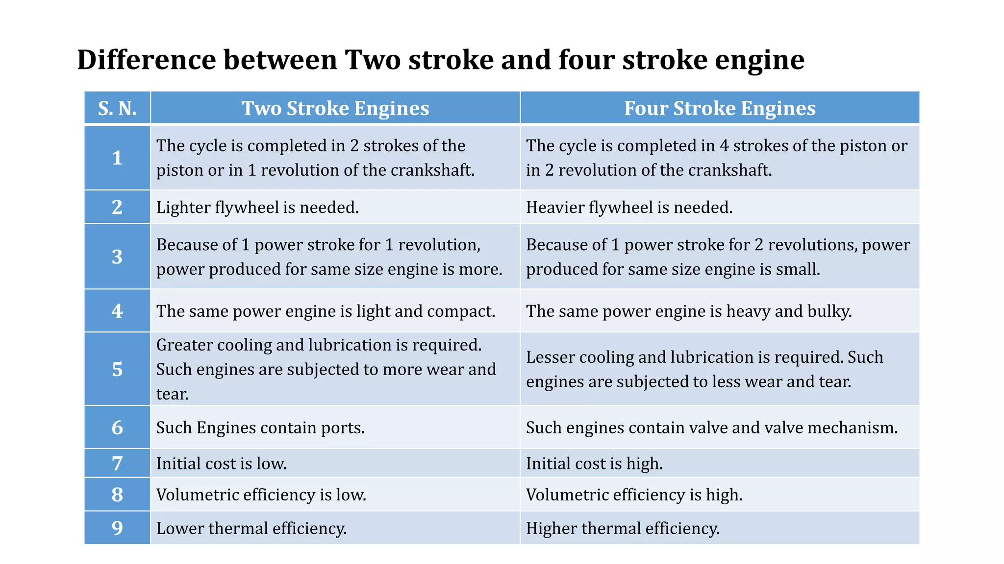
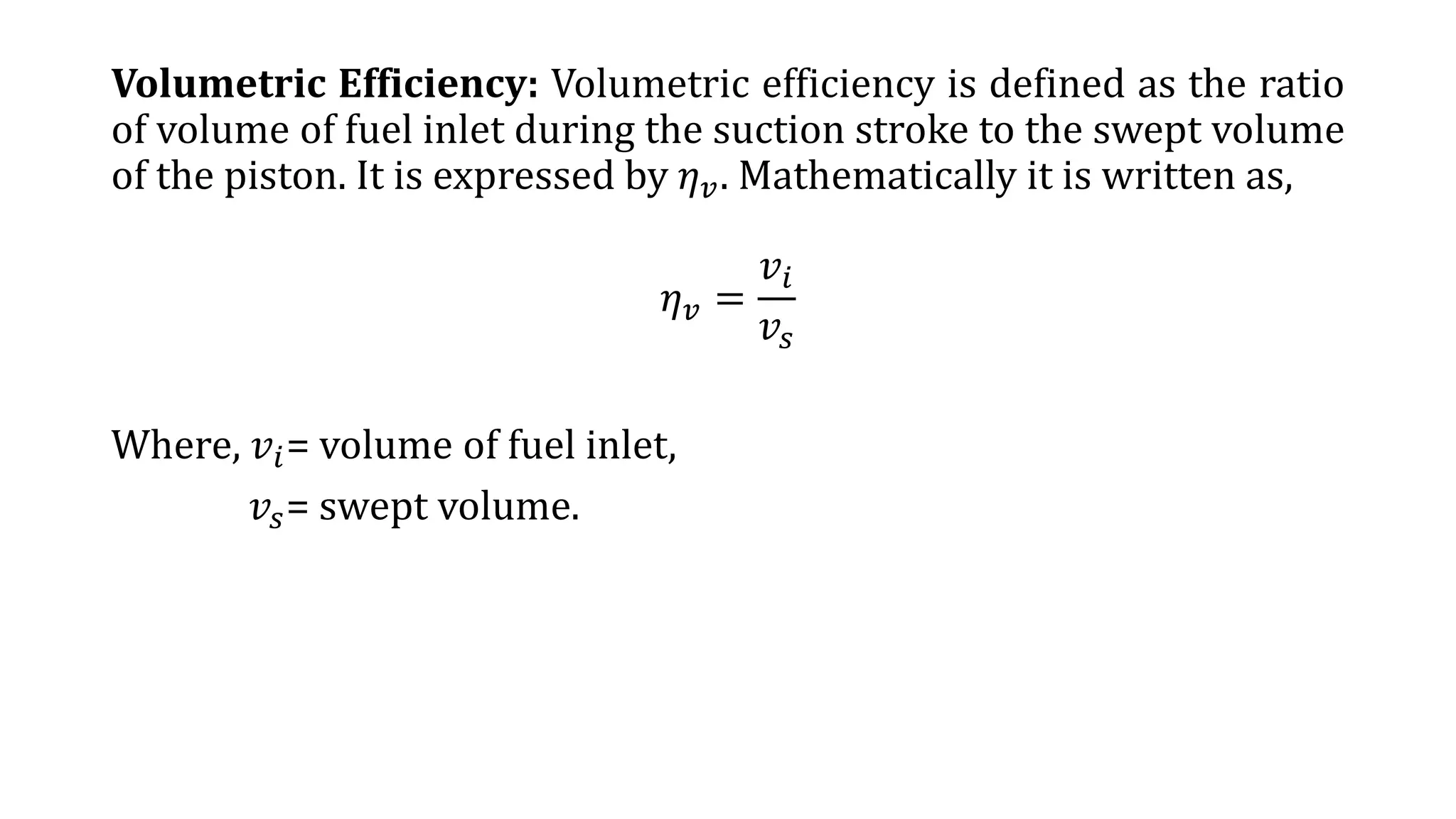
The document discusses internal combustion engines. It defines an internal combustion engine as a heat engine that converts thermal energy from fuel into mechanical work. It then classifies internal combustion engines in several ways such as by design, working cycle, number of strokes, fuel used, and other factors. The key parts of internal combustion engines like the cylinder, piston, valves are also defined. Important terminology used in internal combustion engines such as cylinder bore, stroke, swept volume, compression ratio are explained. The workings of different types of internal combustion engines such as spark ignition engines, compression ignition engines, and 2-stroke engines are outlined. Their differences and various engine efficiencies are also compared.
Definition of Supercharging ,
Effect of Supercharging ,
Need of Supercharging ,
Types of Supercharging
1) Centrifugal Supercharger
2) Rootes Supercharger
3) Vane Supercharger ,
Advantages & Disadvantages of Supercharging
in this presentation , the different engine inefficiencies has been discussed including all sort of friction losses which affects the brake power of the engine. It includes volumetric efficiency, thermal efficiency, IMEP, BMEP, brake power etc.
PPT describes the engine performance parameters of the I.C. engine.
Engine performance is an indication of the degree of success of the engine performs its assigned task, i.e. the conversion of the chemical energy contained in the fuel into the useful mechanical work. The engine performance is indicated by the term efficiency, η. Five important engine efficiencies and other related engine performance parameters are:
Power
Indicated Thermal Efficiency (ηith)
Brake Thermal Efficiency (ηbth)
Mechanical Efficiency (ηm)
Volumetric Efficiency (ηv)
Relative Efficiency or Efficiency Ratio (ηrel)
Mean Effective Pressure (Pm)
Specific Fuel Consumption (sfc)
Fuel-Air or Air-Fuel Ratio (F/A or A/F)
Calorific Value (CV)
Power:-
The main purpose of running an engine is to obtain mechanical power.
Brake Power (B.P.)
The power developed by an Engine at the output shaft is called the brake power.
Brake Power= Brake Workdone/Time
B.P.=BWD/sec.
Indicated power (I.P.)
The total power developed by Combustion of fuel in the combustion chamber is called indicated power.
Indicated Power= Indicated Workdone/Time
I.P.=IWD/sec.
Frictional Power (F.P.)
The difference between I.P. and B.P. is called frictional power (f.p.).
FP = IP – BP
Thermal Efficiency (ηth)
Thermal efficiency is the ratio of Power to energy supplied by the fuel.
ηth= Power/ Energy
In I.C. Engine, thermal efficiency can be classified into two categories i.e.
Indicated Thermal Efficiency (ηith)
Indicated thermal efficiency is the ratio of indicated power to the heat supplied or added.
ηith= IP/Qs
2. Brake Thermal Efficiency (ηith)
Brake Thermal Efficiency is the ratio of brake power to the heat supplied or added.
ηbth= BP/Qs
Volumetric Efficiency (ηv)
This is one of the most important parameters which decide the performance of four-stroke engines. Four stoke engines have distinct suction stoke, volumetric efficiency indicates the breathing ability of the engine.
Volumetric efficiency is defined as the ratio of actual flow rate of air into the intake system to rate at which the volume is displaced by the system.
ηv= (푚 ̇"a/a" )/(푉푑푖푠푝푎푐푒푑 푋 푁/2)
"a"= Inlet density is taken atmospheric air density
N= Number of the cylinder in use
A steam turbine is a prime mover in which the potential energy of the steam is transformed into kinetic energy and later in its turn is transformed into the mechanical energy of rotation of the turbine shaft
4 stroke petrol engine,2 stroke petrol engine,parts of engine,classification of engines,indicated power,brake power,thermal efficiency,mechanical efficiency,break thermal efficiency
E-Commerce: von der Goldgrube zum knallharten Business. Das Wachstum ist ungebremst, doch der Markt wird seine Opfer fordern - erste Marktbereinigungen stehen an. In einem kurzen Rückblick auf 2012 nennt Thomas Lang Gewinner- und Verlierer beim Namen. Doch welches sind die grössten Herausforderungen 2013 denen sich PurePlayer, Multi-Channel-Händler oder Stationäre stellen müssen. Welche Trends haben 2013 Relevanz und wie setzt man diese konkret für den eigenen Erfolg ein. Und welche Trends gehören ins Reich der Märchen.
Vorhersagen 2012 im Reality-Check – ein kurzer Rückblick
Gewinner & Verlierer – Namen & Zahlen
Trends & Best Practices die auf jede E-Commerce Agenda 2013 gehören
Was man aus strategischen Fehlentscheiden der Chefetage und deren analogen Beratern lernen kann
Technische Revolutionen die den elektronischen Handel weiter beschleunigen werden
IC engine full chapter ppt
IC engine full chapter pdf
Engineering student notes
Engineering notes
IC engine notes
IC engine full chapter
Petrol engine
Diesel engine
IC engine fuel engineering pdf
Thermodynamics book pdf
Thermal engineering 1 pdf
Thermal engineering 2 pdf
Internal combustion engine
External combustion engine
Spark ignition
Compression ignition
Engine, classification of heat engine, classification of IC engine, component of IC engine, four stroke engine and 2- stroke engine, petrol and diesel engine, comparisons, terminology related to engine
Event Management System Vb Net Project Report.pdfKamal Acharya
In present era, the scopes of information technology growing with a very fast .We do not see any are untouched from this industry. The scope of information technology has become wider includes: Business and industry. Household Business, Communication, Education, Entertainment, Science, Medicine, Engineering, Distance Learning, Weather Forecasting. Carrier Searching and so on.
My project named “Event Management System” is software that store and maintained all events coordinated in college. It also helpful to print related reports. My project will help to record the events coordinated by faculties with their Name, Event subject, date & details in an efficient & effective ways.
In my system we have to make a system by which a user can record all events coordinated by a particular faculty. In our proposed system some more featured are added which differs it from the existing system such as security.
Courier management system project report.pdfKamal Acharya
It is now-a-days very important for the people to send or receive articles like imported furniture, electronic items, gifts, business goods and the like. People depend vastly on different transport systems which mostly use the manual way of receiving and delivering the articles. There is no way to track the articles till they are received and there is no way to let the customer know what happened in transit, once he booked some articles. In such a situation, we need a system which completely computerizes the cargo activities including time to time tracking of the articles sent. This need is fulfilled by Courier Management System software which is online software for the cargo management people that enables them to receive the goods from a source and send them to a required destination and track their status from time to time.
Automobile Management System Project Report.pdfKamal Acharya
The proposed project is developed to manage the automobile in the automobile dealer company. The main module in this project is login, automobile management, customer management, sales, complaints and reports. The first module is the login. The automobile showroom owner should login to the project for usage. The username and password are verified and if it is correct, next form opens. If the username and password are not correct, it shows the error message.
When a customer search for a automobile, if the automobile is available, they will be taken to a page that shows the details of the automobile including automobile name, automobile ID, quantity, price etc. “Automobile Management System” is useful for maintaining automobiles, customers effectively and hence helps for establishing good relation between customer and automobile organization. It contains various customized modules for effectively maintaining automobiles and stock information accurately and safely.
When the automobile is sold to the customer, stock will be reduced automatically. When a new purchase is made, stock will be increased automatically. While selecting automobiles for sale, the proposed software will automatically check for total number of available stock of that particular item, if the total stock of that particular item is less than 5, software will notify the user to purchase the particular item.
Also when the user tries to sale items which are not in stock, the system will prompt the user that the stock is not enough. Customers of this system can search for a automobile; can purchase a automobile easily by selecting fast. On the other hand the stock of automobiles can be maintained perfectly by the automobile shop manager overcoming the drawbacks of existing system.
Vaccine management system project report documentation..pdfKamal Acharya
The Division of Vaccine and Immunization is facing increasing difficulty monitoring vaccines and other commodities distribution once they have been distributed from the national stores. With the introduction of new vaccines, more challenges have been anticipated with this additions posing serious threat to the already over strained vaccine supply chain system in Kenya.
Water scarcity is the lack of fresh water resources to meet the standard water demand. There are two type of water scarcity. One is physical. The other is economic water scarcity.
About
Indigenized remote control interface card suitable for MAFI system CCR equipment. Compatible for IDM8000 CCR. Backplane mounted serial and TCP/Ethernet communication module for CCR remote access. IDM 8000 CCR remote control on serial and TCP protocol.
• Remote control: Parallel or serial interface.
• Compatible with MAFI CCR system.
• Compatible with IDM8000 CCR.
• Compatible with Backplane mount serial communication.
• Compatible with commercial and Defence aviation CCR system.
• Remote control system for accessing CCR and allied system over serial or TCP.
• Indigenized local Support/presence in India.
• Easy in configuration using DIP switches.
Technical Specifications
Indigenized remote control interface card suitable for MAFI system CCR equipment. Compatible for IDM8000 CCR. Backplane mounted serial and TCP/Ethernet communication module for CCR remote access. IDM 8000 CCR remote control on serial and TCP protocol.
Key Features
Indigenized remote control interface card suitable for MAFI system CCR equipment. Compatible for IDM8000 CCR. Backplane mounted serial and TCP/Ethernet communication module for CCR remote access. IDM 8000 CCR remote control on serial and TCP protocol.
• Remote control: Parallel or serial interface
• Compatible with MAFI CCR system
• Copatiable with IDM8000 CCR
• Compatible with Backplane mount serial communication.
• Compatible with commercial and Defence aviation CCR system.
• Remote control system for accessing CCR and allied system over serial or TCP.
• Indigenized local Support/presence in India.
Application
• Remote control: Parallel or serial interface.
• Compatible with MAFI CCR system.
• Compatible with IDM8000 CCR.
• Compatible with Backplane mount serial communication.
• Compatible with commercial and Defence aviation CCR system.
• Remote control system for accessing CCR and allied system over serial or TCP.
• Indigenized local Support/presence in India.
• Easy in configuration using DIP switches.
2. Engine
A device which transforms one form of energy into another form is known as
engine. Most of the engines convert thermal energy of fuel into mechanical
work and therefore they are known as heat engines.
Internal Combustion (IC) engine classification
The Internal Combustion engine can be classified by various ways
1. According to engine design.
a. Reciprocating engines,
b. Rotary engines.
2. According to working cycle.
a. Engines based on Otto cycle (spark-ignition or S. I. engines),
b. Engines based on diesel cycle (compression-ignition or C. I. engines).
3. According to number of strokes.
a. Four-stroke engines (S. I. engines and C. I. engines)
b. Two -stroke engines (S. I. engines and C. I. engines)
3. 4.According to fuel.
a. Petrol (or Gasoline),
b. compressed natural gas (CNG),
c. Liquefied petroleum gas (LPG),
d. Diesel
e. Alcohols (methanol, ethanol).
5.According to fuel supply and mixture preparation.
a. Carbureted types, fuel supplied through carburetor.
b. Injection type.
(i)Fuel injected into inlet ports or inlet manifold.
(ii)Fuel injected into the cylinder just before ignition.
6.According to method of ignition.
a. Battery ignition
b. Magneto ignition.
7.According to method of cooling.
a. Water cooled
b. Air cooled
8.According to cylinder arrangement.
a. Inline engine,
b. V engine,
c. Radial engine
9.According to valve or port design and location.
a. Overhead (I head),
b. Side valve (L head) valves; In two stroke engines: - Cross scavenging, loop scavenging, uniflow scavenging.
6. • Terminology used in internal combustion engine
• Cylinder bore: The nominal inner diameter of the working cylinder is known
as cylinder bore. It is represented by ‘D’.
• Piston area: The area of a circle of diameter equal to the cylinder bore is
known as piston area. It is represented by ‘A’.
• Stroke: The nominal distance through which a piston moves between two
successive reversals of its direction of motion is known as stroke. It is
represented by ‘L’.
• Dead centre: The position of the piston and moving parts which are
mechanically connected to it at the moment when the direction of the piston
motion is reversed at either point of the stroke is known as dead centre. There
are two types of dead centres. These are as follows:
• Top dead centre: In vertical engine, it is the dead centre when the piston is
farthest from the crankshaft. It is written as TDC. In horizontal engine it is
known as Inner dead centre and is written as IDC.
• Bottom dead centre: In vertical engine, it is the dead centre when the piston
is nearest to the crankshaft. It is written as BDC. In horizontal engine it is
known as outer dead centre and is written as ODC.
7. • Swept or displacement volume: The volume swept by the piston when
moving from one dead Centre to other is known as swept or displacement
volume. It is represented by vs. Mathematically it is written as,
𝑣𝑠 = 𝐴. 𝐿
Where, A= cross sectional area in m2,
L= stroke length in m.
• Clearance volume: The nominal volume of the cylinder above the piston
when the piston is at its top most position (at TDC). It is represented by vc.
• Total or cylinder volume: The sum of swept and clearance volume is known
as cylinder or total volume. It is represented by v.
𝑣 = 𝑣𝑠. 𝑣𝑐
• Compression ratio: It is defined as the ratio of total cylinder volume to the
clearance volume. It is represented by ‘r’. Mathematically it is written as,
8. • Compression ratio,
𝑟 =
𝑇𝑜𝑡𝑎𝑙 𝑣𝑜𝑙𝑢𝑚𝑒
𝐶𝑙𝑒𝑎𝑟𝑎𝑛𝑐𝑒 𝑣𝑜𝑙𝑢𝑚𝑒
=
𝑣𝑐 + 𝑣𝑠
𝑣𝑐
• Cubic capacity or Engine capacity: The swept volume of a cylinder
multiplied by number of cylinders in an engine is known as cubic
capacity or engine capacity. Mathematically it is written as,
𝐶𝑢𝑏𝑖𝑐 𝑐𝑎𝑝𝑎𝑐𝑖𝑡𝑦 = 𝑣𝑠. 𝑛
Where,
𝑛 = 𝑛𝑢𝑚𝑏𝑒𝑟 𝑜𝑓 𝑐𝑦𝑙𝑖𝑛𝑑𝑒𝑟𝑠 𝑖𝑛 𝑎𝑛 𝑒𝑛𝑔𝑖𝑛𝑒.
17. Difference between Two stroke and four stroke engine
S. N. Two Stroke Engines Four Stroke Engines
1
The cycle is completed in 2 strokes of the
piston or in 1 revolution of the crankshaft.
The cycle is completed in 4 strokes of the piston or
in 2 revolution of the crankshaft.
2 Lighter flywheel is needed. Heavier flywheel is needed.
3
Because of 1 power stroke for 1 revolution,
power produced for same size engine is more.
Because of 1 power stroke for 2 revolutions, power
produced for same size engine is small.
4 The same power engine is light and compact. The same power engine is heavy and bulky.
5
Greater cooling and lubrication is required.
Such engines are subjected to more wear and
tear.
Lesser cooling and lubrication is required. Such
engines are subjected to less wear and tear.
6 Such Engines contain ports. Such engines contain valve and valve mechanism.
7 Initial cost is low. Initial cost is high.
8 Volumetric efficiency is low. Volumetric efficiency is high.
9 Lower thermal efficiency. Higher thermal efficiency.
19. Comparison between SI and CI Engines
S. N. Spark ignition (S.I.) engine Compression ignition (C.I.) engine
1 Such engine operates on Otto cycle. Such engine operates on Diesel cycle.
2
Fuel with high self ignition temperature
(Petrol and gas) is used as a working
substance.
Fuel with high self ignition temperature (Diesel
and vegetable oils) is used as a working
substance.
3 Air-fuel (A/F) ratio lies between 10:1 to 20:1. Air-fuel (A/F) ratio lies between 18:1 to 100:1.
4
Fuel is ignited by the spark plug within the
engine cylinder.
Fuel is ignited by the high temperature of
compressed air within the engine cylinder.
5 Fuel supply by the carburetor. Fuel supply by the injector.
6
High operating speed (Range-2000 to 6000
rpm).
Comparatively low operating speed (Range-
400 to 3500 rpm).
7 Less maintenance required. More maintenance required.
8 Noise produced is less. Comparatively high.
9 Low capital cost. Comparatively high capital cost.
20. Efficiencies of I.C. Engine
Mechanical Efficiency: Mechanical efficiency is defined as the ratio of brake power (B.P.) to the indicated power. It
is expressed by 𝜂 𝑚𝑒𝑐ℎ. Mathematically it is written as,
𝜂 𝑚𝑒𝑐ℎ =
𝐵. 𝑃.
𝐼. 𝑃.
Where, B.P. = Brake Power and
I.P. = Indicated power
Brake power is defined as the power available at crankshaft. Mathematically it is written as,
𝐵. 𝑃. =
2𝜋𝑁𝑇
60
𝑊𝑎𝑡𝑡
Where, N= shaft rotation in rpm,
T=Torque in Nm.
Indicate power is defined as the power developed by engine cylinder. Mathematically it is written as,
𝐼. 𝑃. =
𝑃 𝑚 𝐿𝐴𝑁𝑛
60
𝑊𝑎𝑡𝑡
Where, Pm= mean effective pressure in N/m2,
L= stroke length in m,
A= Cross- sectional area of cylinder in m2,
N= engine speed in rpm,
n= number of cylinders.
Friction power is defined as the power lost due to friction and it is measured by the difference between I.P. and B.P. It is
expressed by F.P.
Friction Power (F.P.) = Indicated power (I.P.)- Brake power (B.P.)
21. Indicated Thermal Efficiency: Indicated thermal efficiency is
defined as the ratio of indicated power to the fuel energy. It is
expressed by 𝜂𝑖𝑡ℎ. Mathematically it is written as,
𝜂𝑖𝑡ℎ =
𝐼. 𝑃. 𝑖𝑛 𝑘𝐽/𝑠
𝐹𝑢𝑒𝑙 𝑒𝑛𝑒𝑟𝑔𝑦 𝑖𝑛 𝑘𝐽/𝑠
𝜂𝑖𝑡ℎ =
𝐼. 𝑃. 𝑖𝑛 𝑘𝐽/𝑠
𝑚𝑎𝑠𝑠 𝑜𝑓 𝑓𝑢𝑒𝑙 𝑝𝑒𝑟 𝑠𝑒𝑐.× 𝐶𝑎𝑙𝑜𝑟𝑖𝑓𝑖𝑐 𝑣𝑎𝑙𝑢𝑒 𝑜𝑓 𝑓𝑢𝑒𝑙
𝜂𝑖𝑡ℎ =
𝐼. 𝑃.
𝑚 𝑓 × 𝐶
22. Brake Thermal Efficiency: Brake thermal efficiency is defined as
the ratio of brake power to the fuel energy. It is expressed by 𝜂 𝑏𝑡ℎ.
Mathematically it is written as,
𝜂 𝑏𝑡ℎ =
𝐵. 𝑃. 𝑖𝑛 𝑘𝐽/𝑠
𝐹𝑢𝑒𝑙 𝑒𝑛𝑒𝑟𝑔𝑦 𝑖𝑛 𝑘𝐽/𝑠
𝜂 𝑏𝑡ℎ =
𝐵. 𝑃. 𝑖𝑛 𝑘𝐽/𝑠
𝑚𝑎𝑠𝑠 𝑜𝑓 𝑓𝑢𝑒𝑙 𝑝𝑒𝑟 𝑠𝑒𝑐.× 𝐶𝑎𝑙𝑜𝑟𝑖𝑓𝑖𝑐 𝑣𝑎𝑙𝑢𝑒 𝑜𝑓 𝑓𝑢𝑒𝑙
𝜂 𝑏𝑡ℎ =
𝐵. 𝑃.
𝑚 𝑓 × 𝐶
23. Volumetric Efficiency: Volumetric efficiency is defined as the ratio
of volume of fuel inlet during the suction stroke to the swept volume
of the piston. It is expressed by 𝜂 𝑣. Mathematically it is written as,
𝜂 𝑣 =
𝑣𝑖
𝑣𝑠
Where, 𝑣𝑖= volume of fuel inlet,
𝑣𝑠= swept volume.
24. Relative efficiency: Relative efficiency is defined as the ratio of
indicated thermal efficiency to the air standard efficiency. It is
expressed by 𝜂 𝑅. Mathematically it is written as,
𝜂 𝑅 =
𝐼𝑛𝑑𝑖𝑐𝑎𝑡𝑒𝑑 𝑡ℎ𝑒𝑟𝑚𝑎𝑙 𝑒𝑓𝑓𝑖𝑐𝑖𝑒𝑛𝑐𝑦 (𝜂𝑖𝑡ℎ)
𝐴𝑖𝑟 𝑠𝑡𝑎𝑛𝑑𝑎𝑟𝑑 𝑒𝑓𝑓𝑖𝑐𝑖𝑒𝑛𝑐𝑦
Where air standard efficiency is the efficiency of Otto cycle and
Diesel cycle in case of S.I. and C.I. engines respectively, as described
in chapter 5 as shown below.
𝜂 = 1 −
1
𝑟 𝛾−1
… … … … … … … … … . . 𝑖𝑛 𝑐𝑎𝑠𝑒 𝑜𝑓 𝑆. 𝐼. 𝐸𝑛𝑔𝑖𝑛𝑒
𝜂 = 1 −
1
𝑟 𝛾−1
𝜑 𝛾 − 1
𝛾(𝜑 − 1)
… … … … … … 𝑖𝑛 𝑐𝑎𝑠𝑒 𝑜𝑓 𝐶. 𝐼. 𝐸𝑛𝑔𝑖𝑛𝑒
25. Specific Fuel Consumption: It is defined as the ratio of mass of fuel per
hour to the power.
When it is represented by the ratio of mass of fuel per hour to the
indicated power then it is termed as indicated specific fuel
consumption and written as isfc.
Similarly,
when it is represented by the ratio of mass of fuel per second to the brake
power then it is termed as brake specific fuel consumption and written
as bsfc.
𝑖𝑠𝑓𝑐 =
𝑚 𝑓
𝐼. 𝑃.
𝑘𝑔/𝑘𝑊ℎ
𝑏𝑠𝑓𝑐 =
𝑚 𝑓
𝐵. 𝑃.
𝑘𝑔/𝑘𝑊ℎ
26. Otto cycle
German engineer Nicholas A. Otto in 1876.
It is also known as constant volume cycle, since the heat is received
and rejected at constant volume.
27. Isentropic compression (Process 1-2): The air is compressed
isentropically from temperature T1 to temperature T2 as shown curve 1-2
on P-v and T-s diagram. We know that, no heat is absorbed or rejected
during isentropic process.
Constant volume heat addition process (Process 2-3): The heat is
absorbed by the air at constant volume from temperature T2 to a
temperature T3 as shown curve 2-3 on P-v and T-s diagram. The heat
absorbed by the air during the process is given by
𝑄 𝐴 𝑜𝑟 𝑄2−3 = 𝑚𝑐 𝑣 𝑇3 − 𝑇2
Isentropic expansion (Process 3-4): The air is expanded isentropically
from temperature T3 to temperature T4 as shown curve 3-4 on P-v and T-
s diagram. We know that, no heat is absorbed or rejected during
isentropic process.
Constant volume heat rejection process (Process 4-1): The heat is
rejected by the air at constant volume from temperature T4 to a
temperature T1 as shown curve 4-1 on P-v and T-s diagram. The heat
rejected by the air during the process is given by
𝑄 𝑅 𝑜𝑟 𝑄4−1 = 𝑚𝑐 𝑣(𝑇4 − 𝑇1)
32. Isentropic compression (Process 1-2): The air is compressed isentropically
from temperature T1 to temperature T2 as shown curve 1-2 on P-v and T-s
diagram. We know that, no heat is absorbed or rejected during isentropic
process.
Constant pressure heat addition process (Process 2-3): The heat is
absorbed by the air at constant pressure from temperature T2 to a temperature
T3 as shown curve 2-3 on P-v and T-s diagram. The heat absorbed by the air
during the process is given by
𝑄 𝐴 𝑜𝑟 𝑄2−3 = 𝑚𝑐 𝑝(𝑇3 − 𝑇2)
Where, 𝑐 𝑝 = 𝑆𝑝𝑒𝑐𝑖𝑓𝑖𝑐 ℎ𝑒𝑎𝑡 𝑎𝑡 𝑐𝑜𝑛𝑠𝑡𝑎𝑛𝑡 𝑝𝑟𝑒𝑠𝑠𝑢𝑟𝑒.
Isentropic expansion (Process 3-4): The air is expanded isentropically from
temperature T3 to temperature T4 as shown curve 3-4 on P-v and T-s diagram.
We know that, no heat is absorbed or rejected during isentropic process.
Constant volume heat rejection process (Process 4-1): The heat is rejected
by the air at constant volume from temperature T4 to a temperature T1 as
shown curve 4-1 on P-v and T-s diagram. The heat rejected by the air during
the process is given by
𝑄 𝑅 𝑜𝑟 𝑄4−1 = 𝑚𝑐 𝑣(𝑇4 − 𝑇1)
Where, 𝑐 𝑣 = 𝑆𝑝𝑒𝑐𝑖𝑓𝑖𝑐 ℎ𝑒𝑎𝑡 𝑎𝑡 𝑐𝑜𝑛𝑠𝑡𝑎𝑛𝑡 𝑣𝑜𝑙𝑢𝑚𝑒.