Downloaded 20 times

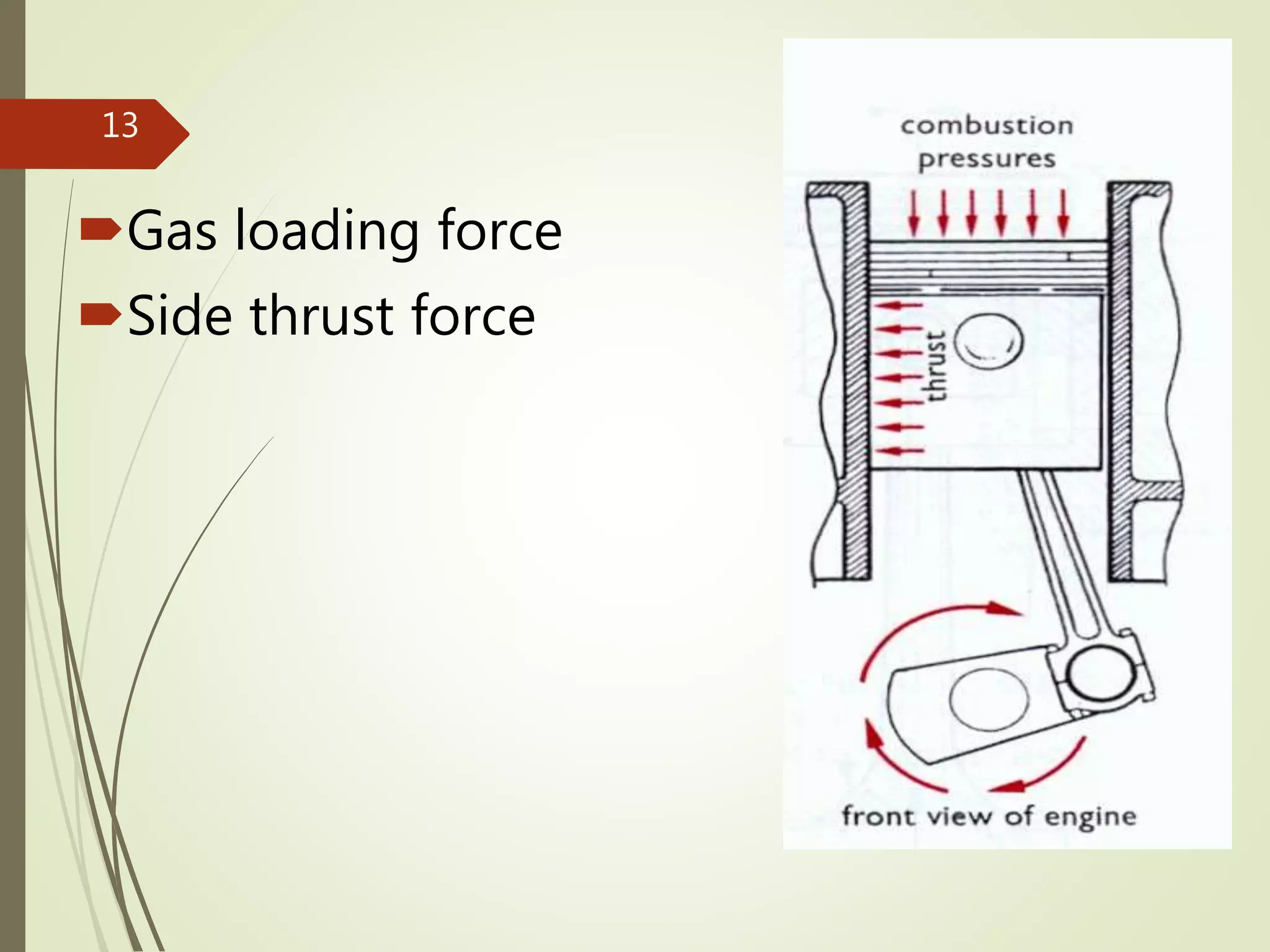
![FBD of piston
N =[ F*cos(α)/cos(φ)]- m*a - m*g
F= P/ r* ω =P/(2πn/60)*r (N)
Sin (φ) = r*sin(θ)/b => φ=sin–1 (r*sin(θ)/b)
θ+ φ+ α = 90o
α = 90o – [θ+ sin –1(r*sin(θ)/b)]
m = piston + connecting rod
a = r*ω2*[cos(θ)+cos(2* θ)/(2*b/r)]
N= [F*cos{90o–[θ+ sin –1(r*sin(θ)/b)]}*
cos{ sin–1 (r*sin(θ)/b)}]-m*a-m*g
14](https://image.slidesharecdn.com/ch02-180106185255/75/Internal-Combustion-Engine-Fundamental-Concepts-14-2048.jpg)
![ F(thrust) = F*cos(α)*sin(φ)
F(thrust)= F*cos{90o – [θ+ sin –1(r*sin(θ)/b)]}* r*sin(θ)/b
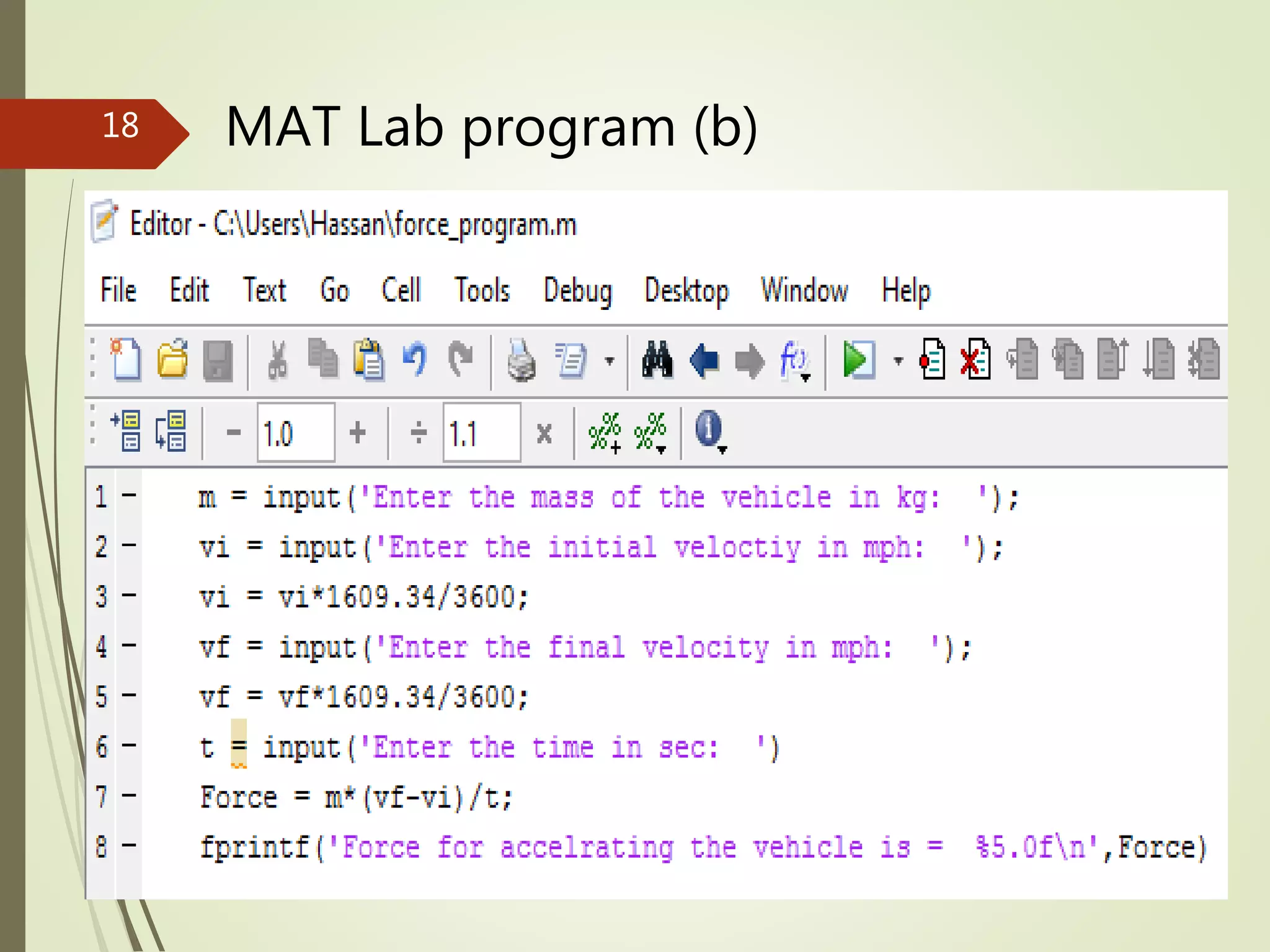
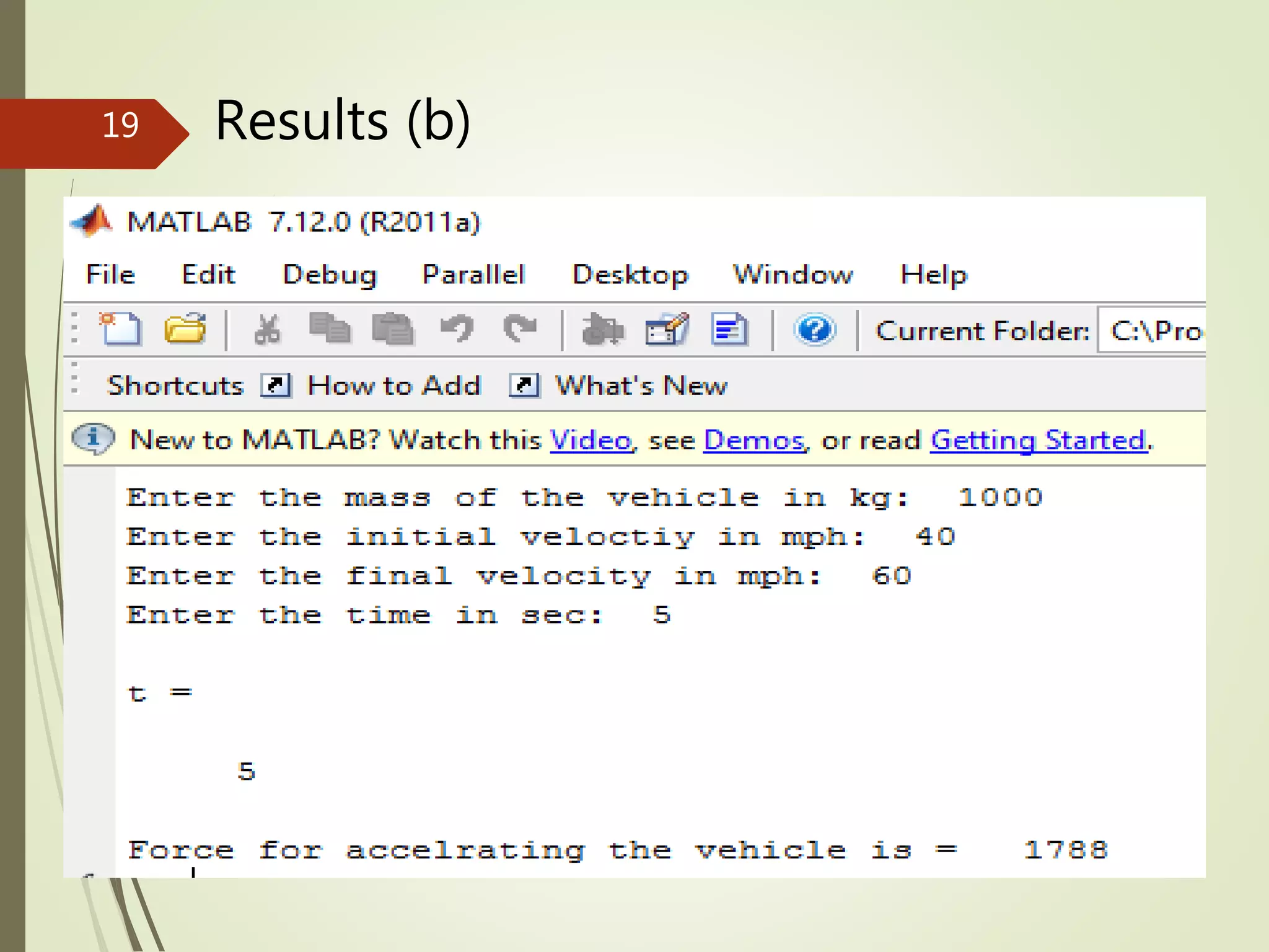
Force for accelrating the piston
F=m*a=m*(vf-vi)/t
15](https://image.slidesharecdn.com/ch02-180106185255/75/Internal-Combustion-Engine-Fundamental-Concepts-15-2048.jpg)


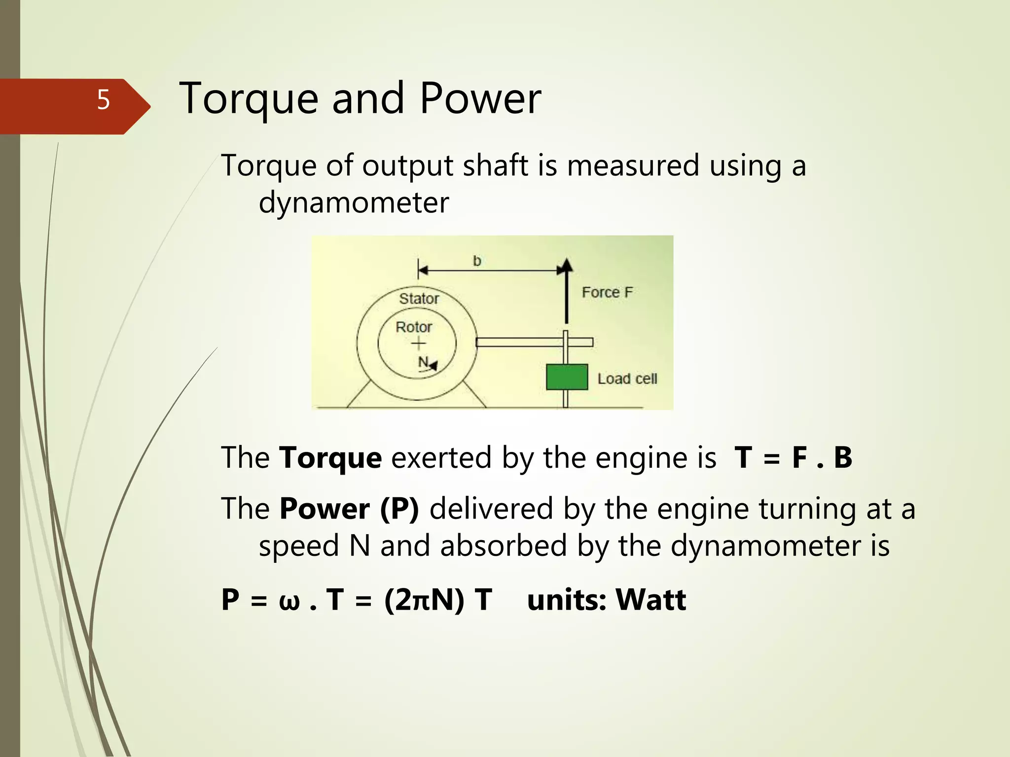
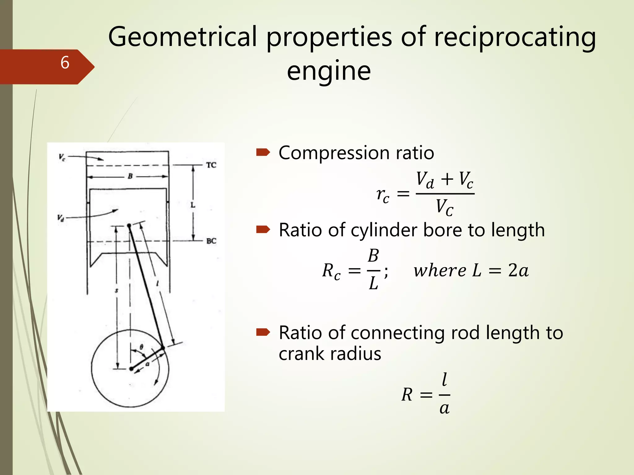
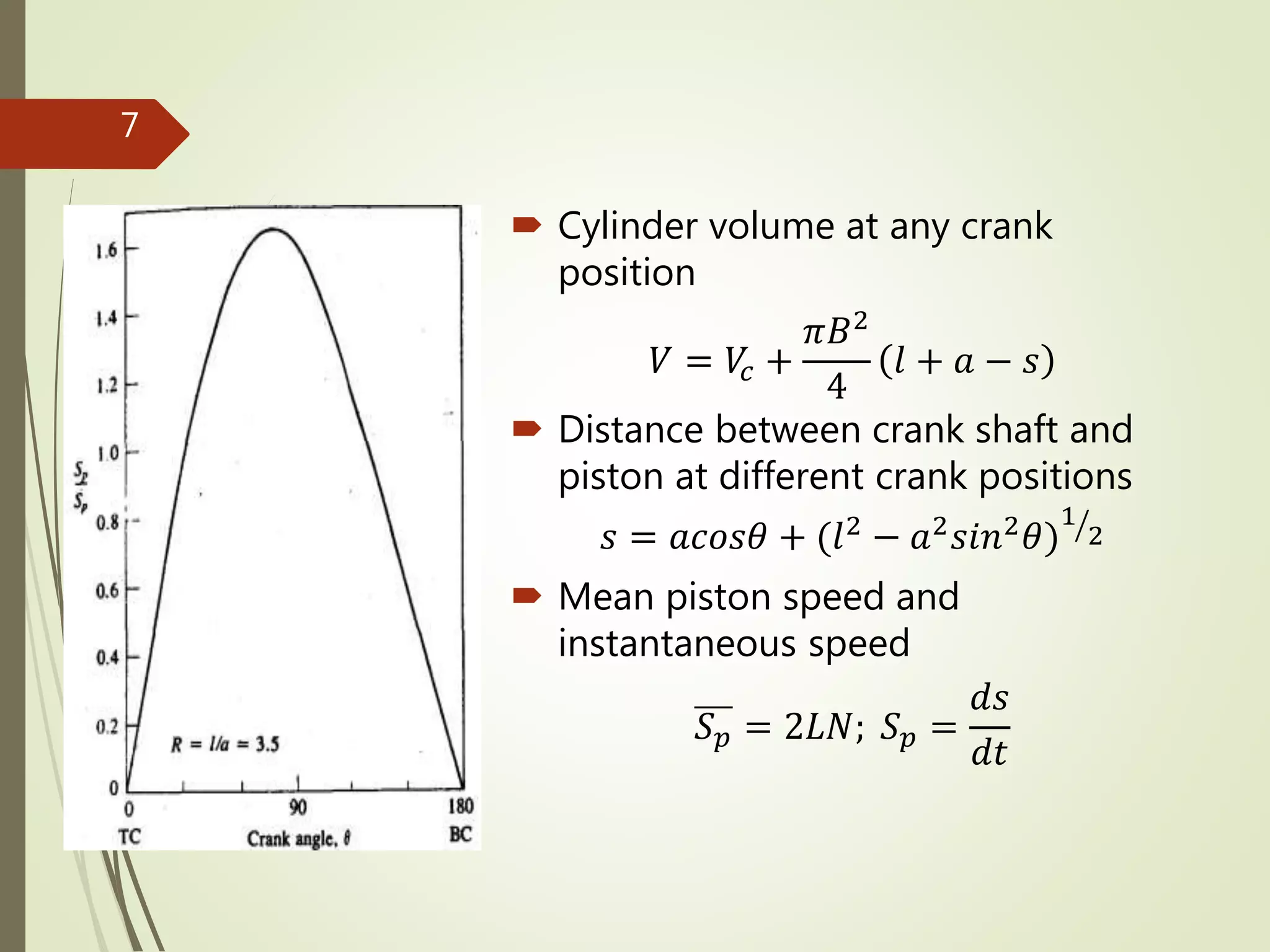
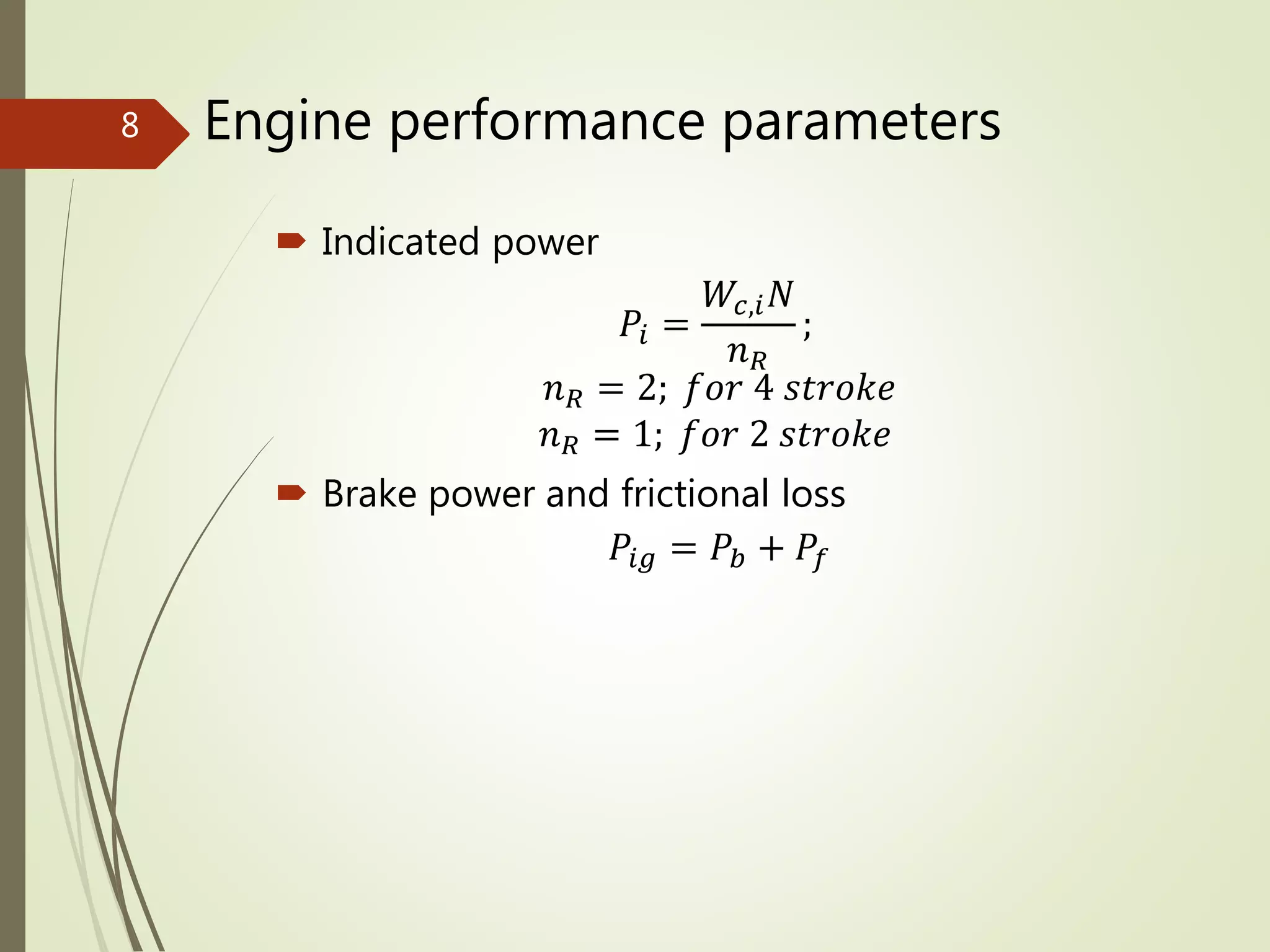
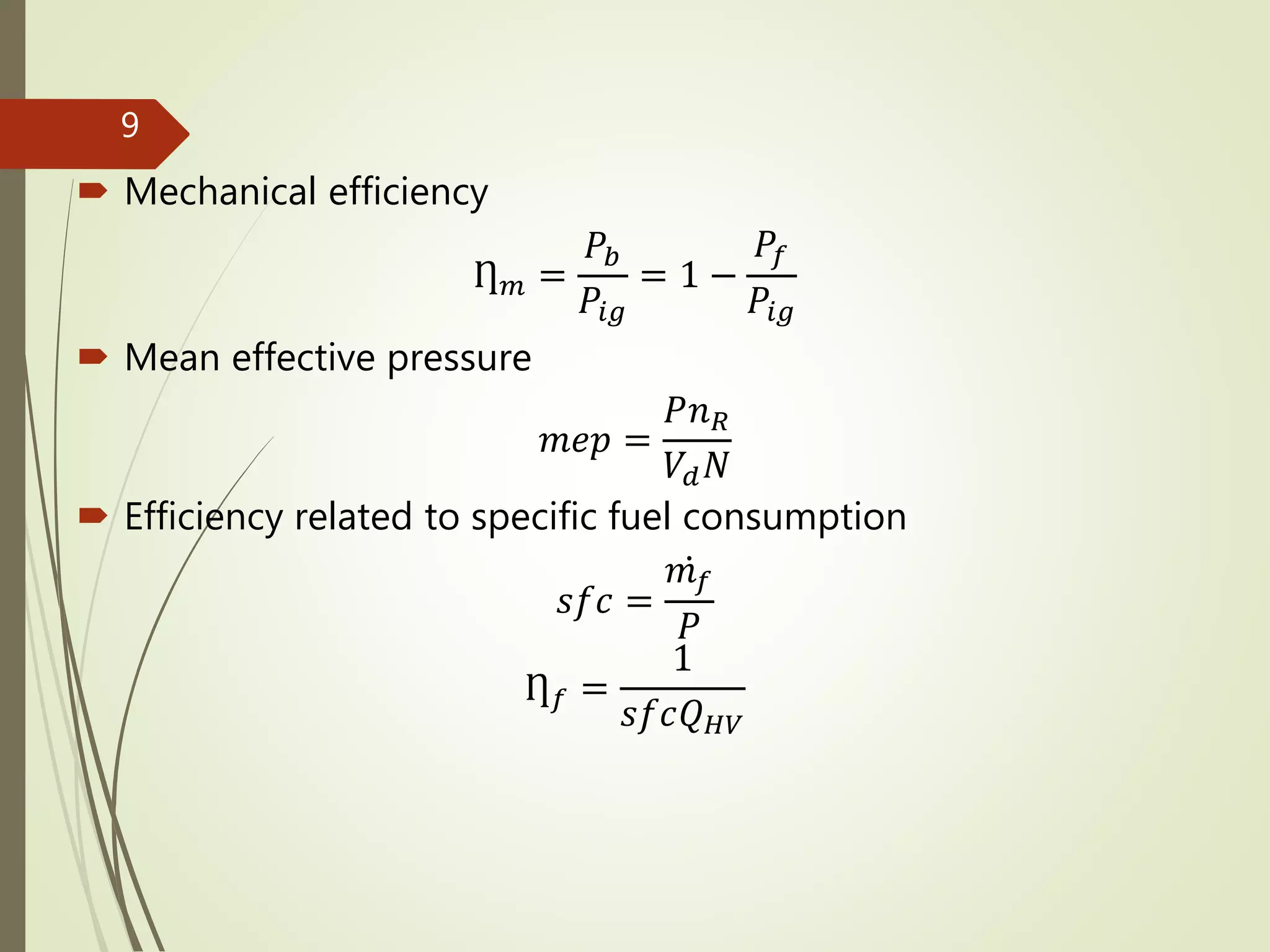
This document discusses the fundamentals of internal combustion engine design and operating parameters, covering performance definitions, torque and power measurements, and geometrical properties of reciprocating engines. It also presents various engine performance parameters, design comparisons between spark ignition and compression ignition engines, and related calculations such as gas loading force and side thrust force. The content is aimed at engineering students and includes MATLAB program references for problem-solving.