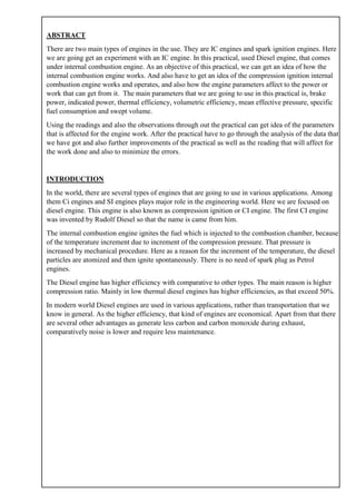
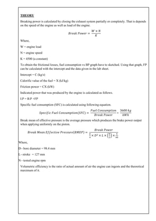
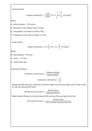
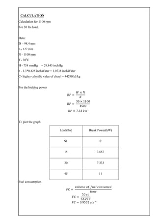
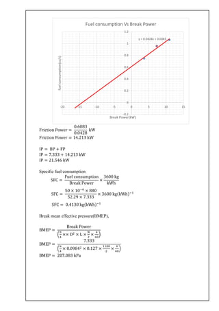
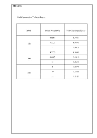
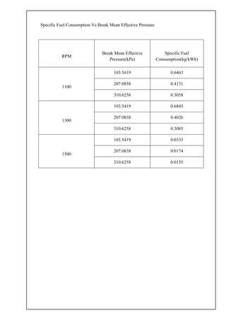
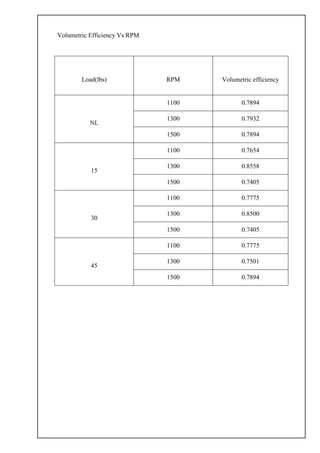
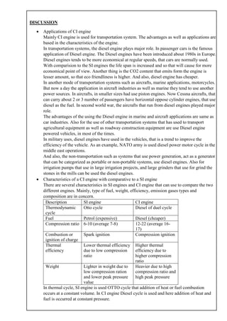
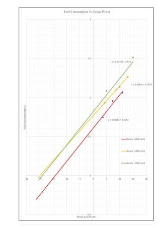
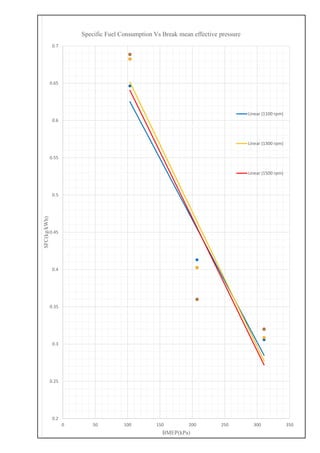
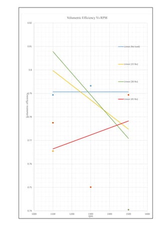
LOAD TEST ON A PERKINS DIESEL
ENGINE
EXPERIMENT NO.:
INSTRUCTED BY:
GROUP MEMBERS:
NAME :
COURSE : B.Sc. Engineering
INDEX NO. : 150131A
GROUP :
DATE OF PER. :
DATE OF SUB. :
ABSTRACT
There are two main types of engines in the use. They are IC engines and spark ignition engines. Here
we are going get an experiment with an IC engine. In this practical, used Diesel engine, that comes
under internal combustion engine. As an objective of this practical, we can get an idea of how the
internal combustion engine works. And also have to get an idea of the compression ignition internal
combustion engine works and operates, and also how the engine parameters affect to the power or
work that can get from it. The main parameters that we are going to use in this practical is, brake
power, indicated power, thermal efficiency, volumetric efficiency, mean effective pressure, specific
fuel consumption and swept volume.
Using the readings and also the observations through out the practical can get idea of the parameters
that is affected for the engine work. After the practical have to go through the analysis of the data that
we have got and also further improvements of the practical as well as the reading that will affect for
the work done and also to minimize the errors.
INTRODUCTION
In the world, there are several types of engines that are going to use in various applications. Among
them Ci engines and SI engines plays major role in the engineering world. Here we are focused on
diesel engine. This engine is also known as compression ignition or CI engine. The first CI engine
was invented by Rudolf Diesel so that the name is came from him.
The internal combustion engine ignites the fuel which is injected to the combustion chamber, because
of the temperature increment due to increment of the compression pressure. That pressure is
increased by mechanical procedure. Here as a reason for the increment of the temperature, the diesel
particles are atomized and then ignite spontaneously. There is no need of spark plug as Petrol
engines.
The Diesel engine has higher efficiency with comparative to other types. The main reason is higher
compression ratio. Mainly in low thermal diesel engines has higher efficiencies, as that exceed 50%.
In modern world Diesel engines are used in various applications, rather than transportation that we
know in general. As the higher efficiency, that kind of engines are economical. Apart from that there
are several other advantages as generate less carbon and carbon monoxide during exhaust,
comparatively noise is lower and require less maintenance.
THEORY
Breaking power is calculated by closing the exhaust system partially or completely. That is depends
on the speed of the engine as well as load of the engine.
𝐵𝑟𝑒𝑎𝑘 𝑃𝑜𝑤𝑒𝑟 =
𝑊 × 𝑁
𝐾
Where,
W = engine load
N = engine speed
K = 4500 (a constant)
To obtain the frictional losses, fuel consumption vs BP graph have to sketched. Using that graph, FP
can be calculated with the intercept and the data given in the lab sheet.
Intercept = C (kg/s)
Calorific value of the fuel = X (kJ/kg)
Friction power = CX (kW)
Indicated power that was produced by the engine is calculated as follows.
I.P = B.P +FP
Specific fuel consumption (SFC) is calculated using following equation.
𝑆𝑝𝑒𝑐𝑖𝑓𝑖𝑐 𝐹𝑢𝑒𝑙 𝐶𝑜𝑛𝑠𝑢𝑚𝑝𝑡𝑖𝑜𝑛(𝑆𝐹𝐶) =
𝐹𝑢𝑒𝑙 𝐶𝑜𝑛𝑠𝑢𝑚𝑝𝑡𝑖𝑜𝑛
𝐵𝑟𝑒𝑎𝑘 𝑃𝑜𝑤𝑒𝑟
∗
3600 𝑘𝑔
𝑘𝑊ℎ
Break mean of effective pressure is the average pressure which produces the brake power output
when applying uniformly on the piston.
𝐵𝑟𝑒𝑎𝑘 𝑀𝑒𝑎𝑛 𝐸𝑓𝑓𝑒𝑐𝑡𝑖𝑣𝑒 𝑃𝑟𝑒𝑠𝑠𝑢𝑟𝑒(𝐵𝑀𝐸𝑃) =
𝐵𝑟𝑒𝑎𝑘 𝑃𝑜𝑤𝑒𝑟
𝜋
4
× 𝐷2 × 𝐿 × (
𝑁
2
) ×
4
60
Where,
D - bore diameter = 98.4 mm
L- stroke = 127 mm
N - tested engine rpm
Volumetric efficiency is the ratio of actual amount of air the engine can ingests and the theoretical
maximum of it.
Volume inhaled
𝑉𝑜𝑙𝑢𝑚𝑒 𝑖𝑛ℎ𝑎𝑙𝑒𝑑(𝑉𝑖) =
4.193
35.22
× 𝑑2
× √ℎ ×
𝑇
𝐻
𝑚3(min)−1
Where,
d - orifice diameter – 2.05 inches
h - Manometer water head in inches of water
H - atmospheric air pressure in inches of Hg
T- temperature at the orifice in intake air vessel
Swept volume
𝑆𝑤𝑒𝑝𝑡 𝑉𝑜𝑙𝑢𝑚𝑒(𝑉𝑠) = 4 ×
𝜋
4
× 𝐷2
× 𝐿 ×
𝑁
2
𝑚3(min)−1
Where,
D - bore diameter = 98.4 mm
L- stroke = 127 mm
N - tested engine rpm
Volumetric efficiency
𝑉𝑜𝑙𝑢𝑚𝑒𝑡𝑟𝑖𝑐 𝐸𝑓𝑓𝑖𝑐𝑖𝑒𝑛𝑐𝑦 =
𝑉𝑜𝑙𝑢𝑚𝑒 𝑖𝑛ℎ𝑎𝑙𝑒𝑑
𝑆𝑤𝑒𝑝𝑡 𝑣𝑜𝑙𝑢𝑚𝑒
𝑉𝑜𝑙𝑢𝑚𝑒𝑡𝑟𝑖𝑐 𝐸𝑓𝑓𝑖𝑐𝑖𝑒𝑛𝑐𝑦 =
𝑉𝑖
𝑉𝑠
Mechanical efficiency ratio is the ratio in between output work and total input work. In other words,
it is the ratio between BP and IP
𝑀𝑒𝑐ℎ𝑎𝑛𝑖𝑐𝑎𝑙 𝑒𝑓𝑓𝑖𝑐𝑖𝑒𝑛𝑐𝑦 =
𝐵𝑟𝑒𝑎𝑘 𝑃𝑜𝑤𝑒𝑟
𝐼𝑛𝑑𝑖𝑐𝑎𝑡𝑒𝑑 𝑃𝑜𝑤𝑒𝑟
Break thermal efficiency is the ratio between BP and rate of the heat input by the fuel.
𝑂𝑣𝑒𝑟𝑎𝑙𝑙 𝑒𝑓𝑓𝑖𝑐𝑖𝑒𝑛𝑐𝑦 =
𝐵𝑟𝑒𝑎𝑘 𝑃𝑜𝑤𝑒𝑟
𝑅𝑎𝑡𝑒 𝑜𝑓 ℎ𝑒𝑎𝑡 𝑖𝑛𝑝𝑢𝑡 𝑏𝑦 𝑡ℎ𝑒 𝑓𝑢𝑒𝑙
APPARATUS
• 4-cylinder 4 stroke naturally aspired 3.86-liter Perkins diesel engine.
• Fraud hydraulic dynamometer
• Thermometers
• Venture flow meter
• Intake air controlling vessel
• Stopwatch
• Manometer
PROCEDURE
Open the inlet valve fully and the outlet valve slightly
All valves in the piping between the source of water supply and the dynamometer inlet are fully open.
Fuel availability is checked, otherwise make sure that the valve is open and let the fuel fill into the
tank.
The engine was started.
The rpm is adjusted using accelerator.
Load is regulated by opening the sluice gate by means of the hard wheel and simultaneous opening
the engine throttle, until the desired load and speed obtained.
Water was sufficiently applied through the piping system to maintain the temperature of the engine.
The applying load is measured and balanced using hand-wheel that is placed on the top of the balance
frame to adjust the height of the balance arm. The pin point at the bottom of the adjustment has to be
in position in order to maintain readable load.
Fuel consumption was measured using stopwatch, the time that is taken to decrease between the two
points in the indicator.
Temperature values of the cooling water inlet temperature, outlet temperate, and also engine exhaust
temperature is measured using thermometers and thermocouples.
Manometer reading was read in the air intake vessel.
The procedure was repeated for other readings that relevant to the different rpm of the engine.
CALCULATION
Calculation for 1100 rpm
For 30 lbs load,
Data:
D - 98.4 mm
L- 127 mm
N - 1100 rpm
T- 300
C
H - 758 mmHg = 29.843 inchHg
h - 1.3*0.826 inchWater = 1.0738 inchWater
C- higher calorific value of diesel = 44290 kJ/kg
For the braking power
𝐵𝑃 =
𝑊 × 𝑁
𝐾
𝐵𝑃 =
30 × 1100
4500
𝐵𝑃 = 7.33 𝑘𝑊
To plot the graph
Load(lbs) Break Power(kW)
NL 0
15 3.667
30 7.333
45 11
Fuel consumption
𝐹𝐶 =
𝑣𝑜𝑙𝑢𝑚𝑒 𝑜𝑓 𝑓𝑢𝑒𝑙 𝑐𝑜𝑛𝑠𝑢𝑚𝑒𝑑
𝑡𝑖𝑚𝑒
𝐹𝐶 =
50 𝑐𝑐
52.29 𝑠
𝐹𝐶 = 0.9562 𝑐𝑐𝑠−1
Friction Power =
0.6083
0.0428
kW
Friction Power = 14.213 kW
IP = BP + FP
IP = 7.333 + 14.213 kW
IP = 21.546 kW
Specific fuel consumption
SFC =
Fuel consumption
Break Power
×
3600 kg
kWh
SFC =
50 × 10−6
× 880
52.29 × 7.333
× 3600 kg(kWh)−1
SFC = 0.4130 kg(kWh)−1
Break mean effective pressure(BMEP),
BMEP =
Break Power
(
π
4
×× D2 × L ×
N
2
×
4
60
)
BMEP =
7.333
(
π
4
× 0.09842 × 0.127 ×
1100
2
×
4
60
)
BMEP = 207.083 kPa
y = 0.0428x + 0.6083
-0.2
0
0.2
0.4
0.6
0.8
1
1.2
-20 -15 -10 -5 0 5 10 15
fuelconsumption(cc/s)
Break Power(kW)
Fuel consumption Vs Break Power
Volume inhaled,
Vi =
4.193
35.22
× d2
× √h ×
T
H
Vi =
4.193
35.22
× 2.052
× √1.0738 ×
(273 + 30)
29.843
Vi = 1.6519 m3(min)−1
Swept Volume,
Vs = 4 ×
π
4
× D2
× L ×
N
2
Vs = 2.1247 m3(min)−1
Volumetric efficiency,
ηv =
Vi
Vs
ηv =
1.6519
2.1247
ηv = 0.7775
Mechanical efficiency,
ηM =
B. P
I. P
ηM =
7.33
21.546
ηM = 0.3403
Rate of heat input by the fuel,
Q̇ = ṁ × C
Q̇ =
V × ρ
t
× C
Q̇ =
50 × 10−6
× 880
52.29
× 44290
Q̇ = 37.2683 kW
Overall efficiency,
ηM =
B. P
Q̇
ηM =
7.33
37.2683
ηM = 0.1968
RESULTS
Fuel Consumption Vs Break Power
RPM Break Power(kW) Fuel Consumption(cc/s)
1100
3.6667 0.7481
7.3333 0.9562
11 1.0618
1300
4.3333 0.9335
8.6667 1.1013
13 1.2658
1500
5 1.0870
10 1.1364
15 1.5152
Specific Fuel Consumption Vs Break Mean Effective Pressure
RPM
Break Mean Effective
Pressure(kPa)
Specific Fuel
Consumption(kg/kWh)
1100
103.5419 0.6463
207.0838 0.4131
310.6258 0.3058
1300
103.5419 0.6845
207.0838 0.4026
310.6258 0.3085
1500
103.5419 0.0333
207.0838 0.0174
310.6258 0.0155
Volumetric Efficiency Vs RPM
Load(lbs) RPM Volumetric efficiency
NL
1100 0.7894
1300 0.7932
1500 0.7894
15
1100 0.7654
1300 0.8558
1500 0.7405
30
1100 0.7775
1300 0.8500
1500 0.7405
45
1100 0.7775
1300 0.7501
1500 0.7894
DISCUSSION
• Applications of CI engine
Mainly CI engine is used for transportation system. The advantages as well as applications are
based in the characteristics of the engine.
In transportation systems, the diesel engine plays major role. In passenger cars is the famous
application of Diesel engine. The Diesel engines have been introduced about 1980s in Europe.
Diesel engines tends to be more economical at regular speeds, that cars are normally used.
With comparision to the SI engines the life span is increased and so that will cause for more
economical point of view. Another thing is the CO2 content that emits form the engine is
lesser amount, so that eco friendliness is higher. And also, diesel engine has cheaper.
In another mode of transportation systems such as aircrafts, marine applications, motorcycles.
But now a day the application in aircraft industries as well as marine they tend to use another
power sources. In aircrafts, in smaller sizes had use piston engines. Now Cessna aircrafts, that
can carry about 2 or 3 number of passengers have horizontal oppose cylinder engines, that use
diesel as the fuel. In second world war, the aircrafts that run from diesel engines played major
role.
The advantages of the using the Diesel engine in marine and aircraft applications are same as
car industries. Also for the use of other transportation systems that has used to transport
agricultural equipment as well as roadway construction equipment are use Diesel engine
powered vehicles, in most of the times.
In military uses, diesel engines have used in the vehicles, that is a trend to improve the
efficiency of the vehicle. As an example, NATO army is used diesel power motor cycle in the
middle east operations.
And also, the non-transportation such as systems that use power generation, act as a generator
that can be categorized as portable or non-portable systems, use diesel engines. Also for
irrigation pumps that use in large irrigation projects, and large grinders that use for grind the
stones in the mills can be used the diesel engines.
• Characteristics of a CI engine with comparative to a SI engine
There are several characteristics in SI engines and CI engine that can use to compare the two
different engines. Mainly, type of fuel, weight, efficiency, emission gases types and
composition are in concern.
Description SI engine CI engine
Thermodynamic
cycle
Otto cycle Diesel of duel cycle
Fuel Petrol (expensive) Diesel (cheaper)
Compression ratio 6-10 (average 7-8) 12-22 (average 16-
17)
Combustion or
ignition of charge
Spark ignition Compression ignition
Thermal
efficiency
Lower thermal efficiency
due to low compression
ratio
Higher thermal
efficiency due to
higher compression
ratio
Weight Lighter in weight due to
low compression ration
and lower peak pressure
value
Heavier due to high
compression ratio and
high peak pressure
In thermal cycle, SI engine is used OTTO cycle that addition of heat or fuel combustion
occurs at a constant volume. In CI engine Diesel cycle is used and here addition of heat and
fuel is occurred at constant pressure.
In SI engine, mix of fuel and air is introduced in to the piston via carburetor that control the
quantity as well as quality of the air fuel mixture. In CI engine fuel is added to the combustion
chamber towards the end of the compression stroke. Here use fuel pump and injector.
• Dynamometer and types of engine dynamometer
That is a device that is to measure torque and brake power required to operate a driven
machine. Mainly there are two types of dynamometers, power absorption dynamometer and
power transmission dynamometer.
Power absorption dynamometer measure and absorb the power output that is coupled. Power
absorption is usually dissipated as heat. There are several power absorption dynamometers
such as Prony break dynamometer, Rope brake dynamometer, Eddy current dynamometer,
Hydraulic dynamometer etc.
In power transmission dynamometer that transmitted the load couple to the engine after it is
indicated on some scale. Also known as torque meters.
In Prony break dynamometer, it is the simplest dynamometer, that attempts to stop the engine
using brake on the flywheel. The Rope brake dynamometer consists of some turns of rope
rotating around a drum. The power is absorbed in friction of the rope and drum.
In eddy current dynamometer there are several advantages like that is high brake power per
unit weight of dynamometer. That is offered highest ratio of constant power speed range. It
has higher torque under low speed condition.
in hydraulic dynamometer, the construction is similar to that of a fluid flywheel. That is
consists of an impeller or inner rotating member coupled to the output shaft of the engine. The
friction forces generated between the impeller and the fluid is measured using spring balance
fitted on the casting.
The absorption dynamometers are called as torque meters. They are mostly consisting of a set
of strain gauges, that is fixed on the rotating disk. The angular deformation of the strain
gauges is measured of the shaft.
• Components of heat balance equation of a CI engine
The equation for the heat balance of the CI engine is defined as
𝐻𝑒𝑎𝑡 𝑔𝑒𝑛𝑒𝑟𝑎𝑡𝑒𝑑 𝑖𝑛 𝑐𝑜𝑚𝑏𝑢𝑠𝑡𝑖𝑜𝑛 𝑜𝑓 𝑡ℎ𝑒 𝑓𝑢𝑒𝑙
+ 𝑚𝑒𝑐ℎ𝑎𝑛𝑖𝑐𝑎𝑙 𝑝𝑜𝑤𝑒𝑟 𝑖𝑛𝑝𝑢𝑡 𝑓𝑜𝑟 𝑐𝑜𝑚𝑝𝑟𝑒𝑠𝑠𝑖𝑜𝑛
= 𝑚𝑒𝑐ℎ𝑎𝑛𝑖𝑐𝑎𝑙 𝑒𝑛𝑒𝑟𝑔𝑦 𝑜𝑢𝑡𝑝𝑢𝑡 + 𝑒𝑛𝑒𝑟𝑔𝑦 𝑙𝑜𝑠𝑠𝑒𝑠
The energy losses can be categorized under three categories as follows.
o Heat loss to coolant
o Heat loss to exhaust
o Frictional losses
So that the total energy losses are described as
𝑒𝑛𝑒𝑟𝑔𝑦 𝑙𝑜𝑠𝑠 = ℎ𝑒𝑎𝑡 𝑙𝑜𝑠𝑠 𝑡𝑜 𝑐𝑜𝑜𝑙𝑒𝑛𝑡 + ℎ𝑒𝑎𝑡 𝑙𝑜𝑠𝑠 𝑡𝑜 𝑒𝑥ℎ𝑎𝑢𝑠𝑡 + 𝑓𝑟𝑖𝑐𝑡𝑖𝑜𝑛 𝑙𝑜𝑠𝑠
In the coolants, the energy is loss in order to increase the temperature of the coolants. So
that the coolants are carried out energy that generated.
In heat loss in exhaust, because exhausting gas carried some part of the energy that is
generated during the thermodynamic cycle. That cannot be recoverable. In engines that
cannot be used as air preheater, specially in locomotives so that, that energy is wasted.
The frictional losses are undesirable. We cannot avoid that but using coolants as well as
well maintaining the engine via services, can reduce frictional losses.
• Importance of calculating the above performance indices of the engine
Basically, mechanical efficiency provides and indicates how much mechanical work that
gives by the engine with respect to the energy that we have supplied. By using that values we
can say that how the engine is worked and is the engine works during profitable region. We
can compare general values with the values that get from the engine and decide what are the
improvements to take to increase the efficiency.
In specific fuel consumption values, indicated how much fuel use in order to get the work. If
the fuel consumption is higher, sometimes the work will have reduced. So that we can get an
idea of the fuel consumption with the amount of work. If the work is low with respect to the
work done, we have to take some actions to reduce the specific fuel consumption and get the
higher work. That is an indictor of the energy losses due to less maintenance.
The volumetric efficiency gives us how much air get filled into the cylinder during stroke.
That will help us to get an idea about the combustion in low oxygen condition or higher
oxygen condition. So, have to consider about the best air to fuel ration in order to increase the
efficiency of the engine.
In overall efficiency of the that is the indicator of the mechanical work output respect to the
chemical energy input to the engine. By changing the parameters of the engine have to get the
optimum efficiency from the engine.
• Error minimization of the experiment
o Readings must take after some times that will take for the engine to settle under some
set of constant variables.
o Maintain the load applied on the engine constant, and get corrected load values.
o Use horizontal indicator to read the manometer readings in the air tank
o Maintain the constant rpm during the process, have to correct acceleration as fast as
we can if there any changes.
o Can minimize the time measuring errors, by taking time for 100cc values rather than
50cc values.
References
Swagatam, H. K. (2008, 5 11). Comparison of Spark Ignition (SI) and Compression Ignition (CI) engines.
Retrieved from Bright hub engineering: http://www.brighthubengineering.com/machine-design/1537-
comparison-of-spark-ignition-si-and-compression-ignition-ci-engines/
y = 0.0428x + 0.6083
y = 0.0383x + 0.7679
y = 0.0428x + 0.818
-0.5
0
0.5
1
1.5
2
-25 -20 -15 -10 -5 0 5 10 15 20
fuelconsumption(cc/s)
Break power(kW)
Fuel Consumption Vs Break Power
Linear (1100 rpm)
Linear (1300 rpm)
Linear (1500 rpm)
0.2
0.25
0.3
0.35
0.4
0.45
0.5
0.55
0.6
0.65
0.7
0 50 100 150 200 250 300 350
SFC(kg/kWh)
BMEP(kPa)
Specific Fuel Consumption Vs Break mean effective pressure
Linear (1100 rpm)
Linear (1300 rpm)
Linear (1500 rpm)
0.74
0.75
0.76
0.77
0.78
0.79
0.8
0.81
0.82
1000 1100 1200 1300 1400 1500 1600
Volumetricefficiency
rpm
Volumetric Efficiency Vs RPM
Linear (No load)
Linear (15 lbs)
Linear (30 lbs)
Linear (45 lbs)
Load test on a perkins diesel engine

Load test on a perkins diesel engine

  • 1.
    LOAD TEST ONA PERKINS DIESEL ENGINE EXPERIMENT NO.: INSTRUCTED BY: GROUP MEMBERS: NAME : COURSE : B.Sc. Engineering INDEX NO. : 150131A GROUP : DATE OF PER. : DATE OF SUB. :
  • 2.
    ABSTRACT There are twomain types of engines in the use. They are IC engines and spark ignition engines. Here we are going get an experiment with an IC engine. In this practical, used Diesel engine, that comes under internal combustion engine. As an objective of this practical, we can get an idea of how the internal combustion engine works. And also have to get an idea of the compression ignition internal combustion engine works and operates, and also how the engine parameters affect to the power or work that can get from it. The main parameters that we are going to use in this practical is, brake power, indicated power, thermal efficiency, volumetric efficiency, mean effective pressure, specific fuel consumption and swept volume. Using the readings and also the observations through out the practical can get idea of the parameters that is affected for the engine work. After the practical have to go through the analysis of the data that we have got and also further improvements of the practical as well as the reading that will affect for the work done and also to minimize the errors. INTRODUCTION In the world, there are several types of engines that are going to use in various applications. Among them Ci engines and SI engines plays major role in the engineering world. Here we are focused on diesel engine. This engine is also known as compression ignition or CI engine. The first CI engine was invented by Rudolf Diesel so that the name is came from him. The internal combustion engine ignites the fuel which is injected to the combustion chamber, because of the temperature increment due to increment of the compression pressure. That pressure is increased by mechanical procedure. Here as a reason for the increment of the temperature, the diesel particles are atomized and then ignite spontaneously. There is no need of spark plug as Petrol engines. The Diesel engine has higher efficiency with comparative to other types. The main reason is higher compression ratio. Mainly in low thermal diesel engines has higher efficiencies, as that exceed 50%. In modern world Diesel engines are used in various applications, rather than transportation that we know in general. As the higher efficiency, that kind of engines are economical. Apart from that there are several other advantages as generate less carbon and carbon monoxide during exhaust, comparatively noise is lower and require less maintenance.
  • 3.
    THEORY Breaking power iscalculated by closing the exhaust system partially or completely. That is depends on the speed of the engine as well as load of the engine. 𝐵𝑟𝑒𝑎𝑘 𝑃𝑜𝑤𝑒𝑟 = 𝑊 × 𝑁 𝐾 Where, W = engine load N = engine speed K = 4500 (a constant) To obtain the frictional losses, fuel consumption vs BP graph have to sketched. Using that graph, FP can be calculated with the intercept and the data given in the lab sheet. Intercept = C (kg/s) Calorific value of the fuel = X (kJ/kg) Friction power = CX (kW) Indicated power that was produced by the engine is calculated as follows. I.P = B.P +FP Specific fuel consumption (SFC) is calculated using following equation. 𝑆𝑝𝑒𝑐𝑖𝑓𝑖𝑐 𝐹𝑢𝑒𝑙 𝐶𝑜𝑛𝑠𝑢𝑚𝑝𝑡𝑖𝑜𝑛(𝑆𝐹𝐶) = 𝐹𝑢𝑒𝑙 𝐶𝑜𝑛𝑠𝑢𝑚𝑝𝑡𝑖𝑜𝑛 𝐵𝑟𝑒𝑎𝑘 𝑃𝑜𝑤𝑒𝑟 ∗ 3600 𝑘𝑔 𝑘𝑊ℎ Break mean of effective pressure is the average pressure which produces the brake power output when applying uniformly on the piston. 𝐵𝑟𝑒𝑎𝑘 𝑀𝑒𝑎𝑛 𝐸𝑓𝑓𝑒𝑐𝑡𝑖𝑣𝑒 𝑃𝑟𝑒𝑠𝑠𝑢𝑟𝑒(𝐵𝑀𝐸𝑃) = 𝐵𝑟𝑒𝑎𝑘 𝑃𝑜𝑤𝑒𝑟 𝜋 4 × 𝐷2 × 𝐿 × ( 𝑁 2 ) × 4 60 Where, D - bore diameter = 98.4 mm L- stroke = 127 mm N - tested engine rpm Volumetric efficiency is the ratio of actual amount of air the engine can ingests and the theoretical maximum of it.
  • 4.
    Volume inhaled 𝑉𝑜𝑙𝑢𝑚𝑒 𝑖𝑛ℎ𝑎𝑙𝑒𝑑(𝑉𝑖)= 4.193 35.22 × 𝑑2 × √ℎ × 𝑇 𝐻 𝑚3(min)−1 Where, d - orifice diameter – 2.05 inches h - Manometer water head in inches of water H - atmospheric air pressure in inches of Hg T- temperature at the orifice in intake air vessel Swept volume 𝑆𝑤𝑒𝑝𝑡 𝑉𝑜𝑙𝑢𝑚𝑒(𝑉𝑠) = 4 × 𝜋 4 × 𝐷2 × 𝐿 × 𝑁 2 𝑚3(min)−1 Where, D - bore diameter = 98.4 mm L- stroke = 127 mm N - tested engine rpm Volumetric efficiency 𝑉𝑜𝑙𝑢𝑚𝑒𝑡𝑟𝑖𝑐 𝐸𝑓𝑓𝑖𝑐𝑖𝑒𝑛𝑐𝑦 = 𝑉𝑜𝑙𝑢𝑚𝑒 𝑖𝑛ℎ𝑎𝑙𝑒𝑑 𝑆𝑤𝑒𝑝𝑡 𝑣𝑜𝑙𝑢𝑚𝑒 𝑉𝑜𝑙𝑢𝑚𝑒𝑡𝑟𝑖𝑐 𝐸𝑓𝑓𝑖𝑐𝑖𝑒𝑛𝑐𝑦 = 𝑉𝑖 𝑉𝑠 Mechanical efficiency ratio is the ratio in between output work and total input work. In other words, it is the ratio between BP and IP 𝑀𝑒𝑐ℎ𝑎𝑛𝑖𝑐𝑎𝑙 𝑒𝑓𝑓𝑖𝑐𝑖𝑒𝑛𝑐𝑦 = 𝐵𝑟𝑒𝑎𝑘 𝑃𝑜𝑤𝑒𝑟 𝐼𝑛𝑑𝑖𝑐𝑎𝑡𝑒𝑑 𝑃𝑜𝑤𝑒𝑟 Break thermal efficiency is the ratio between BP and rate of the heat input by the fuel. 𝑂𝑣𝑒𝑟𝑎𝑙𝑙 𝑒𝑓𝑓𝑖𝑐𝑖𝑒𝑛𝑐𝑦 = 𝐵𝑟𝑒𝑎𝑘 𝑃𝑜𝑤𝑒𝑟 𝑅𝑎𝑡𝑒 𝑜𝑓 ℎ𝑒𝑎𝑡 𝑖𝑛𝑝𝑢𝑡 𝑏𝑦 𝑡ℎ𝑒 𝑓𝑢𝑒𝑙
  • 5.
    APPARATUS • 4-cylinder 4stroke naturally aspired 3.86-liter Perkins diesel engine. • Fraud hydraulic dynamometer • Thermometers • Venture flow meter • Intake air controlling vessel • Stopwatch • Manometer PROCEDURE Open the inlet valve fully and the outlet valve slightly All valves in the piping between the source of water supply and the dynamometer inlet are fully open. Fuel availability is checked, otherwise make sure that the valve is open and let the fuel fill into the tank. The engine was started. The rpm is adjusted using accelerator. Load is regulated by opening the sluice gate by means of the hard wheel and simultaneous opening the engine throttle, until the desired load and speed obtained. Water was sufficiently applied through the piping system to maintain the temperature of the engine. The applying load is measured and balanced using hand-wheel that is placed on the top of the balance frame to adjust the height of the balance arm. The pin point at the bottom of the adjustment has to be in position in order to maintain readable load. Fuel consumption was measured using stopwatch, the time that is taken to decrease between the two points in the indicator. Temperature values of the cooling water inlet temperature, outlet temperate, and also engine exhaust temperature is measured using thermometers and thermocouples. Manometer reading was read in the air intake vessel. The procedure was repeated for other readings that relevant to the different rpm of the engine.
  • 6.
    CALCULATION Calculation for 1100rpm For 30 lbs load, Data: D - 98.4 mm L- 127 mm N - 1100 rpm T- 300 C H - 758 mmHg = 29.843 inchHg h - 1.3*0.826 inchWater = 1.0738 inchWater C- higher calorific value of diesel = 44290 kJ/kg For the braking power 𝐵𝑃 = 𝑊 × 𝑁 𝐾 𝐵𝑃 = 30 × 1100 4500 𝐵𝑃 = 7.33 𝑘𝑊 To plot the graph Load(lbs) Break Power(kW) NL 0 15 3.667 30 7.333 45 11 Fuel consumption 𝐹𝐶 = 𝑣𝑜𝑙𝑢𝑚𝑒 𝑜𝑓 𝑓𝑢𝑒𝑙 𝑐𝑜𝑛𝑠𝑢𝑚𝑒𝑑 𝑡𝑖𝑚𝑒 𝐹𝐶 = 50 𝑐𝑐 52.29 𝑠 𝐹𝐶 = 0.9562 𝑐𝑐𝑠−1
  • 7.
    Friction Power = 0.6083 0.0428 kW FrictionPower = 14.213 kW IP = BP + FP IP = 7.333 + 14.213 kW IP = 21.546 kW Specific fuel consumption SFC = Fuel consumption Break Power × 3600 kg kWh SFC = 50 × 10−6 × 880 52.29 × 7.333 × 3600 kg(kWh)−1 SFC = 0.4130 kg(kWh)−1 Break mean effective pressure(BMEP), BMEP = Break Power ( π 4 ×× D2 × L × N 2 × 4 60 ) BMEP = 7.333 ( π 4 × 0.09842 × 0.127 × 1100 2 × 4 60 ) BMEP = 207.083 kPa y = 0.0428x + 0.6083 -0.2 0 0.2 0.4 0.6 0.8 1 1.2 -20 -15 -10 -5 0 5 10 15 fuelconsumption(cc/s) Break Power(kW) Fuel consumption Vs Break Power
  • 8.
    Volume inhaled, Vi = 4.193 35.22 ×d2 × √h × T H Vi = 4.193 35.22 × 2.052 × √1.0738 × (273 + 30) 29.843 Vi = 1.6519 m3(min)−1 Swept Volume, Vs = 4 × π 4 × D2 × L × N 2 Vs = 2.1247 m3(min)−1 Volumetric efficiency, ηv = Vi Vs ηv = 1.6519 2.1247 ηv = 0.7775 Mechanical efficiency, ηM = B. P I. P ηM = 7.33 21.546 ηM = 0.3403 Rate of heat input by the fuel, Q̇ = ṁ × C Q̇ = V × ρ t × C Q̇ = 50 × 10−6 × 880 52.29 × 44290 Q̇ = 37.2683 kW Overall efficiency, ηM = B. P Q̇ ηM = 7.33 37.2683 ηM = 0.1968
  • 9.
    RESULTS Fuel Consumption VsBreak Power RPM Break Power(kW) Fuel Consumption(cc/s) 1100 3.6667 0.7481 7.3333 0.9562 11 1.0618 1300 4.3333 0.9335 8.6667 1.1013 13 1.2658 1500 5 1.0870 10 1.1364 15 1.5152
  • 10.
    Specific Fuel ConsumptionVs Break Mean Effective Pressure RPM Break Mean Effective Pressure(kPa) Specific Fuel Consumption(kg/kWh) 1100 103.5419 0.6463 207.0838 0.4131 310.6258 0.3058 1300 103.5419 0.6845 207.0838 0.4026 310.6258 0.3085 1500 103.5419 0.0333 207.0838 0.0174 310.6258 0.0155
  • 11.
    Volumetric Efficiency VsRPM Load(lbs) RPM Volumetric efficiency NL 1100 0.7894 1300 0.7932 1500 0.7894 15 1100 0.7654 1300 0.8558 1500 0.7405 30 1100 0.7775 1300 0.8500 1500 0.7405 45 1100 0.7775 1300 0.7501 1500 0.7894
  • 12.
    DISCUSSION • Applications ofCI engine Mainly CI engine is used for transportation system. The advantages as well as applications are based in the characteristics of the engine. In transportation systems, the diesel engine plays major role. In passenger cars is the famous application of Diesel engine. The Diesel engines have been introduced about 1980s in Europe. Diesel engines tends to be more economical at regular speeds, that cars are normally used. With comparision to the SI engines the life span is increased and so that will cause for more economical point of view. Another thing is the CO2 content that emits form the engine is lesser amount, so that eco friendliness is higher. And also, diesel engine has cheaper. In another mode of transportation systems such as aircrafts, marine applications, motorcycles. But now a day the application in aircraft industries as well as marine they tend to use another power sources. In aircrafts, in smaller sizes had use piston engines. Now Cessna aircrafts, that can carry about 2 or 3 number of passengers have horizontal oppose cylinder engines, that use diesel as the fuel. In second world war, the aircrafts that run from diesel engines played major role. The advantages of the using the Diesel engine in marine and aircraft applications are same as car industries. Also for the use of other transportation systems that has used to transport agricultural equipment as well as roadway construction equipment are use Diesel engine powered vehicles, in most of the times. In military uses, diesel engines have used in the vehicles, that is a trend to improve the efficiency of the vehicle. As an example, NATO army is used diesel power motor cycle in the middle east operations. And also, the non-transportation such as systems that use power generation, act as a generator that can be categorized as portable or non-portable systems, use diesel engines. Also for irrigation pumps that use in large irrigation projects, and large grinders that use for grind the stones in the mills can be used the diesel engines. • Characteristics of a CI engine with comparative to a SI engine There are several characteristics in SI engines and CI engine that can use to compare the two different engines. Mainly, type of fuel, weight, efficiency, emission gases types and composition are in concern. Description SI engine CI engine Thermodynamic cycle Otto cycle Diesel of duel cycle Fuel Petrol (expensive) Diesel (cheaper) Compression ratio 6-10 (average 7-8) 12-22 (average 16- 17) Combustion or ignition of charge Spark ignition Compression ignition Thermal efficiency Lower thermal efficiency due to low compression ratio Higher thermal efficiency due to higher compression ratio Weight Lighter in weight due to low compression ration and lower peak pressure value Heavier due to high compression ratio and high peak pressure In thermal cycle, SI engine is used OTTO cycle that addition of heat or fuel combustion occurs at a constant volume. In CI engine Diesel cycle is used and here addition of heat and fuel is occurred at constant pressure.
  • 13.
    In SI engine,mix of fuel and air is introduced in to the piston via carburetor that control the quantity as well as quality of the air fuel mixture. In CI engine fuel is added to the combustion chamber towards the end of the compression stroke. Here use fuel pump and injector. • Dynamometer and types of engine dynamometer That is a device that is to measure torque and brake power required to operate a driven machine. Mainly there are two types of dynamometers, power absorption dynamometer and power transmission dynamometer. Power absorption dynamometer measure and absorb the power output that is coupled. Power absorption is usually dissipated as heat. There are several power absorption dynamometers such as Prony break dynamometer, Rope brake dynamometer, Eddy current dynamometer, Hydraulic dynamometer etc. In power transmission dynamometer that transmitted the load couple to the engine after it is indicated on some scale. Also known as torque meters. In Prony break dynamometer, it is the simplest dynamometer, that attempts to stop the engine using brake on the flywheel. The Rope brake dynamometer consists of some turns of rope rotating around a drum. The power is absorbed in friction of the rope and drum. In eddy current dynamometer there are several advantages like that is high brake power per unit weight of dynamometer. That is offered highest ratio of constant power speed range. It has higher torque under low speed condition. in hydraulic dynamometer, the construction is similar to that of a fluid flywheel. That is consists of an impeller or inner rotating member coupled to the output shaft of the engine. The friction forces generated between the impeller and the fluid is measured using spring balance fitted on the casting. The absorption dynamometers are called as torque meters. They are mostly consisting of a set of strain gauges, that is fixed on the rotating disk. The angular deformation of the strain gauges is measured of the shaft. • Components of heat balance equation of a CI engine The equation for the heat balance of the CI engine is defined as 𝐻𝑒𝑎𝑡 𝑔𝑒𝑛𝑒𝑟𝑎𝑡𝑒𝑑 𝑖𝑛 𝑐𝑜𝑚𝑏𝑢𝑠𝑡𝑖𝑜𝑛 𝑜𝑓 𝑡ℎ𝑒 𝑓𝑢𝑒𝑙 + 𝑚𝑒𝑐ℎ𝑎𝑛𝑖𝑐𝑎𝑙 𝑝𝑜𝑤𝑒𝑟 𝑖𝑛𝑝𝑢𝑡 𝑓𝑜𝑟 𝑐𝑜𝑚𝑝𝑟𝑒𝑠𝑠𝑖𝑜𝑛 = 𝑚𝑒𝑐ℎ𝑎𝑛𝑖𝑐𝑎𝑙 𝑒𝑛𝑒𝑟𝑔𝑦 𝑜𝑢𝑡𝑝𝑢𝑡 + 𝑒𝑛𝑒𝑟𝑔𝑦 𝑙𝑜𝑠𝑠𝑒𝑠 The energy losses can be categorized under three categories as follows. o Heat loss to coolant o Heat loss to exhaust o Frictional losses So that the total energy losses are described as 𝑒𝑛𝑒𝑟𝑔𝑦 𝑙𝑜𝑠𝑠 = ℎ𝑒𝑎𝑡 𝑙𝑜𝑠𝑠 𝑡𝑜 𝑐𝑜𝑜𝑙𝑒𝑛𝑡 + ℎ𝑒𝑎𝑡 𝑙𝑜𝑠𝑠 𝑡𝑜 𝑒𝑥ℎ𝑎𝑢𝑠𝑡 + 𝑓𝑟𝑖𝑐𝑡𝑖𝑜𝑛 𝑙𝑜𝑠𝑠 In the coolants, the energy is loss in order to increase the temperature of the coolants. So that the coolants are carried out energy that generated. In heat loss in exhaust, because exhausting gas carried some part of the energy that is generated during the thermodynamic cycle. That cannot be recoverable. In engines that cannot be used as air preheater, specially in locomotives so that, that energy is wasted. The frictional losses are undesirable. We cannot avoid that but using coolants as well as well maintaining the engine via services, can reduce frictional losses. • Importance of calculating the above performance indices of the engine Basically, mechanical efficiency provides and indicates how much mechanical work that gives by the engine with respect to the energy that we have supplied. By using that values we
  • 14.
    can say thathow the engine is worked and is the engine works during profitable region. We can compare general values with the values that get from the engine and decide what are the improvements to take to increase the efficiency. In specific fuel consumption values, indicated how much fuel use in order to get the work. If the fuel consumption is higher, sometimes the work will have reduced. So that we can get an idea of the fuel consumption with the amount of work. If the work is low with respect to the work done, we have to take some actions to reduce the specific fuel consumption and get the higher work. That is an indictor of the energy losses due to less maintenance. The volumetric efficiency gives us how much air get filled into the cylinder during stroke. That will help us to get an idea about the combustion in low oxygen condition or higher oxygen condition. So, have to consider about the best air to fuel ration in order to increase the efficiency of the engine. In overall efficiency of the that is the indicator of the mechanical work output respect to the chemical energy input to the engine. By changing the parameters of the engine have to get the optimum efficiency from the engine. • Error minimization of the experiment o Readings must take after some times that will take for the engine to settle under some set of constant variables. o Maintain the load applied on the engine constant, and get corrected load values. o Use horizontal indicator to read the manometer readings in the air tank o Maintain the constant rpm during the process, have to correct acceleration as fast as we can if there any changes. o Can minimize the time measuring errors, by taking time for 100cc values rather than 50cc values. References Swagatam, H. K. (2008, 5 11). Comparison of Spark Ignition (SI) and Compression Ignition (CI) engines. Retrieved from Bright hub engineering: http://www.brighthubengineering.com/machine-design/1537- comparison-of-spark-ignition-si-and-compression-ignition-ci-engines/
  • 15.
    y = 0.0428x+ 0.6083 y = 0.0383x + 0.7679 y = 0.0428x + 0.818 -0.5 0 0.5 1 1.5 2 -25 -20 -15 -10 -5 0 5 10 15 20 fuelconsumption(cc/s) Break power(kW) Fuel Consumption Vs Break Power Linear (1100 rpm) Linear (1300 rpm) Linear (1500 rpm)
  • 16.
    0.2 0.25 0.3 0.35 0.4 0.45 0.5 0.55 0.6 0.65 0.7 0 50 100150 200 250 300 350 SFC(kg/kWh) BMEP(kPa) Specific Fuel Consumption Vs Break mean effective pressure Linear (1100 rpm) Linear (1300 rpm) Linear (1500 rpm)
  • 17.
    0.74 0.75 0.76 0.77 0.78 0.79 0.8 0.81 0.82 1000 1100 12001300 1400 1500 1600 Volumetricefficiency rpm Volumetric Efficiency Vs RPM Linear (No load) Linear (15 lbs) Linear (30 lbs) Linear (45 lbs)