Downloaded 470 times

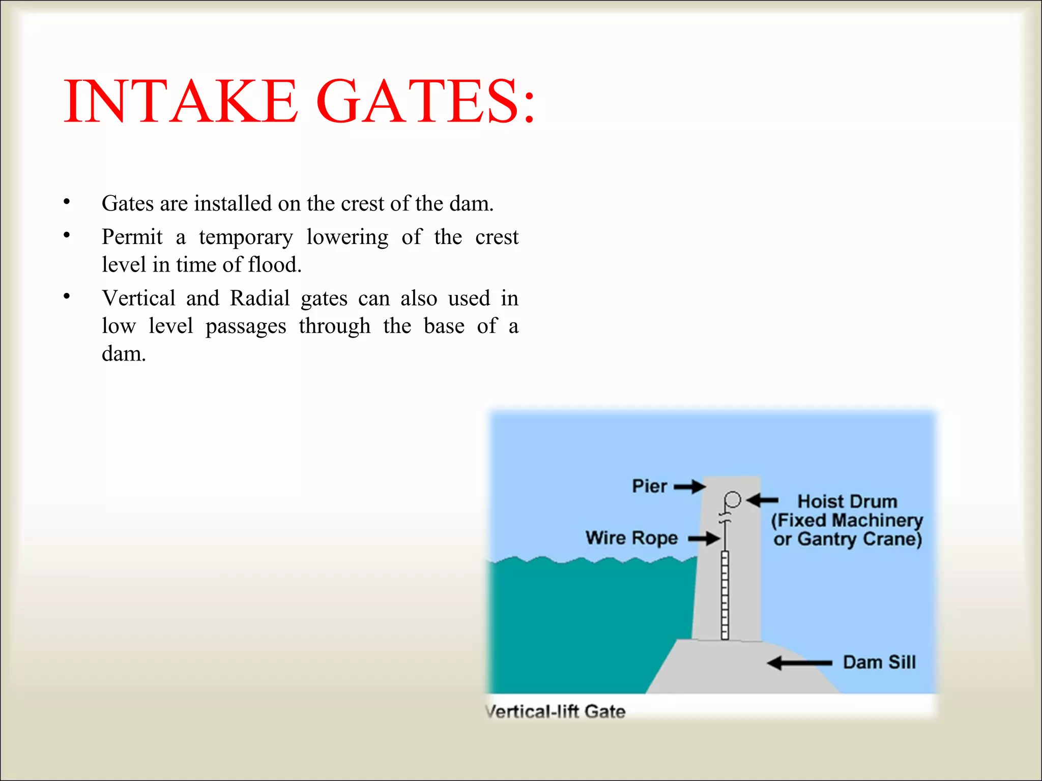


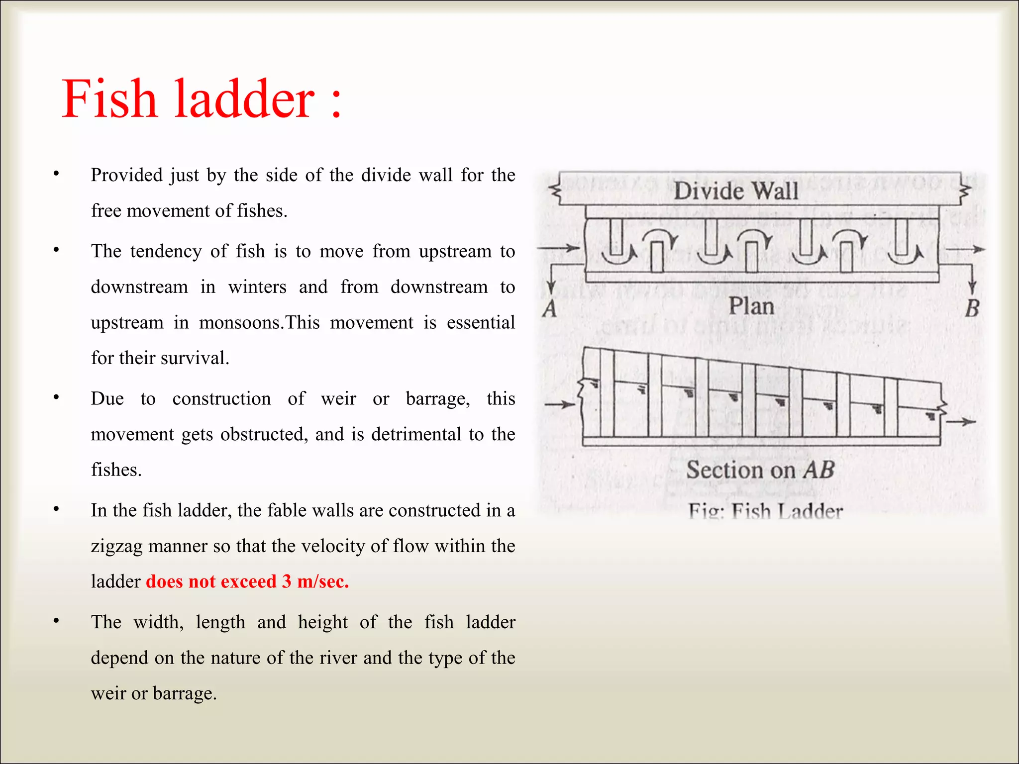


This document discusses the components and functions of intake structures at hydroelectric power plants. It begins by defining an intake as a structure that diverts water into a conduit leading to the power plant. The key components of intakes discussed include intake gates, trash racks and screens, fish ladders, ice and log booms, silt excluders and ejectors, smolt screens, under sluices, and divide walls. Intake gates such as vertical-lift and radial gates are used to control water flow. Trash racks and screens exclude debris while fish ladders allow fish to pass. Booms prevent ice and debris from blocking the intake. Silt excluders and ejectors remove silt from the