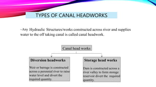
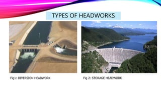
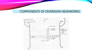
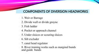
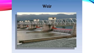
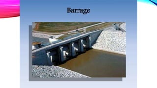
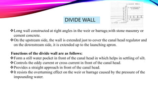
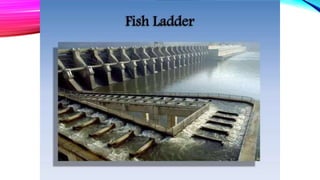
CHAPTER3:CANAL HEADWORKS
General
• The river discharge is never constant and regular. Obviously when a permanent canal system is
taken-off from the river some works are to be provided at the off-take to take care of irregularities
in river flow condition.
• Since these works are constructed at the point of takeoff that is at the head of the canal system they
are termed as canal headworks.
• The main object of the canal headworks is to divert the water from the river into the canal. It is
sometimes termed diversion headworks also.
• Canal Headwork is a civil engineering term for any hydraulic structure constructed across a
river and supplies water to the off taking canal.
• Any hydraulic structure which delivers water to off-taking canal is called a headwork.
TYPES OF CANAL HEADWORKS
–Any Hydraulic Structures/works constructed across river and supplies
water to the off taking canal is called canal headwork.
Canal head works
Diversion headworks
Weir or barrage is constructed
across a perennial river to raise
water level and divert the
required quantity.
Storage head works
Dam is constructed across a
river valley to form storage
reservoir divert the required
quantity.
TYPES OF HEADWORKS
Fig1: DIVERSION HEADWORK Fig 2: STORAGE HEADWORK
CANAL HEADWORKS
 Purposes:
– Raises water level in the river
– Regulates supply of water into the canal
– Controls the entry of silt into the canal
– Provides some storage for a short period
– Reduces the fluctuations in the level of supply in river
TYPES OF DIVERSION HEAD WORKS
 1. Temporary diversion head works
– Consists of a bund constructed across river to raise the
water level in the river and will be damaged by floods.
 2. Permanent diversion head works
– Consists of a permanent structure such as a weir or
barrage constructed across river to raise water level in
the river.
SITE SELECTION FOR DIVERSION HEAD WORK
• River section at the site should be narrow and well-defined.
• Should have a large commanded area.
• Site should be such that the weir (or barrage) can be aligned at right angles to the
direction of flow in the river.
• Good foundation should be available at the site.
• Site should be easily accessible by road or rail.
• Overall cost of the project should be a minimum.
COMPONENTS OF DIVERSION HEADWORKS
 1. Weir or Barrage
 2. Divide wall or divide groyne
 3. Fish ladder
 4. Pocket or approach channel
 5. Under sluices or scouring sluices
 6. Silt excluder
 7. canal head regulator
 8. River training works such as marginal bunds
and guide bunds
COMPONENTS OF DIVERSION HEADWORKS
WEIR OR BARRAGE
Weir is a structure constructed across river to raise the
water level and divert the water into the canal .Weir
aligned at right angle to the direction flow. Shutters are
provided at the crest of the weir so that part of raising
up of water is carried out by shutters.
DIVIDE WALL
Long wall constructed at right angles in the weir or barrage,with stone masonry or
cement concrete.
On the upstream side, the wall is extended just to cover the canal head regulator and
on the downstream side, it is extended up to the launching apron.
Functions of the divide wall are as follows:
Form a still water pocket in front of the canal head in which helps in settling of silt.
Controls the eddy current or cross current in front of the canal head.
Provides a straight approach in front of the canal head.
It resists the overturning effect on the weir or barrage caused by the pressure of the
impounding water.
FISH LADDER
Consists of an inclined channel with a slope not exceeding 1 in 10.
The compartment of bays of fish ladder should be sufficiently large so that the
fish do not collide with the sides of the bay when ascending.
Grooved gates are provided at the entrance and at the exit of the fish ladder for
closing it.
The water supply to the fish ladder should be adequate for the fish to travel at all
times.
UNDER SLUICES
Functions of under sluices:
Maintain a clear and well defined river channel in front of the headregulator.
Used to scour away the silt deposited in front of the head regulator.
They pass low floods without dropping the weir crest shutters.
They control the silt entry into the canal.
They provide greater waterway for floods, thus lowering the flood levels.
SILT EXCLUDER
 Device to exclude silt from water entering the canal.
Consists of a number of rectangular tunnels
The tunnels are of different lengths.
The length of the tunnels gradually decreases as the distance of the head regulator.
• Silt excluder is the structure provided
in still pocket to pass silt content
water in D/S .
• This is helps to allow clear water entry
in canal.
• Water contains silt is having high
density so it is always near to bed
level.
• The tunnel nearest to the head
regulator is longest, and the
successive tunnels decrease in length,
the tunnel nearest to the divide wall is
shortest.
• The tunnels are covered by R.C.C.
Slab.
• The top level of the slab is kept below
the sill level of the head regulator.
• So, the completely clear water is
allowed to flow in the canal through
the head regulator.
CANAL HEAD REGULATOR
Functions of Canal Head Regulator:
 It regulates the supply of water entering the canal.
 It prevents the river-floods from entering the canal
 The entry of silt into the canal is controlled
 Silt gets deposited in the pocket, and only the clear water enters the regulator
bays.
CANAL HEAD REGULATOR
Constructed at the head of canal to regulate flow.
Consists of a number of piers which divide the total width of the canal
into a number of spans which are known as bays.
The piers consist of number tiers on which the adjustable gates are
placed.
The gates are operated form the top by suitable mechanical device.
• Structure at the head of canal taking off from a reservoir may
consist of number of spans separated by piers and operated by
gates.
• Regulators are normally aligned at 90° to the weir.
• These are used for diversion of flow.
• Silt reduces carriage capacity of flow.
II. CANAL REGULATOR:
FUNCTIONS OF CANAL HEAD
REGULATORS
 Provides platform for bridges for communication facility.
 To maintain constant supply in off tacking canal during low
Discharge Period.
 To cut off the Discharge of parent canal during maintenance
on D/S side.

chapter-3.pptx: CHANNEL HEADWORKS AND CANALS

  • 1.
  • 2.
    General • The riverdischarge is never constant and regular. Obviously when a permanent canal system is taken-off from the river some works are to be provided at the off-take to take care of irregularities in river flow condition. • Since these works are constructed at the point of takeoff that is at the head of the canal system they are termed as canal headworks. • The main object of the canal headworks is to divert the water from the river into the canal. It is sometimes termed diversion headworks also. • Canal Headwork is a civil engineering term for any hydraulic structure constructed across a river and supplies water to the off taking canal. • Any hydraulic structure which delivers water to off-taking canal is called a headwork.
  • 3.
    TYPES OF CANALHEADWORKS –Any Hydraulic Structures/works constructed across river and supplies water to the off taking canal is called canal headwork. Canal head works Diversion headworks Weir or barrage is constructed across a perennial river to raise water level and divert the required quantity. Storage head works Dam is constructed across a river valley to form storage reservoir divert the required quantity.
  • 4.
    TYPES OF HEADWORKS Fig1:DIVERSION HEADWORK Fig 2: STORAGE HEADWORK
  • 5.
    CANAL HEADWORKS  Purposes: –Raises water level in the river – Regulates supply of water into the canal – Controls the entry of silt into the canal – Provides some storage for a short period – Reduces the fluctuations in the level of supply in river
  • 6.
    TYPES OF DIVERSIONHEAD WORKS  1. Temporary diversion head works – Consists of a bund constructed across river to raise the water level in the river and will be damaged by floods.  2. Permanent diversion head works – Consists of a permanent structure such as a weir or barrage constructed across river to raise water level in the river.
  • 7.
    SITE SELECTION FORDIVERSION HEAD WORK • River section at the site should be narrow and well-defined. • Should have a large commanded area. • Site should be such that the weir (or barrage) can be aligned at right angles to the direction of flow in the river. • Good foundation should be available at the site. • Site should be easily accessible by road or rail. • Overall cost of the project should be a minimum.
  • 8.
  • 9.
     1. Weiror Barrage  2. Divide wall or divide groyne  3. Fish ladder  4. Pocket or approach channel  5. Under sluices or scouring sluices  6. Silt excluder  7. canal head regulator  8. River training works such as marginal bunds and guide bunds COMPONENTS OF DIVERSION HEADWORKS
  • 10.
    WEIR OR BARRAGE Weiris a structure constructed across river to raise the water level and divert the water into the canal .Weir aligned at right angle to the direction flow. Shutters are provided at the crest of the weir so that part of raising up of water is carried out by shutters.
  • 15.
    DIVIDE WALL Long wallconstructed at right angles in the weir or barrage,with stone masonry or cement concrete. On the upstream side, the wall is extended just to cover the canal head regulator and on the downstream side, it is extended up to the launching apron. Functions of the divide wall are as follows: Form a still water pocket in front of the canal head in which helps in settling of silt. Controls the eddy current or cross current in front of the canal head. Provides a straight approach in front of the canal head. It resists the overturning effect on the weir or barrage caused by the pressure of the impounding water.
  • 17.
    FISH LADDER Consists ofan inclined channel with a slope not exceeding 1 in 10. The compartment of bays of fish ladder should be sufficiently large so that the fish do not collide with the sides of the bay when ascending. Grooved gates are provided at the entrance and at the exit of the fish ladder for closing it. The water supply to the fish ladder should be adequate for the fish to travel at all times.
  • 19.
    UNDER SLUICES Functions ofunder sluices: Maintain a clear and well defined river channel in front of the headregulator. Used to scour away the silt deposited in front of the head regulator. They pass low floods without dropping the weir crest shutters. They control the silt entry into the canal. They provide greater waterway for floods, thus lowering the flood levels.
  • 23.
    SILT EXCLUDER  Deviceto exclude silt from water entering the canal. Consists of a number of rectangular tunnels The tunnels are of different lengths. The length of the tunnels gradually decreases as the distance of the head regulator.
  • 24.
    • Silt excluderis the structure provided in still pocket to pass silt content water in D/S . • This is helps to allow clear water entry in canal. • Water contains silt is having high density so it is always near to bed level. • The tunnel nearest to the head regulator is longest, and the successive tunnels decrease in length, the tunnel nearest to the divide wall is shortest. • The tunnels are covered by R.C.C. Slab. • The top level of the slab is kept below the sill level of the head regulator. • So, the completely clear water is allowed to flow in the canal through the head regulator.
  • 25.
    CANAL HEAD REGULATOR Functionsof Canal Head Regulator:  It regulates the supply of water entering the canal.  It prevents the river-floods from entering the canal  The entry of silt into the canal is controlled  Silt gets deposited in the pocket, and only the clear water enters the regulator bays.
  • 26.
    CANAL HEAD REGULATOR Constructedat the head of canal to regulate flow. Consists of a number of piers which divide the total width of the canal into a number of spans which are known as bays. The piers consist of number tiers on which the adjustable gates are placed. The gates are operated form the top by suitable mechanical device.
  • 27.
    • Structure atthe head of canal taking off from a reservoir may consist of number of spans separated by piers and operated by gates. • Regulators are normally aligned at 90° to the weir. • These are used for diversion of flow. • Silt reduces carriage capacity of flow. II. CANAL REGULATOR:
  • 30.
    FUNCTIONS OF CANALHEAD REGULATORS  Provides platform for bridges for communication facility.  To maintain constant supply in off tacking canal during low Discharge Period.  To cut off the Discharge of parent canal during maintenance on D/S side.