Diversion headworks are structures constructed at the head of a canal to divert river water into the canal. They include weirs or barrages that raise the water level, as well as other components like canal head regulators, divide walls, fish ladders, and scouring sluices. The objectives of diversion headworks are to raise water levels, form water storage, control silt entry, and regulate water levels during different seasons. Key considerations for siting diversion headworks include river characteristics, elevation, foundation stability, and access for construction materials.
Topics:
1. Types of Diversion Head Works
2. Weirs and Barrages
3. Layout Diversion Head Works
4. Causes of Failures of Weirs and Barrages on Permeable Foundations
5. Silt Ejectors and Silt Excluders
Topics:
1. Types of Diversion Head Works
2. Weirs and Barrages
3. Layout Diversion Head Works
4. Causes of Failures of Weirs and Barrages on Permeable Foundations
5. Silt Ejectors and Silt Excluders
Types- selection of the suitable site for the diversion headwork components
of diversion headwork- Causes of failure of structure on pervious foundation- Khosla’s theory- Design of concrete sloping
glacis weir.
Canal fall- necessity and location- types of falls- Cross regulator and
distributory head regulator- their functions, Silt control devices, Canal
escapes- types of escapes.
This presentation covered Diversion head work topic. Details topics selection of the suitable site for the
diversion headwork- different parts of
diversion headwork- Causes of failure of
structure on pervious foundation- Khosla’s
theory- Design of concrete sloping glacis weir covered.
TYPES OF RIVER, PERENNIAL & NON PERENNIAL, PERENIAL V/S NON PERENIAL, STAGES OF RIVERS, RIVER STAGES COVERED, MEANDERING, CUT OFF, RIVER TRAINING WORKS, OBJECTIVE OF RIVER TRAINING, CLASSIFICATION OF RIVER TRAINING WORKS, TYPES OF RIVER TRAINING WORK, PICTURES
Canal Regulation Works:
Canal Fall- Necessity and Location- Types of Falls- Cross Regulator and Distributory Head Regulator- Their Functions, Silt Control Devices, Canal Escapes- Types of Escapes.
A water distribution system is a part of water supply network with components that carry potable water from a centralized treatment plant or wells to consumers to satisfy residential.
chapter-3.pptx: CHANNEL HEADWORKS AND CANALSmulugeta48
Purposes:
Raises water level in the river
Regulates supply of water into the canal
Controls the entry of silt into the canal
Provides some storage for a short period
Reduces the fluctuations in the level of supply in river
Temporary diversion head works
Consists of a bund constructed across river to raise the water level in the river and will be damaged by floods.
2. Permanent diversion head works
Consists of a permanent structure such as a weir or barrage constructed across river to raise water level in the river.River section at the site should be narrow and well-defined.
Should have a large commanded area.
Site should be such that the weir (or barrage) can be aligned at right angles to the direction of flow in the river.
Good foundation should be available at the site.
Site should be easily accessible by road or rail.
Overall cost of the project should be a minimum
Defination Headworks is a civil engineering term for any structure at the head or diversion point of a waterway. It is smaller than a barrage and is used to divert water from a river into a canal or from a large canal into a smaller canal.
Forklift Classes Overview by Intella PartsIntella Parts
Discover the different forklift classes and their specific applications. Learn how to choose the right forklift for your needs to ensure safety, efficiency, and compliance in your operations.
For more technical information, visit our website https://intellaparts.com
TECHNICAL TRAINING MANUAL GENERAL FAMILIARIZATION COURSEDuvanRamosGarzon1
AIRCRAFT GENERAL
The Single Aisle is the most advanced family aircraft in service today, with fly-by-wire flight controls.
The A318, A319, A320 and A321 are twin-engine subsonic medium range aircraft.
The family offers a choice of engines
Welcome to WIPAC Monthly the magazine brought to you by the LinkedIn Group Water Industry Process Automation & Control.
In this month's edition, along with this month's industry news to celebrate the 13 years since the group was created we have articles including
A case study of the used of Advanced Process Control at the Wastewater Treatment works at Lleida in Spain
A look back on an article on smart wastewater networks in order to see how the industry has measured up in the interim around the adoption of Digital Transformation in the Water Industry.
CFD Simulation of By-pass Flow in a HRSG module by R&R Consult.pptxR&R Consult
CFD analysis is incredibly effective at solving mysteries and improving the performance of complex systems!
Here's a great example: At a large natural gas-fired power plant, where they use waste heat to generate steam and energy, they were puzzled that their boiler wasn't producing as much steam as expected.
R&R and Tetra Engineering Group Inc. were asked to solve the issue with reduced steam production.
An inspection had shown that a significant amount of hot flue gas was bypassing the boiler tubes, where the heat was supposed to be transferred.
R&R Consult conducted a CFD analysis, which revealed that 6.3% of the flue gas was bypassing the boiler tubes without transferring heat. The analysis also showed that the flue gas was instead being directed along the sides of the boiler and between the modules that were supposed to capture the heat. This was the cause of the reduced performance.
Based on our results, Tetra Engineering installed covering plates to reduce the bypass flow. This improved the boiler's performance and increased electricity production.
It is always satisfying when we can help solve complex challenges like this. Do your systems also need a check-up or optimization? Give us a call!
Work done in cooperation with James Malloy and David Moelling from Tetra Engineering.
More examples of our work https://www.r-r-consult.dk/en/cases-en/
Immunizing Image Classifiers Against Localized Adversary Attacksgerogepatton
This paper addresses the vulnerability of deep learning models, particularly convolutional neural networks
(CNN)s, to adversarial attacks and presents a proactive training technique designed to counter them. We
introduce a novel volumization algorithm, which transforms 2D images into 3D volumetric representations.
When combined with 3D convolution and deep curriculum learning optimization (CLO), itsignificantly improves
the immunity of models against localized universal attacks by up to 40%. We evaluate our proposed approach
using contemporary CNN architectures and the modified Canadian Institute for Advanced Research (CIFAR-10
and CIFAR-100) and ImageNet Large Scale Visual Recognition Challenge (ILSVRC12) datasets, showcasing
accuracy improvements over previous techniques. The results indicate that the combination of the volumetric
input and curriculum learning holds significant promise for mitigating adversarial attacks without necessitating
adversary training.
COLLEGE BUS MANAGEMENT SYSTEM PROJECT REPORT.pdfKamal Acharya
The College Bus Management system is completely developed by Visual Basic .NET Version. The application is connect with most secured database language MS SQL Server. The application is develop by using best combination of front-end and back-end languages. The application is totally design like flat user interface. This flat user interface is more attractive user interface in 2017. The application is gives more important to the system functionality. The application is to manage the student’s details, driver’s details, bus details, bus route details, bus fees details and more. The application has only one unit for admin. The admin can manage the entire application. The admin can login into the application by using username and password of the admin. The application is develop for big and small colleges. It is more user friendly for non-computer person. Even they can easily learn how to manage the application within hours. The application is more secure by the admin. The system will give an effective output for the VB.Net and SQL Server given as input to the system. The compiled java program given as input to the system, after scanning the program will generate different reports. The application generates the report for users. The admin can view and download the report of the data. The application deliver the excel format reports. Because, excel formatted reports is very easy to understand the income and expense of the college bus. This application is mainly develop for windows operating system users. In 2017, 73% of people enterprises are using windows operating system. So the application will easily install for all the windows operating system users. The application-developed size is very low. The application consumes very low space in disk. Therefore, the user can allocate very minimum local disk space for this application.
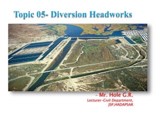
1. - Mr. Hole G.R.
Lecturer-Civil Department,
JSP,HADAPSAR
2. The works which are constructed at the head of the canal
in order to divert the river water toward the canal, so as
to ensure a regulated continuous supply mostly silt free
water with certain minimum head into the canal, are
known as diversion headworks.
3. Storage Headwork :
A storage Headwork is structure( Dam) which is constructed
across river to store water during excess inflow and used to
supply during less inflow and high Demand.
Diversion Headwork:
It is structure which constructed across river (Weir) to raise the
water level in river so that it can diverted in to canal system.
4. The Following are the objective of Diversion Head works
To Raise the water level at the head of canal.
To form a storage by construction of dykes on both
side of banks of the river so that water is available
throughout the year.
To control the entry of silt into the canal and to
control the deposition of silt at the head of canal.
To control the fluctuation of water level in the river
during different seasons.
5. The following points should be considered to select a
site for this diversion headworks.
The river should be straight and narrow at the site
The elevation of site should be higher than the area to
be irrigated for gravity flow.
River banks at site should be well defined and stable.
Valuable land upstream of the barrier like weir or
barrage should not be submerged.
6. Material of construction should be locally available.
Roads or railway communication to the site is essential
to carry the material of construction.
Site should be close to the cropland to minimize loss of
water due to seepage and evaporation of canal.
The site should provide a good foundation for
construction of weir or barrage.
7.
8. The components of diversion headworks are:
Weir or barrage
Canal head regulator
Divide Wall
Fish Ladder
Scouring Sluices Under sluices
Silt excluder
Silt ejector.
Marginal embankment or dikes
Guide bank
Silt pocket or trap.
9. 1.Weir
It is a solid obstruction placed across the river. Its main
function is to raise the water level so that water can be
diverted by canal to crop field due to difference of head.
10.
11. Barrage is practically a low weir with an adjustable
gate over this low weir. Heading up of water is
affected by gate.
12.
13.
14. 1.Vertical Drop Weir(Masonry Weir)
A crest gate may be provided to store more water
during flood period.
At the upstream and downstream ends of impervious
floor cut off piles are provided.
Launching apron are provided both at upstream and
downstream ends of floor to safeguard against
scouring action.
A graded filter is provided immediately at the
downstream end of impervious floor to relieve the
uplift pressure.
This type of weir is suitable for any type of
foundation.
15.
16. This type is suitable for soft sandy foundation.
It is used where difference in weir crest and
downstream river bed is not more than 3 m.
Hydraulic jump is formed when water passes over the
sloping glacis.
Suitable for soft soil foundation.
17. In rock fill type weir, there are no of core wall on D/S of main
weir wall and space between weir wall is filled with rock
fragments that’s why it is called as Rock fill Weir.
Requires large quantity of rock fragments so it is economical
when rock are available easily in surrounding region.
Suitable for fine sand foundation.
18. Structure at the head of canal taking off from a reservoir may
consist of number of spans separated by piers and operated by
gates.
Regulators are normally aligned at 90° to the weir.
These are used for diversion of flow.
Silt reduces carriage capacity of flow.
19. Provides platform for bridges for communication facility.
To maintain constant supply in off tacking canal during
low Discharge Period.
To cut off the Discharge of parent canal during
maintenance on D/S side.
20. The Divide Wall is a long wall constructed at right angle to
the weir or barrage, it may be constructed with stone masonry
or cement concrete.
On the upstream side, the wall is extended just to cover the
canal regulator and on the down stream side, it is extended up
to the launching apron.
The functions of the divide wall are as follows,
1. To form a still water pocket in front of the canal head so that
the suspended silt can be settled down which then later can be
cleared through the scouring sluices from time to time.
2. It controls the eddy current or cross current in front of the canal
head.
3. It provides a straight approach in front of the canal head.
4. It resists the overturning effect on the weir or barrage caused by
the pressure of the impounding water.
21. The Scouring sluices are the openings provided at the
base of the weir or barrage at lower level.
It is provided at same side on which off tacking canal
is located.
The crest of under sluices is kept lower than crest of
weir due to which water is attracted towards sluice
which helps to easy diversion of water in to canal.
22. The Fish Ladder is passage provided adjacent to divide
wall for the movement of fishes from U/S to D/S and
vice-versa.
In general, the tendency of fish is to move from
upstream to downstream in winters and from
downstream to upstream in monsoons. This movement
is essential for their survival.
In the fish ladder, the baffle walls are constructed in
the zigzag manner so that the velocities of flow within
the ladder does not exceed 3 m/s
23.
24. Silt excluder is the structure
provided in still pocket to pass silt
content water in D/S .
This is helps to allow clear water
entry in canal.
Water contains silt is having high
density so it is always near to bed
level.
The tunnel nearest to the head
regulator is longest, and the
successive tunnels decrease in
length, the tunnel nearest to the
divide wall is shortest.
The tunnels are covered by R.C.C.
Slab.
The top level of the slab is kept
below the sill level of the head
regulator.
So, the completely clear water is
allowed to flow in the canal
through the head regulator.
25. Silt ejectors, also called silt
extractors, are those devices
which extract the silt from the
canal water after the silted
water has traveled a certain
distance in the off-take canal.
These works are, therefore,
constructed on the bed of the
canal, and little distance
downstream from the head
regulator.
It consist of tunnels parallel to
flow of canal and turns in to 90
to eject silt.
The length provided may be
different.