Downloaded 1,359 times


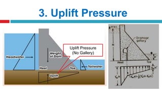

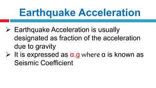


The document provides an overview of gravity dams, detailing their types, advantages, disadvantages, forces acting on them, and potential causes of failure. It emphasizes the structural stability required for effective design, including profiles and conditions affecting performance. Additionally, it includes practical considerations such as drainage galleries and maintenance requirements.