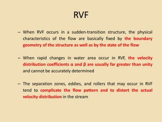
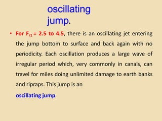
2. contents
• Introduction
• Definition and Types of Hydraulic Jump
• Definition
• Types of Hydraulic Jump
• Hydraulic Jump in a Horizontal Rectangular Channel
• Basic Characteristics of Hydraulic Jump
• Hydraulic Jumps in Horizontal non-rectangular Channel
• Hydraulic Jumps as Energy Dissipater
3.
4. RVF
– When RVF occurs in a sudden-transition structure, the physical
characteristics of the flow are basically fixed by the boundary
geometry of the structure as well as by the state of the flow
– When rapid changes in water area occur in RVF, the velocity
distribution coefficients α and β are usually far greater than unity
and cannot be accurately determined
– The separation zones, eddies, and rollers that may occur in RVF
tend to complicate the flow pattern and to distort the actual
velocity distribution in the stream
5. hydraulic jump
A hydraulic jump is a phenomenon in the
science of hydraulics which is frequently
observed in open channel flow such as rivers
and spillways. When liquid at high velocity
discharges into a zone of lower velocity, a
rather abrupt rise occurs in the liquid surface.
The rapidly flowing liquid is abruptly slowed
and increases in height, converting some of
the flow's initial kinetic energy into an
increase in potential energy, with some
energy irreversibly lost through turbulence to
heat. In an open
6.
7. Hydraulic jump
supercritical flow changes to subcritical flow
–water surface rises abruptly,
–surface rollers are formed,
–intense mixing occurs,
–air is entrained, and usually a large amount of energy is dissipated
8. Practical applications of the
hydraulic jump
• To dissipate energy in water flowing
• To recover head or raise the water level
• To increase the weight on an apron and thus
reduce uplift pressure
• To increase the discharge of a sluice by
holding back tail-water
• To mix chemicals
• To aerate the water
9. Types of Hydraulic
Jump
• Based of the Froude number hydraulic jumps
are classified as
• For Fr1 = 1, the flow is critical, and hence no
jump can form.
10.
11. undular
Jump
• For Fr1 = 1 to 1.7, the water surface shows
undulations, and the jump is called an
undular Jump.
12.
13.
14.
15. weak
jump
• For Fr1 = 1.7 to 2.5, a series of small rollers
develop on the surface of the jump, but the
d/s water surface remains smooth. The
uniform. This
velocity throughout
jump is called a
weak jump
is fairly
16.
17. oscillating
jump.
• For Fr1 = 2.5 to 4.5, there is an oscillating jet entering
the jump bottom to surface and back again with no
periodicity. Each oscillation produces a large wave of
irregular period which, very commonly in canals, can
travel for miles doing unlimited damage to earth banks
and ripraps. This jump is an
oscillating jump.
18.
19. steady
jump
• For Fr1 = 4.5 to 9.0, the downstream extremity of the
surface roller and the point at which the high-velocity jet
tends to leave the flow occur at practically at the same
vertical section. The action and position of this jump are
least to variation in tail-water depth. The jump is well-
balanced and the performance is at its best. The energy
dissipation ranges from 45 to 70%. This jump is called a
steady jump
20.
21. strong jump
• For Fr1 = 9.0 and larger, the high-velocity jet grabs
intermittent slugs of water rolling down the front
face of the jump, generating waves downstream,
and a rough surface can prevail. The jump action
is rough but effective since the energy dissipation
may reach 85%. This jump is called a
strong jump
22.
23. Hydraulic Jump in a
Horizontal Rectangular
Channel
• In most open channel flow problems involving jumps, one of the two depths y1 or y2 would be
known, and we need to calculate the second one.
• Because the energy loss due to hydraulic jump is usually significant and unknown, we cannot use
the energy equation to determine the unknown depth rather we use the momentum equation is
written between the two sections.
– Considering a horizontal rectangular open channel of constant channel width B
– neglecting the shear stress at the channel bottom,
– the resultant of the forces acting in the longitudinal direction are the result of hydrostatic pressure at the
ends of the control volume
24. Basic Characteristics of Hydraulic
Jump
• Sequent depth ratio
or
• Energy Loss
or
The ratio ∆E/E1 is known as the relative loss
• Efficiency : The ratio of the specific energy after the jump to that before the jump is
defined as the efficiency of the jump. It is given by
This equation indicates that the efficiency of a jump is a dimensionless function,
depending only on the Froude number of the approaching flow. The relative loss
is equal to 1 – E2/E1. It is also a dimensionless function of Fr1.
25. Basic Characteristics of Hydraulic
Jump
• Height of Jump : The difference between the depths after and
before the jump is the height of the jump, or hj = y2 – y1.
• If it is expressing as a ratio with respect to the initial specific energy, it is
known the relative height
or
• Length of a Jump : may be defined as the distance measured from
the front face of the jump to a point on the surface immediately d/s from
the roller. This length cannot be determined easily by theory, but has
been investigated experimentally
• The experimental data on Lj can be plotted conveniently with Fr1 against
dimensionless ratios L/(y2 – y1), L/y1, or L/y2. For practical purposes,
however, the plot of Fr1 Vs L/y2 is desirable,
• Thus the experimental determination of
f(F1)=Lj /y2 for higher value of F1 > 5.0,
the relative Jump length Lj/y2 become constant
and it can be estimated Lj = 6.9(y2-y1)
26.
27. Basic Characteristics of Hydraulic
Jump
Profile of the Jump
• The jump profile is required to determine the weight of water in a dissipater in
order to counteract the uplift force if the basin floor is laid on a permeable
foundation. While designing the height of the side walls, the water profile is
required.
• Bakhmetoff and Metzke who were the first to investigate systematically the
longitudinal elements of the jump, took the end of the jump as the section of
maximum surface elevation before the drop off caused by the channel conditions
downstream.
• They also represented the surface profile of the jump by dimensionless curves for
various F1 values.
• Hager [1991a] developed the following empirical relationship for the flow depth, y,
at distance, x, from the beginning of the jump
28. Basic Characteristics of Hydraulic
Jump
• Subramanya and Rajaratnam have shown that the jump profile can be expresses in
non-dimensional manner as
and
Where X is the length scale defined as the value of x at which
The coordinates of the profile are (x, h) with the boundary condition that x=0, at h=0
and x=Lj at h= (y2 - y1). In general, h= f(x, F1)
29. Example
6.1: The rectangular channel shown in the figure below is nearly
horizontal, and it carries a discharge, q = 0.95m3/s/m. The flow
depth upstream of the sluice gate is 1.5 m. A hydraulic jump occurs
on the downstream side of the sluice gate. Determine the flow
depth at sections B and D, and the energy loss due to the jump.
30. Hydraulic Jumps in
Horizontal non-rectangular
Channel
• The jump in such channels is characterized by a lateral expansion of the jet (if
the channel width is increasing from bottom to top as is usually the case) in
addition to the expansion in the vertical direction
• The conjugate depth ratio in trapezoidal, parabolic, and triangular channels is
less than that of a rectangular channel at the same Froude number.
• Considering a frictionless, horizontal prismatic channel, in the absence of
external forces (except the pressure force) the momentum equation between
the toe and the heel (or between sections 1 and 2) of the jump can be written
as
P1- P2 = M1 - M2 =
• Where A =area of cross section y= depth of the center of gravity of the area
Re arrange P1+M1 = P2M2 = Constant = P +M
• Where Ps is the specific momentum (force)
– This equation is valid provided that the pressure distributions at sections 1 and 2 are
hydrostatic.
– Thus, for a given channel shape, Q and y1, the value of M1 can be calculated. The value of
y2 which makes M2 equal to M1 can then be determined by trial-and-error.
Q2V2 Q1V1
2
1
A1 y A2 y
32. Example 6.2
The trapezoidal channel has a bottom width of B = 1.80 m,
side slopes of m = 2, and it carries a discharge of 8.5 m3/s.
A hydraulic jump occurs in this channel. The flow depth
just before the jump is y1 = 0.30 m. Determine the depth
after the jump.
33. Hydraulic Jumps as
Energy Dissipater
• From a practical viewpoint, hydraulic jump is a useful means of dissipating
excess energy in supercritical flow.
– Its merit is in preventing possible erosion below overflow spillways, chutes, and sluices,
for it quickly reduces the velocity of the flow on the paved apron to a point where the flow
becomes incapable of scouring the downstream channel bed.
• The hydraulic jump used for energy dissipation is usually confined partly or
entirely to a channel reach known as the stilling basin.
• In practice, the stilling basin is designed with accessories to control the
jump in the basin.
– These accessories shorten the range within which the jump will take place and hence reduce the
cost.
– They also improve the dissipation function of the basin and stabilize the jump.
• Position of Hydraulic Jump: Hydraulic jump is formed at a location where the
flow depths upstream and downstream of the jump satisfy the equation for
the sequent depth ratio.
• Let the flow depth at the sluice outlet be y1 and the sequent depth
corresponding to this depth be y2. There are several different possibilities for
the formation of jump, depending upon on the tailwater depth, yd.
34.
35.
36.
37. Hydraulic Jumps as
Energy Dissipater
• Case A : Tail-water depth (yd) equal to the sequent depth (y2)
– It is an ideal one for scour protection purposes.
– needs device to control the position of the jump
• Case B : Tail-water depth (yd) less than the sequent depth (y2)
– Jump repelled from the scour-resisting apron
– It should be avoided in design
• Case C : Tail-water depth (yd) grater than the sequent depth (y2)
– The jump forced to upstream and becoming a submerged jump
– It is the safest case in design
38. Hydraulic Jumps as Energy
Dissipater
• Tail-water Conditions: Tail-water level plays a significant role in the
formation of jump at a particular location.
• The tail-water fluctuates owing to changes in discharge in the channel.
• The tail-water rating curve is usually available as a relation between
tail-water stage yd and discharge Q.
• In a similar way, a jump rating curve may be constructed to show the
relation between the sequent depth y2 and Q.
• Depending upon these two curves, five different flow situations are
possible.
39.
40. Hydraulic Jumps as Energy
Dissipater
• Class A: represents the ideal condition in which the two rating curves always coincide. This means
the jump forms at the desired place on the apron at all discharges.
• Class B: In this case the jump forms at a certain place far downstream. An effective method of ensuring
that the jump will occur on the protected apron is to use sills to create a stilling basin.
• Class C: The jump may be controlled at the desired location by providing a drop in the channel bottom
or by letting the jump form on a sloping apron.
• Class D: The tail-water curve is below the jump curve at low discharges and above it for higher
discharges. The stilling basin may be designed so that the jump is formed in the basin at low rates of
discharges and the jump moves on to a sloping apron at higher discharges.
• Class E: This is opposite to case (d) in the sense that the tail-water curve is above the jump curve at
low discharges and below the jump curve at high discharges. An effective method to ensure a jump is
to increase the tail-water depth sufficiently high by providing a stilling pool, thus forming a jump at
high discharges.
41.
42. Exercise 1
q=10m3/s/m and y1=1.25m. If
theflow undergoes a
hydraulic jump, compute
– sequent depth (y2)
– Velocity at sequent section (v2)
– Froude number at sequent (F2)
– Dissipation loss (hf)
– The percentage of dissipation
– The power dissipated per unit width
– The tempreture rise due to
• Water flows in wide rectangular channel of