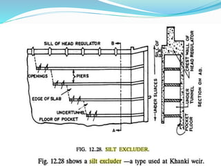
A little flashlight
 How Silt Regulation works
 The entry of silt into a canal, which takes off from a
head works, can be reduced by constructed certain
special works, called silt control works.
 These works may be classified into the following
two types:
 (a) Silt Excluders
 (b) Silt Ejectors
 (a) Silt Excluders
Silt excluders
 The idea of the silt excluder was first presented by
Elsdon in his
 Irrigation Branch Paper No.5 of 1922. The first silt
excluder was
 designed by Nicolson at Khanki head works in 1934 as
shown in Figure.
 The basic idea behind the design is that the lower
layers of the flowing water carry a higher
concentration of silt and therefore if the upper layers
of the water only can be skimmed into the canal, all
the rolling bed silt and the silt in the lower layers is
excluded.
 This is achieved by a silt excluder. This is a diaphragm
slab supported on a number of tunnels. Tunnels are
placed parallel to the head regulator and discharge d/s
through the under sluice. The water above the silt
excluder slab containing less silt is then diverted into
the canal. The following points should be kept in mind
while designing a silt excluder:
 i) The tunnel discharge through the undersluice is
recommended to be 20 per cent of the canal discharge.
 ii) The silt excluder should cover only two bays of the
undersluice as this was found to be more efficient in
the model studies of Kalabagh barrage than a silt
excluder covering four bays.
 iii) The approach channel need not be lined.
 iv) The divide wall should be 1.2 to 1.4 times the head
regulator length.
 v) The top of the silt excluder slab should be flushed
with the head regulator crest, i.e. the clear height of
the tunnels would be 1/3 the depth of the water minus
the slab thickness.
 vi) The roof slab should be designed to carry a full
water load in case the tunnels are empty.
 vii) The first tunnel should cover completely the head
regulator, the other tunnels should be of shorter
lengths.
 viii)The discharge through the tunnels will depend
upon the head measured above the centre line of the
tunnel. Tunnels can be treated as box culverts.
Principles of Silt Control
 Before we describe the mechanism and functioning of
these silt control devices, we shall explain the basic
principle on which the silt is removed from the water.
 The fundamental principal the behind silt control is :
that most of the silt tries to settle down in water, thus,
confining itself mostly in the bottom layers of water.
 We also know that the silt is kept in suspension by the
force of the vertical eddies generated by the friction of
the flowing water against the bed.
 In other words, if this bed friction is more, the upward
force of eddies shall be more, and hence, lesser
chances of silt settlement wiII exist.
 Hence, if the friction can be reduced by constructing a
smooth approach channel, more settlement of silt and
its consequent removal, is possible. Further, the silt
from the bottom layers can be removed, by separating
the top layers and the bottom layers, without causing
any disturbance to the flow.
 The chances of less disturbance and that of providing a
smooth approach channel can be better attained in a canal
rather than in the river bed.
 Hence, the works which are constructed in the canal (i.e.
the silt extractors or silt ejectors) will definitely be superior
and more effective than the works which are constructed in
the river bed (i.e the silt excluders).
 Silt extractor is therefore, better than a silt excluder.
 However, the silt extractor shall be costlier because surplus
water has to be taken into the canal' from the head, and an
escape, channel which will feed the highly silted water
back into the river, shall have to be constructed.
Description and Design of a Silt
Excluder
 A silt excluder consists of a number of rectangular
tunnels running parallel to the caxisohhe head
regulator and terminating near the under-sluiced weir.
The tunnel nearest to the crest of the head regulator
has to be at least of the same length as the head
regulator. Other tunnels may be shorter in length. The
roof slab of the excluder tunnels is kept at the same
level as that of the regulator crest, as shown in Figure.
 The bottom layer of water which is highly charged
with silt and sediment will pass down the tunnels and
escape over the floor of the under-sluice way(s), since
the gates of the under sluice way(s) shall be kept open
upto the top of the tunnels. The clearer water over the
top of the roof of the excluder tunnels, will thus enter
the canal through the head regulator.
 Usually , two or three bays of the 'under-sluices of the
weir or the barrage are covered by the excluder.
 However, excluder covering only one bay has been
designed and is usually adopted for sandy rivers.
Factors effecting the efficiency of
silt excluders
 i) An increase in escape supply increases the efficiency
to a certain point but further increases in escape
supply may not increase the efficiency substantially.
 ii) The grade of sediment affects the efficiency. For
coarser silt the efficiency is more. For smaller grades it
is less.
Silt excluders

Silt excluders

  • 6.
    A little flashlight How Silt Regulation works  The entry of silt into a canal, which takes off from a head works, can be reduced by constructed certain special works, called silt control works.  These works may be classified into the following two types:  (a) Silt Excluders  (b) Silt Ejectors  (a) Silt Excluders
  • 7.
    Silt excluders  Theidea of the silt excluder was first presented by Elsdon in his  Irrigation Branch Paper No.5 of 1922. The first silt excluder was  designed by Nicolson at Khanki head works in 1934 as shown in Figure.
  • 9.
     The basicidea behind the design is that the lower layers of the flowing water carry a higher concentration of silt and therefore if the upper layers of the water only can be skimmed into the canal, all the rolling bed silt and the silt in the lower layers is excluded.  This is achieved by a silt excluder. This is a diaphragm slab supported on a number of tunnels. Tunnels are placed parallel to the head regulator and discharge d/s through the under sluice. The water above the silt excluder slab containing less silt is then diverted into the canal. The following points should be kept in mind while designing a silt excluder:
  • 10.
     i) Thetunnel discharge through the undersluice is recommended to be 20 per cent of the canal discharge.  ii) The silt excluder should cover only two bays of the undersluice as this was found to be more efficient in the model studies of Kalabagh barrage than a silt excluder covering four bays.  iii) The approach channel need not be lined.  iv) The divide wall should be 1.2 to 1.4 times the head regulator length.
  • 11.
     v) Thetop of the silt excluder slab should be flushed with the head regulator crest, i.e. the clear height of the tunnels would be 1/3 the depth of the water minus the slab thickness.  vi) The roof slab should be designed to carry a full water load in case the tunnels are empty.  vii) The first tunnel should cover completely the head regulator, the other tunnels should be of shorter lengths.  viii)The discharge through the tunnels will depend upon the head measured above the centre line of the tunnel. Tunnels can be treated as box culverts.
  • 12.
    Principles of SiltControl  Before we describe the mechanism and functioning of these silt control devices, we shall explain the basic principle on which the silt is removed from the water.  The fundamental principal the behind silt control is : that most of the silt tries to settle down in water, thus, confining itself mostly in the bottom layers of water.  We also know that the silt is kept in suspension by the force of the vertical eddies generated by the friction of the flowing water against the bed.
  • 13.
     In otherwords, if this bed friction is more, the upward force of eddies shall be more, and hence, lesser chances of silt settlement wiII exist.  Hence, if the friction can be reduced by constructing a smooth approach channel, more settlement of silt and its consequent removal, is possible. Further, the silt from the bottom layers can be removed, by separating the top layers and the bottom layers, without causing any disturbance to the flow.
  • 14.
     The chancesof less disturbance and that of providing a smooth approach channel can be better attained in a canal rather than in the river bed.  Hence, the works which are constructed in the canal (i.e. the silt extractors or silt ejectors) will definitely be superior and more effective than the works which are constructed in the river bed (i.e the silt excluders).  Silt extractor is therefore, better than a silt excluder.  However, the silt extractor shall be costlier because surplus water has to be taken into the canal' from the head, and an escape, channel which will feed the highly silted water back into the river, shall have to be constructed.
  • 15.
    Description and Designof a Silt Excluder  A silt excluder consists of a number of rectangular tunnels running parallel to the caxisohhe head regulator and terminating near the under-sluiced weir. The tunnel nearest to the crest of the head regulator has to be at least of the same length as the head regulator. Other tunnels may be shorter in length. The roof slab of the excluder tunnels is kept at the same level as that of the regulator crest, as shown in Figure.
  • 17.
     The bottomlayer of water which is highly charged with silt and sediment will pass down the tunnels and escape over the floor of the under-sluice way(s), since the gates of the under sluice way(s) shall be kept open upto the top of the tunnels. The clearer water over the top of the roof of the excluder tunnels, will thus enter the canal through the head regulator.  Usually , two or three bays of the 'under-sluices of the weir or the barrage are covered by the excluder.  However, excluder covering only one bay has been designed and is usually adopted for sandy rivers.
  • 18.
    Factors effecting theefficiency of silt excluders  i) An increase in escape supply increases the efficiency to a certain point but further increases in escape supply may not increase the efficiency substantially.  ii) The grade of sediment affects the efficiency. For coarser silt the efficiency is more. For smaller grades it is less.