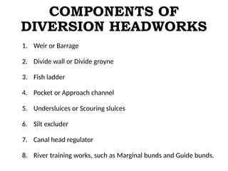
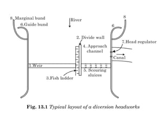
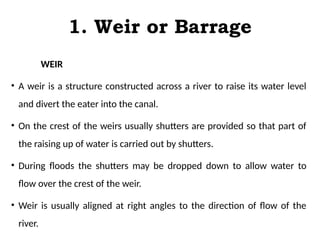
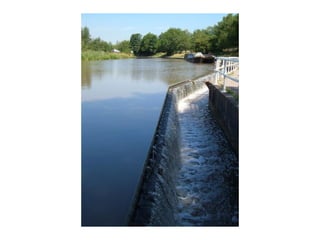
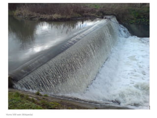
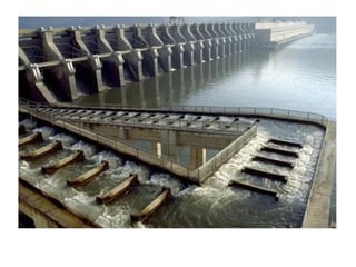
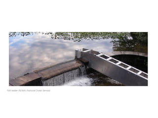
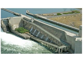
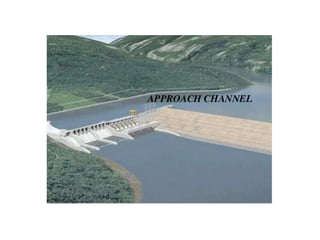
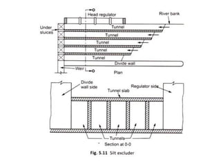
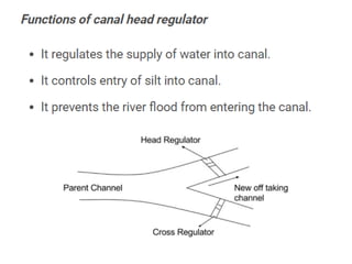
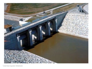
DESIGN OF HYDRAULIC
STRUCTURES
MODULE 1 LECTURE 2
PREPARED BY,
RESHMY M. RAJU
M.TECH ENV. ENGG.
TOPIC : Layout and functions of components
COMPONENTS OF
DIVERSION HEADWORKS
1. Weir or Barrage
2. Divide wall or Divide groyne
3. Fish ladder
4. Pocket or Approach channel
5. Undersluices or Scouring sluices
6. Silt excluder
7. Canal head regulator
8. River training works, such as Marginal bunds and Guide bunds.
1. Weir or Barrage
WEIR
• A weir is a structure constructed across a river to raise its water level
and divert the eater into the canal.
• On the crest of the weirs usually shutters are provided so that part of
the raising up of water is carried out by shutters.
• During floods the shutters may be dropped down to allow water to
flow over the crest of the weir.
• Weir is usually aligned at right angles to the direction of flow of the
river.
1. Weir or Barrage
WEIR
• Weirs may be classified according to the material of construction
and certain design features into the following three types.
1. Masonry weirs with vertical drop or vertical drop weirs.
2. Rockfill weirs with sloping aprons.
3. Concrete weirs with a downstream glacis
1. Weir or Barrage
BARRAGE
• In the case of a barrage the crest is kept at a low level and the raising
up of water level (or ponding) is accomplished mainly by means of
gates.
• During floods these gates can be raised clear off the high flood level
and thus enable the high flood to pass with minimum of afflux (or
heading up of water on the upstream side).
• A barrage provides better control on the water level in the river but it
is comparatively more costly.
2. DIVIDE WALL OR
DIVIDE GROYNE
• A divide wall is a long masonry or concrete wall or groyne (an
embankment protected on all sides by stone or concrete blocks) which is
constructed at right angles to the axis of the weir to separate the
undersluices from the rest of the weir.
• If two canals take off, one on either side of the river, then two divide walls
are required, one on each side.
• The top width of the divide wall is about 1.5 to 2.5m. The divide wall
extends on the upstream side up to a distance little beyond the beginning
of the canal head regulator and on the downstream side up to the end of
the loose protection.
3. FISH LADDER
• Large rivers have various types of fish, many of which are migratory.
• They move from one part of the river to another according to the season.
• In our country generally fish move from upstream to downstream in the
beginning of winter in search of warmth and return upstream before
monsoon for clearer water.
• Due to the construction of a weir or barrage across the river such
migration of the fish will be obstructed and if no arrangement is made in
the weir or barrage for this migration, large scale destruction of the fish
life may take place in the river.
3. FISH LADDER
• Thus to enable the fish to migrate fish ladder is provided.
• Since most fish can travel upstream only if the velocity of flow
does not exceed 3 to 3.5 m/s, the design of the fish ladder should
be such that it constantly releases water at a velocity not
exceeding this value.
4. POCKET OR
APPROACH CHANNEL
• The velocity of the river water should be reduced, when it reaches to the
canal head regulator when the velocity reduces, the silt particles which are
in suspension will settle down & clean water may enter the canal.
• To reduce the entry of silt into the canal, the floor level of the upstream side
is so adjusted that a pocket is made in front of the canal head regulator.
• In this pocket, the silt settles down, and the canal draws water from the still
pond of the pocket.
• This pocket is known as an approach channel, which is made with the help
of a divide wall.
5. UNDERSLUICES OR
SCOURING SLUICES
• The undersluices are the openings provided in the weir wall with
their crest at a low level.
• These openings are fully controlled by gates. They are located on
the same side as the off taking canal.
• If two canals take off, one on either side of the river, then it would
be necessary to provide undersluices on either side of the canal.
6. SILT EXCLUDER
• Silt excluders are a type of silt control device which functions to
exclude silt from water to entering the canal.
• These devices are particularly provided on the river bed in front of
the head regulator.
• A silt excluder usually consists of a number of rectangular tunnels
resting on the floor of the undersluice pocket.
• The bottom portion of the tunnels is formed by the floor of
undersluice pocket.
6. SILT EXCLUDER
• The top level portion of the roof of tunnel is kept same as the
level of the crest or sill of the head regulator.
• The tunnels are constructed with variable lengths.
• The tunnel nearest to the crest is of same length as the length of
the head regulator.
• But all other successive tunnels have a decreasing length.
7. CANAL HEAD
REGULATOR
• It is a structure constructed at the head of a canal from the
upstream of the weir or barrage constructed.
• It consists of number of spans separated by piers which supports
the gates provided for the regulation of water flow to the canal.
• The spans ranging from 6 to 8 m are used with counterbalanced
steel gates which are operated manually by winches.
• Also larger spans are used if necessary or the condition is
economical.
8. RIVER TRAINING
WORKS
• River training is defined as the various measure adopted on a river
to stabilize the river channel along a certain cross section for a
particular alignment.
• These measures are adopted because the rivers in alluvial plane
frequently alter their courses and subsequently cause damage to
the land and property adjacent to them.
• Some of the major river training works are explained as below:
• MARGINAL BUNDS
• GUIDE BANKS
8. RIVER TRAINING
WORKS
Marginal bunds
• Marginal bunds or levees are the earthen embankments which
are provided to confine the flood water from the river within an
allowable cross-section and in between the embankments.
• Thus the spreading of flood water beyond these marginal bunds is
prevented.
Guide banks or Guide bunds
• The guide bunds are also a type of earthen embankments provided to
confine the flood water of alluvial rivers within a reasonable length of
waterway and provide a straight and non-tortuous approach towards
the constructions works across the river.
• They are also used to prevent the river from changing its course and
outflanking the construction work. In India the guide banks were first
designed by Bell and hence these are also known as Bell’s bunds.
• The initial design by Bell was later modified by Spring and Gales and
this modified design is commonly adopted these days.
Layout and functions of components explained

Layout and functions of components explained

  • 1.
    DESIGN OF HYDRAULIC STRUCTURES MODULE1 LECTURE 2 PREPARED BY, RESHMY M. RAJU M.TECH ENV. ENGG. TOPIC : Layout and functions of components
  • 2.
    COMPONENTS OF DIVERSION HEADWORKS 1.Weir or Barrage 2. Divide wall or Divide groyne 3. Fish ladder 4. Pocket or Approach channel 5. Undersluices or Scouring sluices 6. Silt excluder 7. Canal head regulator 8. River training works, such as Marginal bunds and Guide bunds.
  • 4.
    1. Weir orBarrage WEIR • A weir is a structure constructed across a river to raise its water level and divert the eater into the canal. • On the crest of the weirs usually shutters are provided so that part of the raising up of water is carried out by shutters. • During floods the shutters may be dropped down to allow water to flow over the crest of the weir. • Weir is usually aligned at right angles to the direction of flow of the river.
  • 7.
    1. Weir orBarrage WEIR • Weirs may be classified according to the material of construction and certain design features into the following three types. 1. Masonry weirs with vertical drop or vertical drop weirs. 2. Rockfill weirs with sloping aprons. 3. Concrete weirs with a downstream glacis
  • 8.
    1. Weir orBarrage BARRAGE • In the case of a barrage the crest is kept at a low level and the raising up of water level (or ponding) is accomplished mainly by means of gates. • During floods these gates can be raised clear off the high flood level and thus enable the high flood to pass with minimum of afflux (or heading up of water on the upstream side). • A barrage provides better control on the water level in the river but it is comparatively more costly.
  • 11.
    2. DIVIDE WALLOR DIVIDE GROYNE • A divide wall is a long masonry or concrete wall or groyne (an embankment protected on all sides by stone or concrete blocks) which is constructed at right angles to the axis of the weir to separate the undersluices from the rest of the weir. • If two canals take off, one on either side of the river, then two divide walls are required, one on each side. • The top width of the divide wall is about 1.5 to 2.5m. The divide wall extends on the upstream side up to a distance little beyond the beginning of the canal head regulator and on the downstream side up to the end of the loose protection.
  • 15.
    3. FISH LADDER •Large rivers have various types of fish, many of which are migratory. • They move from one part of the river to another according to the season. • In our country generally fish move from upstream to downstream in the beginning of winter in search of warmth and return upstream before monsoon for clearer water. • Due to the construction of a weir or barrage across the river such migration of the fish will be obstructed and if no arrangement is made in the weir or barrage for this migration, large scale destruction of the fish life may take place in the river.
  • 16.
    3. FISH LADDER •Thus to enable the fish to migrate fish ladder is provided. • Since most fish can travel upstream only if the velocity of flow does not exceed 3 to 3.5 m/s, the design of the fish ladder should be such that it constantly releases water at a velocity not exceeding this value.
  • 20.
    4. POCKET OR APPROACHCHANNEL • The velocity of the river water should be reduced, when it reaches to the canal head regulator when the velocity reduces, the silt particles which are in suspension will settle down & clean water may enter the canal. • To reduce the entry of silt into the canal, the floor level of the upstream side is so adjusted that a pocket is made in front of the canal head regulator. • In this pocket, the silt settles down, and the canal draws water from the still pond of the pocket. • This pocket is known as an approach channel, which is made with the help of a divide wall.
  • 22.
    5. UNDERSLUICES OR SCOURINGSLUICES • The undersluices are the openings provided in the weir wall with their crest at a low level. • These openings are fully controlled by gates. They are located on the same side as the off taking canal. • If two canals take off, one on either side of the river, then it would be necessary to provide undersluices on either side of the canal.
  • 26.
    6. SILT EXCLUDER •Silt excluders are a type of silt control device which functions to exclude silt from water to entering the canal. • These devices are particularly provided on the river bed in front of the head regulator. • A silt excluder usually consists of a number of rectangular tunnels resting on the floor of the undersluice pocket. • The bottom portion of the tunnels is formed by the floor of undersluice pocket.
  • 27.
    6. SILT EXCLUDER •The top level portion of the roof of tunnel is kept same as the level of the crest or sill of the head regulator. • The tunnels are constructed with variable lengths. • The tunnel nearest to the crest is of same length as the length of the head regulator. • But all other successive tunnels have a decreasing length.
  • 30.
    7. CANAL HEAD REGULATOR •It is a structure constructed at the head of a canal from the upstream of the weir or barrage constructed. • It consists of number of spans separated by piers which supports the gates provided for the regulation of water flow to the canal. • The spans ranging from 6 to 8 m are used with counterbalanced steel gates which are operated manually by winches. • Also larger spans are used if necessary or the condition is economical.
  • 33.
    8. RIVER TRAINING WORKS •River training is defined as the various measure adopted on a river to stabilize the river channel along a certain cross section for a particular alignment. • These measures are adopted because the rivers in alluvial plane frequently alter their courses and subsequently cause damage to the land and property adjacent to them. • Some of the major river training works are explained as below: • MARGINAL BUNDS • GUIDE BANKS
  • 34.
    8. RIVER TRAINING WORKS Marginalbunds • Marginal bunds or levees are the earthen embankments which are provided to confine the flood water from the river within an allowable cross-section and in between the embankments. • Thus the spreading of flood water beyond these marginal bunds is prevented.
  • 36.
    Guide banks orGuide bunds • The guide bunds are also a type of earthen embankments provided to confine the flood water of alluvial rivers within a reasonable length of waterway and provide a straight and non-tortuous approach towards the constructions works across the river. • They are also used to prevent the river from changing its course and outflanking the construction work. In India the guide banks were first designed by Bell and hence these are also known as Bell’s bunds. • The initial design by Bell was later modified by Spring and Gales and this modified design is commonly adopted these days.