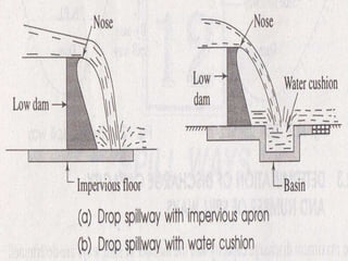
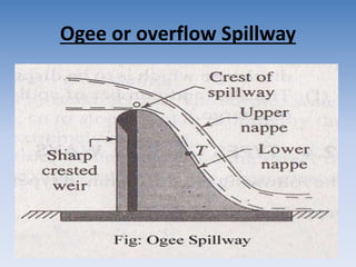
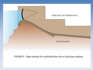
2. SPILLWAYS
• Spillways are provided as integral part of a dam or as an
auxiliary structure constructed separate from the main
dam to release surplus flood water which are in excess of
the storage space in the reservoir as provided in the
operation plan and must be passed downstream.
• The primary function of spillways is to release surplus
waters in conjunction with other discharging devices from
the reservoir, in order to prevent rise of water level above
a specified level in the reservoir to avoid unwanted
submergence upstream or consequent overtopping and
possible failure of the dam. Thus, spillways work as safety
valves for a dam and the adjoining countryside.
• To dissipate this excessive energy and to establish safe
flow conditions in the downstream of a dam spillway,
energy dissipaters are used as remedial devices.
3. Necessity of spillways
• The height of the dam is always fixed according to the
maximum reservoir capacity. The normal pool level
indicates the maximum capacity of the reservoir. The
water is never stored in the reservoir above this level.
The dam may fail by over turning so, for the safety of
the dam the spillways are essential.
• The top of the dam is generally utilized by making road.
The surplus water is not be allowed to over top the
dam, so to stop the over topping by the surplus water,
the spillways become extremely essential.
• To protect the downstream base and floor of the dam
from the effect of scouring and erosion, the spillways
are provided so that the excess water flows smoothly.
4. Location of Spillway
• Spillways may be provided within the body of
the dam.
• Spillways may sometimes be provided at one
side or both sides of the dam.
• Sometimes by-pass spillway is provided which
is completely separate from the dam.
5. Determination of discharge capacity
and number of spillways
• By studying the flood hydrograph of past ten years, the
maximum flood discharge may be computed which is
to be disposed off completely through the spillways.
• The water level in the reservoir should never be
allowed to rise above the maximum pool level and
should remain in normal pool level. So, the volume of
water collected between maximum pool level and
minimum pool level computed, which indicates the
discharge capacity of spillways.
• The maximum flood discharge may also be computed
from other investigation like, rainfall records, flood
routing, empirical flood discharge formulae, etc.
6. Determination of discharge capacity
and number of spillways
• From the above factors the highest flood
discharge is ascertained to fix the discharge
capacity of spillways.
• The natural calamities are beyond the grip of
human being. So, an allowance of about 25 %
should be given to the computed highest
flood discharge which is to be disposed off.
• The size and number of spillways are designed
according to the design discharge.
7. Types of Spillways
• Free over fall or straight drop Spillways
• Ogee or overflow Spillway
• Siphon Spillway
• Side Channel Spillway
• Chute or Trough or Open channel Spillway
• Drop inlet or Shaft or morning glory Spillway
8. Free over fall or straight drop
Spillways
• Water flows over a relatively thin spillway crest
and falls freely to the downstream.
• Usually appropriate for thin dams having almost
vertical downstream faces.
• This type of spillways may be economical for low
heads as compared with overflow spillways
because of saving in concrete.
• Not recommended for high heads because of
structural instability problems.
• A basin is constructed on the downstream side to
form a small artificial pool which is known as
water cushion.
11. Ogee or overflow Spillway
• The ogee spillway is a modified form of drop
spillway.
• Overflow spillways also called ogee-shaped (S-
shaped) spillways.
• This type of spillways allows the passage of
the flood wave over its crest.
• Widely used on Gravity dams, Arch dams, and
Buttress dams
12. Ogee or overflow Spillway
• The flow depth at the crest is slightly critical
than hydrostatic pressure.
Overflow spillways
• Controlled (gated, guided)
• Uncontrolled (ungated, free)
• Almost all recently constructed dams are
installed with crest gates to store more water
in the reservoir.
13. Ogee or overflow Spillway
• The downstream profile of the spillway is
made to coincide with the shape of the lower
nappe of the free falling water jet from a
sharp crested weir.
• The shape of the lower nappe is not same for
all the head of water above the crest of the
weir.
• It differs with the head of water.
• for the design of the ogee spillway the
maximum head is considered.
14. Ogee or overflow Spillway
• If the spillway runs with the maximum head,
then the overflowing water just follows the
curved profile of the spillway and there is no
gap between the water and the spillway
surface and the discharge is maximum.
• When the actual head becomes more than the
designed head, the lower nappe does not
follow the ogee profile and gets separated
from the spillway surface.
15. Ogee or overflow Spillway
• Thus a negative pressure develops at the point of
separation.
• Due to the negative pressure, air bubbles are
formed within the flowing water.
• These air bubbles air responsible for the frictional
force (i.e. abrasion) which causes much damage
to the spillway surface.
• if the head of water is less than the designed
head, the waterjet adheres to the body of the
spillway and creases positive pressure which
reduces the discharge through the spillway.
19. Siphon Spillway
It is designed by the principle of a siphon.
When water rises over the FRL then water start spilling.
There is a air vent for removing the entrapped
pressure from the water.
It is a closed conduit system formed in the shape of an
inverted U-tube, positioned so that the inside of the
bend of the upper passageway is at the normal storage
level of the reservoir.
The initial discharges from the siphon spillway are just
like the discharge over a weir.
After the air in the bend over the crest is exhausted,
the water is discharged through siphonic action.
21. Side Channel Spillway
If a sufficient crest length is not available for an overflow or
chute spillways in narrow valleys, floodwater is taken in a
side channel.
When the dam is not rigid and it is undesirable to pass
flood water over the dam , this type of spillway is used.
After passing crossing over the spillway crest ,water flows
parallel to the crest.
The crest is placed parallel to the discharge channel. Flow
into the side channel might enter on only one side of the
trough in the case of steep hillside locations, or on both
sides and over the end of the trough if it is located on a
knoll or gently sloping abutment.
Discharge characteristics are similar to an ordinary
overflow weir, except that at a high discharge the crest may
be partly submerged.
24. Chute or Trough or Open channel
Spillway
• In this type water is conveyed from the reservoir to the
river or to nalla below the dam through an excavated
open channel, through fairly steep slope.
• In case of having sufficient stiff foundation conditions
at the spillway location, a chute spillway may be used
in stead of overflow spillway due to economic
consideration.
• A steep slope open channel is constructed in slabs with
25-50 cm thickness having lengths of approximately 10
m.
• When the horizontal distance between the upstream of
the spillway and the tail water is considerable long, a
long steep sloped chute usually follows the overflow
spillway until the tail water.
25.
26.
27. Drop inlet or Shaft or morning glory
Spillway
If a sufficient space is not available for an
overflow spillway, a shaft spillway may be
considered.
In the site of shaft spillway
Seismic action should be small,
Stiff geologic formation should be available, and
Possibility of floating debris is relatively small.
Flow conditions in the spillway:
Level 1 - a weir flow
Level 2 -midway between weir flow and pipe flow
Level 3- pressurized pipe flow.
28. Drop inlet or Shaft or morning glory
Spillway
Flow conditions in the spillway:
Level 1- a weir flow
Cs: discharge coefficient for a shaft spillway.
H0: total head on the inlet
R: radius of the shaft inlet
Weir flow with air entrainment takes place until
point A.
Pressurized pipe flow starts after point B.
Part of the curve between point A and B
describes the combination of weir and pipe flows.
30. Drop inlet or Shaft or morning glory
Spillway
• When the shaft is completely submerged, further
increase in head will not result in appreciable
increase in discharge.
• This type of spillway is not suitable for large
capacity and deep reservoirs because of stability
problems.
• Special designs are required to handle cavitations
damage at the transition between shaft and
tunnel.
• Repair and maintenance of shaft spillways are
difficult.
35. Factor affecting selection of spillway
• Safety Considerations Consistent with Economy
• Hydrological and Site Conditions
inflow flood
availability of tail channel, its capacity and flow hydraulics
power house, tail race and other structures downstream
Topography
• Type of Dam
• Purpose of Dam and Operating, Conditions
• Conditions Downstream of a Dam
• Nature and Amount of Solid Materials Brought by the
River
36. Special consideration
Ogee spillway
a) It is most commonly used with gravity dams.
However, it is also used with earth and rockfill
dams with a separate gravity structure;
b) The ogee crest can be used as control in
almost all types of spillways; and
c) It has got the advantage over other spillways
for its high discharging efficiency.
37. Special consideration
Chute Spillway
a) It can be provided on any type of foundation,
b) It is commonly used with the earth and rockfill dams,
and
c) It becomes economical if earth received from spillway
excavation is used in dam construction.
Following factors limit its adaption:
a) It should normally be avoided on embankment;
b) Availability of space is essential for keeping the
spillway basins away from the dam paving; and
c) If it is necessary to provide too many bend, in the chute
because of the topography, its hydraulic performance
can be adversely affected.
38. Special consideration
Site Chanel Spillway
a) This type of spillway is preferred where a long
overflow crest is desired in order to limit the
intensity of discharge,
b) It is useful where the abutments are steep, and
c) It is useful where the control is desired by the
narrow side channel.
Note: - The factor limiting its adoption is that this
type of spillway is hydraulically less efficient.
39. Special consideration
Shaft Spillway (Morning Glory Spillway)
a) This can be adopted very advantageously in dam sites
in narrow canyons, and
b) Minimum discharging capacity is attained at relatively
low heads. This characteristic makes the spillway ideal
where the maximum spillway outflow is to be limited.
This characteristic become undesirable where a flood
more than the design capacity is to be passed. So, it
can be used as a service spillway in conjunction with an
emergency spillway.
Note: - The factor limiting its adoption is the difficulty of
air-entrainment in a shaft, which may escape in bursts
causing an undesirable surging motion.
40. Special consideration
Siphon Spillway
a) Siphon spillways can be used to discharge full capacity discharges, at relatively
low heads, and
b) Great advantage of this type of spillway is its positive and automatic operation
without mechanical devices and moving parts.
The following factors limit the adoption of a siphon spillway:
a) It is difficult to handle flows materially greater than designed capacity, even if
the reservoir head exceeds the design level;
b) Siphon spillways cannot pass debris, ice, etc;
c) There is possibility of clogging of the siphon passage way and breaking of
siphon vents with logs and debris;
d) In cold climates, there can be freezing inside the inlet and air vents of the
siphon;
e) When sudden surges occur and outflow stops;
f) The structure is subject to heavy vibrations during its operation needing strong
foundations; and
g) Siphons cannot be normally used for vacuum heads higher than 8 m and there
is danger of cavitation damage.
41. Special consideration
Over fall or Free Fall Spillway
a)This is suitable for arch dams or dams with
downstream vertical faces; and
b) This is suitable for small drops and for passing
any occasional flood.
Note: -The factor limiting its adoption is that,
ordinarily, the maximum hydraulic drop from
head pool to tail pool water should not exceed
20 m,
42. ENERGY DISSIPIATORS
• Hydraulic structures constructed at the D/S
end of a dam to dissipate the huge K.E. of
water
• Due to this provision large scale scour near
the toe of dam can be prevented.
43. • In general, K.E. of this supercritical flow can
dissipated by
A. By converting the supercritical flow by hydraullic
jump to sub critical flow, i.e. provision of Stilling
Basin.
B. By directing the flow of water in the air and then
making it fall away from toe of the Dam, i.e.
provision of Bucket type energy Dissipators.
44. Stilling Basin Type Energy Dissipators
They may fundamentally be divided into two types:
1. Horizontal apron type
2. Sloping apron type
45.
46.
47. Bucket type energy dissipators can be either:
a) Roller bucket type energy dissipator; or
b) Trajectory bucket type energy dissipator.
The following two types of roller buckets are
adopted on the basis of tailwater conditions and
importance of the structure:
• a) Solid roller bucket, and
• b) Slotted roller bucket
48.
49.
50.
51. SELECTION Of An ENERGY DISSIPATOR
• An energy dissipator is selected based upon
the following 2 parameters
1. Jump Height: which is fixed for a discharge
intensity and height of a spillway.
2. Tail Water Depth: which is calculated by
actual discharge observations.
52. • Now a Graph is plotted between:
1. Jump Heights (depths) v/s Discharge.
2. Tail Water Depth v/s Discharge.
The above Graphs are superimposed and
following cases are analysed:
54. • This is the ideal case
• In this, the horizontal apron provided on the
riverbed downstream from the toe of the
spillway would suffice.
• The length of the apron should be equal to the
length of the jump corresponding to the
maximum discharge over the spillway.
57. • It is apparent that the tail water depth as
provided by the natural river is not sufficiently
for the jump to form.
• This may be over come by providing:
a stilling basin apron that is depressed below
the average riverbed level, or
a sill or baffle of sufficient height at the end
of the spillway, or
A ski jump, i.e. Trajectory roller bucket.
60. • Since this situation results in submergence of
the jump,
• Therefore, it is necessary to raise the floor in
order to form a clear jump.
• In practice, it is done by providing AN
INCLINED APRON OF THE STILLING BASIN or
A ROLLER BUCKET
63. • This situation may be taken care of by
providing an inclined floor in the upper
portion of the stilling basin and
• providing either a depressed floor in the lower
portion of the basin or provide a baffle at the
end of the basin.
65. • In this case a sloping apron may be provided
which lies partly above and partly below the
riverbed.
• So that the jump will form on the higher slope
at low discharges and on the lower slope at
high discharges
66. RTU Questions
• What are the essential requirements of a spillway?
Describe the process of determining spillway capacity?
• Describe various types of spillways with sketches?
• Describe and sketch ogee shaped spillways with equations
of its downstream and upstream.
• Describe the factor affecting the required spillway capacity.
What is the role of flood routing in spillways design?
• Enumerate the various types of spillways. Describe the
Chute spillway with a neat sketch? Also describe the design
of its various component.
67. References
• Irrigation Engineering & Water Power Engineering
– By Prof. P.N.MODI and Dr. S.M. SETH
--- Standard Book House Delhi
• Irrigation Engineering & Hydraulic Structures
– By Prof. Santosh Kumar Garg
– Khanna Publishers
• Irrigation, Water Power Engineering & Hydraulic Structures
– By Prof K.R. Arora
– Standard Publishers Distributions
• Internet Websites
• http://www.aboutcivil.org/
• http://nptel.ac.in/courses/105105110/