Downloaded 532 times
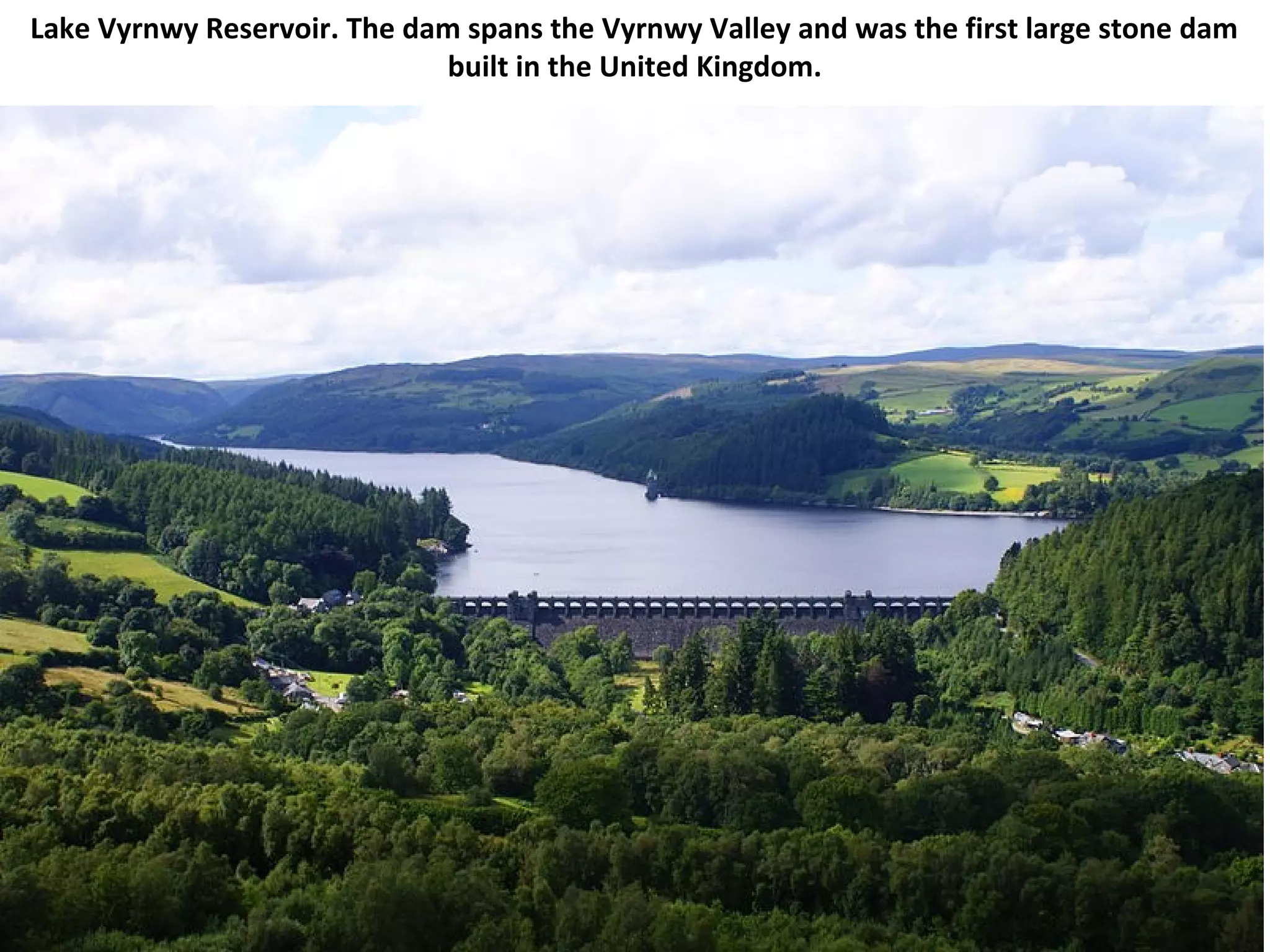

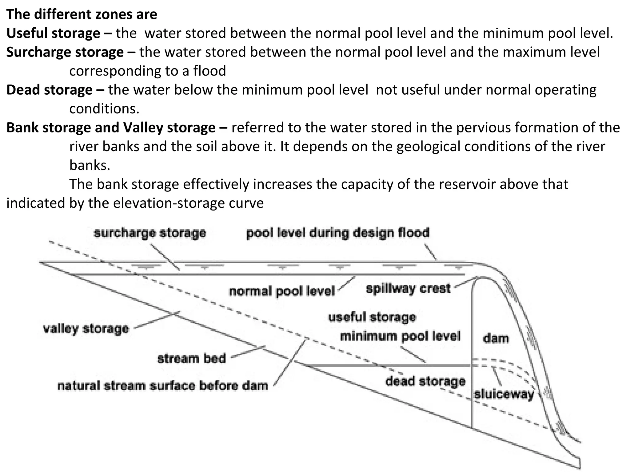
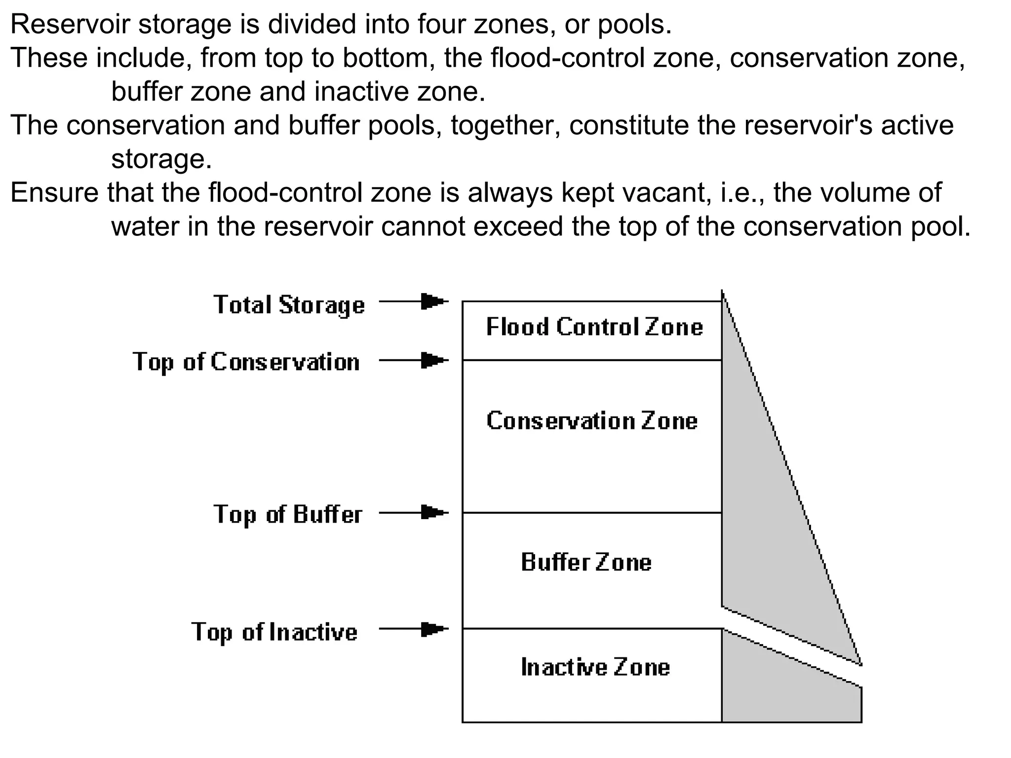
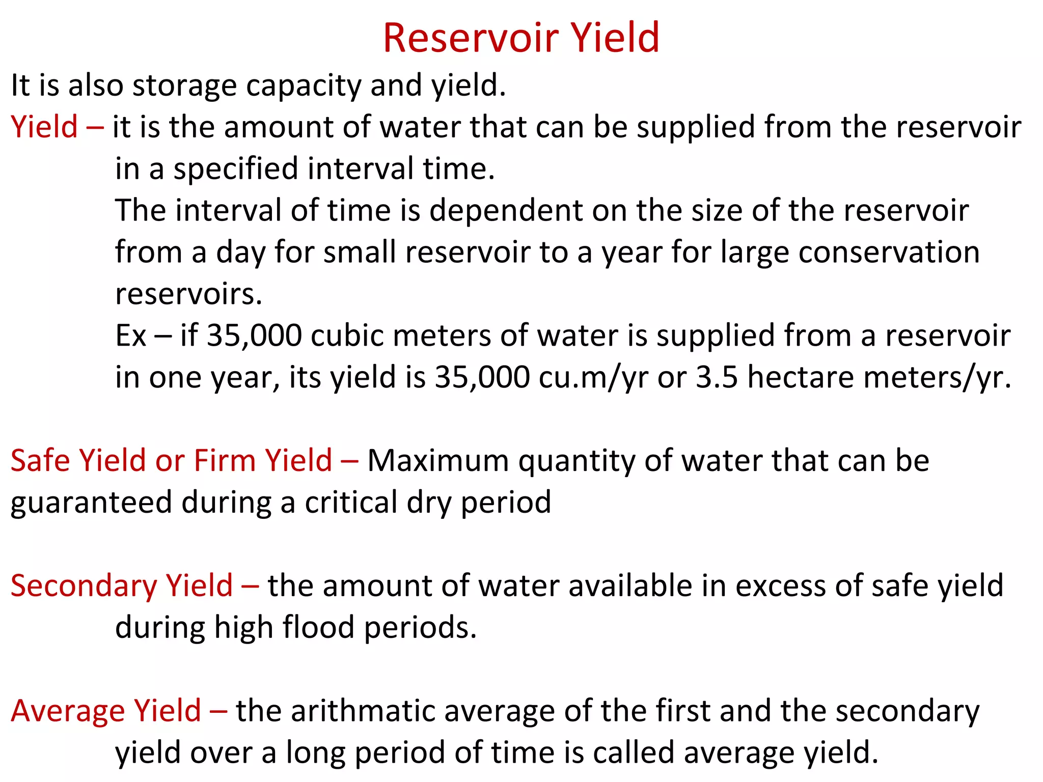
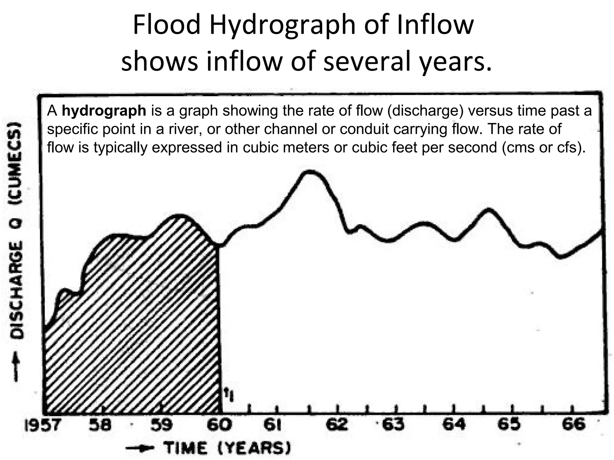

Reservoirs are artificial lakes or dams used to store water. They are created through dam construction in river valleys or excavation. Reservoirs store water for uses like irrigation, drinking water, hydroelectric power, and flood control. The storage capacity and zones of a reservoir, including dead storage, conservation, and flood control zones, determine how much water can be supplied over time periods ranging from daily to yearly. Hydrological investigations study runoff patterns and flood risks to inform reservoir planning and design.


