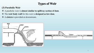
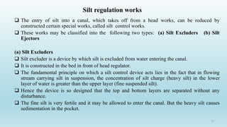
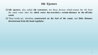
06. Diversion Headworks-2
B.Sc. Civil Engineering 8th Semester
Muhammad Ajmal (PhD)
Lecturer
Agri. Engg. Deptt.
CE-402 Irrigation Engineering
1
Site Selection for Diversion Headworks
 The following points should be considered to select a site for this diversion headworks.
 The river should be straight and narrow at the site
 The elevation of site should be higher than the area to be irrigated for gravity flow.
 River banks at site should be well defined and stable.
 There should be suitable arrangement for the diversion of river during construction.
 Valuable land upstream of the barrier like weir or barrage should not be submerged.
 Material of construction should be locally available.
2
Site Selection for Diversion Headworks
 Roads or railway communication to the site is essential to carry the material of
construction.
 Site should be close to the cropland to minimize loss of water due to seepage and
evaporation of canal.
 The site should provide a good foundation for construction of weir or barrage.
 The site should be such that the weir (or barrage) can be aligned at right angles to the
direction of flow in the river.
 The overall cost of the project should be a minimum.
3
Selection of Site for Diversion Headworks
4
Comparison Between Weir & a Barrage
Barrage Weir
Low set crest High set crest
Ponding is done by means of gates Ponding is done against the raised
crest or partly against crest and partly
by shutters
Gated over entire length Shutters in part length
Gates are of greater height Shutters are of smaller height, 2 m
Perfect control on river flow No control of river in low floods
High floods can be passed with
minimum afflux
Excessive afflux in high floods
Less silting upstream due to low set
crest
Raised crest causes silting upstream
Longer construction period Shorter construction period
Silt removal is done through under
sluices
No means for silt disposal
Costly structure Relatively cheaper structure
5
Afflux Conceptual Sketch
Afflux: The rise in water level (above normal) on the upstream side of a bridge or obstruction (weir
or barrage) caused when the effective flow area at the obstruction is less than the natural width of
the stream immediately upstream of the obstruction.
6
Types of Weir
 The type of weir in which the uplift pressure due to seepage of water below the floor is resisted
entirely by the weight of the floor is gravity weir.
 In case of non gravity weir the floor thickness is kept less and the uplift pressure is largely
resisted by reinforced concrete floor.
 Weir may be of different types based on material of construction, design features and types of
soil foundation as: (1) Vertical drop weir (2) Sloping weir (3) Parabolic weir
7
Types of Weir
(1) Vertical Drop Weir
 This type of weir consists of a vertical drop
wall or crest wall, with or without crest
shutter.
 At the upstream and downstream ends of
impervious floor cutoff piles are provided.
 Launching apron are provided both at
upstream and downstream ends of floor to
safeguard against scouring action.
 A graded filter is provided immediately at
the downstream end of impervious floor to
relieve the uplift pressure.
 This type of weir is suitable for any type of
foundation.
8
Vertical Drop Weir
9
Types of Weir
(2-1) Masonry or Concrete Sloping Weir
 This type is suitable for soft sandy
foundation.
 It is used where difference in weir crest
and downstream riverbed is not more
than 3 m.
 Hydraulic jump is formed when water
passes over the sloping glacis.
 Weir of this type is of recent origin.
10
(2-2) Dry Stone Slopping Weir
 It is dry stone or rock filled weir.
 It consists of a body wall (or weir wall)
and upstream and downstream dry stones
are laid in the form of glacis (up and down
sloping surface) with some intervening
core wall.
Types of Weir
11
Types of Weir
(3) Parabolic Weir
 A parabolic weir is almost similar to spillway section of dam.
 The weir body wall for this weir is designed as low dam.
 A cistern is provided at downstream.
12
Barrage
• When the water level on the upstream side of the weir is required to be raised to
different levels at different time, then the barrage is constructed.
• Practically a barrage is an arrangement of adjustable gates or shutters at different
tiers over the weir.
• The water level can be adjusted by the opening of gates.
13
Location of Headworks
 A river, in its course is divided into four distinct regions or stages. Construction of a head work in
these area having the following advantages and disadvantages
(i). The torrential, rocky or mountainous stage: The river in this stage has very steep slope and
high velocity.
 Advantages:
 Proper rocky foundation is available so construction cost is less.
 High head is available for hydroelectric work and silt free water for turbine.
 Due to high velocity silt will not be deposited.
 Disadvantage:
 The soil for irrigation must have sufficient depth while in rocky area depth is min.
 Due to high gradient, the canal has to be lined or a number of structures should be constructed.
 Having more stones and shingles, a regulator is required to remove it, increases the cost of
regulator.
 The high velocity in rocky stage requires use of good construction materials, increasing the cost
of construction.
14
Location of Headworks
(ii). The sub-mountainous or boulder stage: The sides and bed of river are composed of
boulder and gravel. There is strong subsoil flow in this region.
 Advantages:
 Cash crop can be grown well.
 Cost of headworks is less due to availability of local materials.
 Less river training work required.
 Falls can be utilized for power generation
 Disadvantages:
 Strong subsoil flow, which decreases the storage and may cause damage to the floor
downstream.
 As in rocky stage, long idle canal length is required.
 More percolation losses due to loses sub soil, so increase the cost per cumec.
 More cross-drainage works/structures are required.
15
Location of Headworks
(iii). Trough stage or alluvial plain: The cross-section of the river is made of alluvial sand and
silt. The bed slopes are small and velocities are gentle.
 Advantages:
 Subsoil flow is comparatively less.
 The head works constructed in this region serve large area than a weir in boulder
 Disadvantages:
 High construction cost
 More river training works
 Silt problem in the canal
(iv) Delta Stage: This stage is not suitable for headworks. Here the width is maximum. Cost
will be maximum and minimum area is to be irrigated.
The first stage and last stage of a river is usually not fit for canal head works.
16
Divide Wall
17
Divide Wall
 The Divide Wall is a long wall constructed at right angle to the weir or barrage.
 It may be constructed with stone masonry or cement concrete.
 On the upstream side, the wall is extended just to cover the canal regulator and on the
downstream side, it is extended up to the launching apron.
 The functions of the divide wall are as follows:
(a) To form a still water pocket in front of the canal head so that the suspended silt can be
settled down which then later can be cleared through the scouring sluices from time to time.
(b) To serve as a side-wall of the fish ladder.
(c) To separate canal head regulator from main weir.
(d) It provides a straight approach in front of the canal head.
(e) It resists the overturning effect on the weir or barrage caused by the pressure of the
impounding water.
18
Under Sluices
19
Scouring Sluices or Under Sluices
 The Scouring sluices are the openings provided at the base of the weir or barrage.
 These openings are provided with adjustable gates.
 Normally, the gates are kept closed.
 The suspended silt goes on the depositing in front of the canal head regulator.
 When the silt deposition becomes appreciable the gates are opened and the deposited silt is
loosened with an agitator mounting on a boat.
 The muddy water flows towards the downstream side through the scouring sluices.
 The gates are closed, but, at the period of flood, the gates are kept opened.
20
Fish Ladder
21
Fish Ladder
22
 The Fish Ladder is provided just by the side of the divide wall for the movement of fishes.
 Rivers are important source of fishes. There are various types of fish in the river. The nature of
fish varies from type to type.
 In general, the tendency of fish is to move from upstream to downstream in winters and from
downstream to upstream in monsoons. This movement is essential for their survival.
 Due to construction of weir or barrage, this movement gets obstructed, and is detrimental to the
fishes.
 For the movement of the fishes along the course of the river, the fish ladder is essential.
 In the fish ladder, the baffle walls are constructed in the zigzag manner so that the velocities of
flow within the ladder does not exceed 3 m/s (mostly 2 to 2.5 m/s).
 The width, length, and height of the fish ladder depends on the nature of the river and the type of
the weir or barrage.
23
Fish Ladder
Fish Ladder
24
Canal Head Regulator
25
Canal Head Regulator
 A structure which is constructed at the head of the canal regulator to regulate the flow of
water is known as canal head regulator.
 It consists of a number of piers which divide the total width of the canal into a number of
spans which are known as bays.
 The pier consists of a number of tiers on which the adjustable gates are placed.
 The gates are operated from the top by suitable mechanical device.
 A platform is produced on the top of the piers for the facility of operating the gates.
 Again some piers are constructed on the downstream side of the canal head to support the
roadway.
26
 The entry of silt into a canal, which takes off from a head works, can be reduced by
constructed certain special works, called silt control works.
 These works may be classified into the following two types: (a) Silt Excluders (b) Silt
Ejectors
(a) Silt Excluders
 Silt excluder is a device by which silt is excluded from water entering the canal.
 It is constructed in the bed in front of head regulator.
 The fundamental principle on which a silt control device acts lies in the fact that in flowing
stream carrying silt in suspension, the concentration of silt charge (heavy silt) in the lower
layer of water is greater than the upper layer (fine suspended silt).
 Hence the device is so designed that the top and bottom layers are separated without any
disturbance.
 The fine silt is very fertile and it may be allowed to enter the canal. But the heavy silt causes
sedimentation in the pocket.
27
Silt regulation works
 To eliminate the suspended heavy silt, the silt excluder is provided. It consists of a series of tunnels
starting from the side of the head regulator up to the divide wall.
 The tunnel nearest to the head regulator is longest, and the successive tunnels decrease in length,
the tunnel nearest to the divide wall is shortest.
 The tunnels are covered by R.C.C. Slab. The top level of the slab is kept below the sill level of the
head regulator.
 The completely clear water is allowed to flow in the canal through the head regulator.
 The suspended heavy silt carried by the water enters the silt excluder tunnels and passes out
through the scouring sluices.
 The clearer water enters the head regulator and silted water enters the silt excluder.
 In this type of works, the silt is, therefore, removed from the water before in enters the canal.
28
Silt regulation works
Silt Excluder
29
Silt Ejectors
 Silt ejectors, also called silt extractors, are those devices which extract the silt from
the canal water after the silted water has traveled a certain distance in the off-take
canal.
 These works are, therefore, constructed on the bed of the canal, and little distance
downstream from the head regulator.
30
Silt Ejectors
31
32

06. Diversion Headworks-2.pdf

  • 1.
    06. Diversion Headworks-2 B.Sc.Civil Engineering 8th Semester Muhammad Ajmal (PhD) Lecturer Agri. Engg. Deptt. CE-402 Irrigation Engineering 1
  • 2.
    Site Selection forDiversion Headworks  The following points should be considered to select a site for this diversion headworks.  The river should be straight and narrow at the site  The elevation of site should be higher than the area to be irrigated for gravity flow.  River banks at site should be well defined and stable.  There should be suitable arrangement for the diversion of river during construction.  Valuable land upstream of the barrier like weir or barrage should not be submerged.  Material of construction should be locally available. 2
  • 3.
    Site Selection forDiversion Headworks  Roads or railway communication to the site is essential to carry the material of construction.  Site should be close to the cropland to minimize loss of water due to seepage and evaporation of canal.  The site should provide a good foundation for construction of weir or barrage.  The site should be such that the weir (or barrage) can be aligned at right angles to the direction of flow in the river.  The overall cost of the project should be a minimum. 3
  • 4.
    Selection of Sitefor Diversion Headworks 4
  • 5.
    Comparison Between Weir& a Barrage Barrage Weir Low set crest High set crest Ponding is done by means of gates Ponding is done against the raised crest or partly against crest and partly by shutters Gated over entire length Shutters in part length Gates are of greater height Shutters are of smaller height, 2 m Perfect control on river flow No control of river in low floods High floods can be passed with minimum afflux Excessive afflux in high floods Less silting upstream due to low set crest Raised crest causes silting upstream Longer construction period Shorter construction period Silt removal is done through under sluices No means for silt disposal Costly structure Relatively cheaper structure 5
  • 6.
    Afflux Conceptual Sketch Afflux:The rise in water level (above normal) on the upstream side of a bridge or obstruction (weir or barrage) caused when the effective flow area at the obstruction is less than the natural width of the stream immediately upstream of the obstruction. 6
  • 7.
    Types of Weir The type of weir in which the uplift pressure due to seepage of water below the floor is resisted entirely by the weight of the floor is gravity weir.  In case of non gravity weir the floor thickness is kept less and the uplift pressure is largely resisted by reinforced concrete floor.  Weir may be of different types based on material of construction, design features and types of soil foundation as: (1) Vertical drop weir (2) Sloping weir (3) Parabolic weir 7
  • 8.
    Types of Weir (1)Vertical Drop Weir  This type of weir consists of a vertical drop wall or crest wall, with or without crest shutter.  At the upstream and downstream ends of impervious floor cutoff piles are provided.  Launching apron are provided both at upstream and downstream ends of floor to safeguard against scouring action.  A graded filter is provided immediately at the downstream end of impervious floor to relieve the uplift pressure.  This type of weir is suitable for any type of foundation. 8
  • 9.
  • 10.
    Types of Weir (2-1)Masonry or Concrete Sloping Weir  This type is suitable for soft sandy foundation.  It is used where difference in weir crest and downstream riverbed is not more than 3 m.  Hydraulic jump is formed when water passes over the sloping glacis.  Weir of this type is of recent origin. 10
  • 11.
    (2-2) Dry StoneSlopping Weir  It is dry stone or rock filled weir.  It consists of a body wall (or weir wall) and upstream and downstream dry stones are laid in the form of glacis (up and down sloping surface) with some intervening core wall. Types of Weir 11
  • 12.
    Types of Weir (3)Parabolic Weir  A parabolic weir is almost similar to spillway section of dam.  The weir body wall for this weir is designed as low dam.  A cistern is provided at downstream. 12
  • 13.
    Barrage • When thewater level on the upstream side of the weir is required to be raised to different levels at different time, then the barrage is constructed. • Practically a barrage is an arrangement of adjustable gates or shutters at different tiers over the weir. • The water level can be adjusted by the opening of gates. 13
  • 14.
    Location of Headworks A river, in its course is divided into four distinct regions or stages. Construction of a head work in these area having the following advantages and disadvantages (i). The torrential, rocky or mountainous stage: The river in this stage has very steep slope and high velocity.  Advantages:  Proper rocky foundation is available so construction cost is less.  High head is available for hydroelectric work and silt free water for turbine.  Due to high velocity silt will not be deposited.  Disadvantage:  The soil for irrigation must have sufficient depth while in rocky area depth is min.  Due to high gradient, the canal has to be lined or a number of structures should be constructed.  Having more stones and shingles, a regulator is required to remove it, increases the cost of regulator.  The high velocity in rocky stage requires use of good construction materials, increasing the cost of construction. 14
  • 15.
    Location of Headworks (ii).The sub-mountainous or boulder stage: The sides and bed of river are composed of boulder and gravel. There is strong subsoil flow in this region.  Advantages:  Cash crop can be grown well.  Cost of headworks is less due to availability of local materials.  Less river training work required.  Falls can be utilized for power generation  Disadvantages:  Strong subsoil flow, which decreases the storage and may cause damage to the floor downstream.  As in rocky stage, long idle canal length is required.  More percolation losses due to loses sub soil, so increase the cost per cumec.  More cross-drainage works/structures are required. 15
  • 16.
    Location of Headworks (iii).Trough stage or alluvial plain: The cross-section of the river is made of alluvial sand and silt. The bed slopes are small and velocities are gentle.  Advantages:  Subsoil flow is comparatively less.  The head works constructed in this region serve large area than a weir in boulder  Disadvantages:  High construction cost  More river training works  Silt problem in the canal (iv) Delta Stage: This stage is not suitable for headworks. Here the width is maximum. Cost will be maximum and minimum area is to be irrigated. The first stage and last stage of a river is usually not fit for canal head works. 16
  • 17.
  • 18.
    Divide Wall  TheDivide Wall is a long wall constructed at right angle to the weir or barrage.  It may be constructed with stone masonry or cement concrete.  On the upstream side, the wall is extended just to cover the canal regulator and on the downstream side, it is extended up to the launching apron.  The functions of the divide wall are as follows: (a) To form a still water pocket in front of the canal head so that the suspended silt can be settled down which then later can be cleared through the scouring sluices from time to time. (b) To serve as a side-wall of the fish ladder. (c) To separate canal head regulator from main weir. (d) It provides a straight approach in front of the canal head. (e) It resists the overturning effect on the weir or barrage caused by the pressure of the impounding water. 18
  • 19.
  • 20.
    Scouring Sluices orUnder Sluices  The Scouring sluices are the openings provided at the base of the weir or barrage.  These openings are provided with adjustable gates.  Normally, the gates are kept closed.  The suspended silt goes on the depositing in front of the canal head regulator.  When the silt deposition becomes appreciable the gates are opened and the deposited silt is loosened with an agitator mounting on a boat.  The muddy water flows towards the downstream side through the scouring sluices.  The gates are closed, but, at the period of flood, the gates are kept opened. 20
  • 21.
  • 22.
  • 23.
     The FishLadder is provided just by the side of the divide wall for the movement of fishes.  Rivers are important source of fishes. There are various types of fish in the river. The nature of fish varies from type to type.  In general, the tendency of fish is to move from upstream to downstream in winters and from downstream to upstream in monsoons. This movement is essential for their survival.  Due to construction of weir or barrage, this movement gets obstructed, and is detrimental to the fishes.  For the movement of the fishes along the course of the river, the fish ladder is essential.  In the fish ladder, the baffle walls are constructed in the zigzag manner so that the velocities of flow within the ladder does not exceed 3 m/s (mostly 2 to 2.5 m/s).  The width, length, and height of the fish ladder depends on the nature of the river and the type of the weir or barrage. 23 Fish Ladder
  • 24.
  • 25.
  • 26.
    Canal Head Regulator A structure which is constructed at the head of the canal regulator to regulate the flow of water is known as canal head regulator.  It consists of a number of piers which divide the total width of the canal into a number of spans which are known as bays.  The pier consists of a number of tiers on which the adjustable gates are placed.  The gates are operated from the top by suitable mechanical device.  A platform is produced on the top of the piers for the facility of operating the gates.  Again some piers are constructed on the downstream side of the canal head to support the roadway. 26
  • 27.
     The entryof silt into a canal, which takes off from a head works, can be reduced by constructed certain special works, called silt control works.  These works may be classified into the following two types: (a) Silt Excluders (b) Silt Ejectors (a) Silt Excluders  Silt excluder is a device by which silt is excluded from water entering the canal.  It is constructed in the bed in front of head regulator.  The fundamental principle on which a silt control device acts lies in the fact that in flowing stream carrying silt in suspension, the concentration of silt charge (heavy silt) in the lower layer of water is greater than the upper layer (fine suspended silt).  Hence the device is so designed that the top and bottom layers are separated without any disturbance.  The fine silt is very fertile and it may be allowed to enter the canal. But the heavy silt causes sedimentation in the pocket. 27 Silt regulation works
  • 28.
     To eliminatethe suspended heavy silt, the silt excluder is provided. It consists of a series of tunnels starting from the side of the head regulator up to the divide wall.  The tunnel nearest to the head regulator is longest, and the successive tunnels decrease in length, the tunnel nearest to the divide wall is shortest.  The tunnels are covered by R.C.C. Slab. The top level of the slab is kept below the sill level of the head regulator.  The completely clear water is allowed to flow in the canal through the head regulator.  The suspended heavy silt carried by the water enters the silt excluder tunnels and passes out through the scouring sluices.  The clearer water enters the head regulator and silted water enters the silt excluder.  In this type of works, the silt is, therefore, removed from the water before in enters the canal. 28 Silt regulation works
  • 29.
  • 30.
    Silt Ejectors  Siltejectors, also called silt extractors, are those devices which extract the silt from the canal water after the silted water has traveled a certain distance in the off-take canal.  These works are, therefore, constructed on the bed of the canal, and little distance downstream from the head regulator. 30
  • 31.
  • 32.