Downloaded 51 times

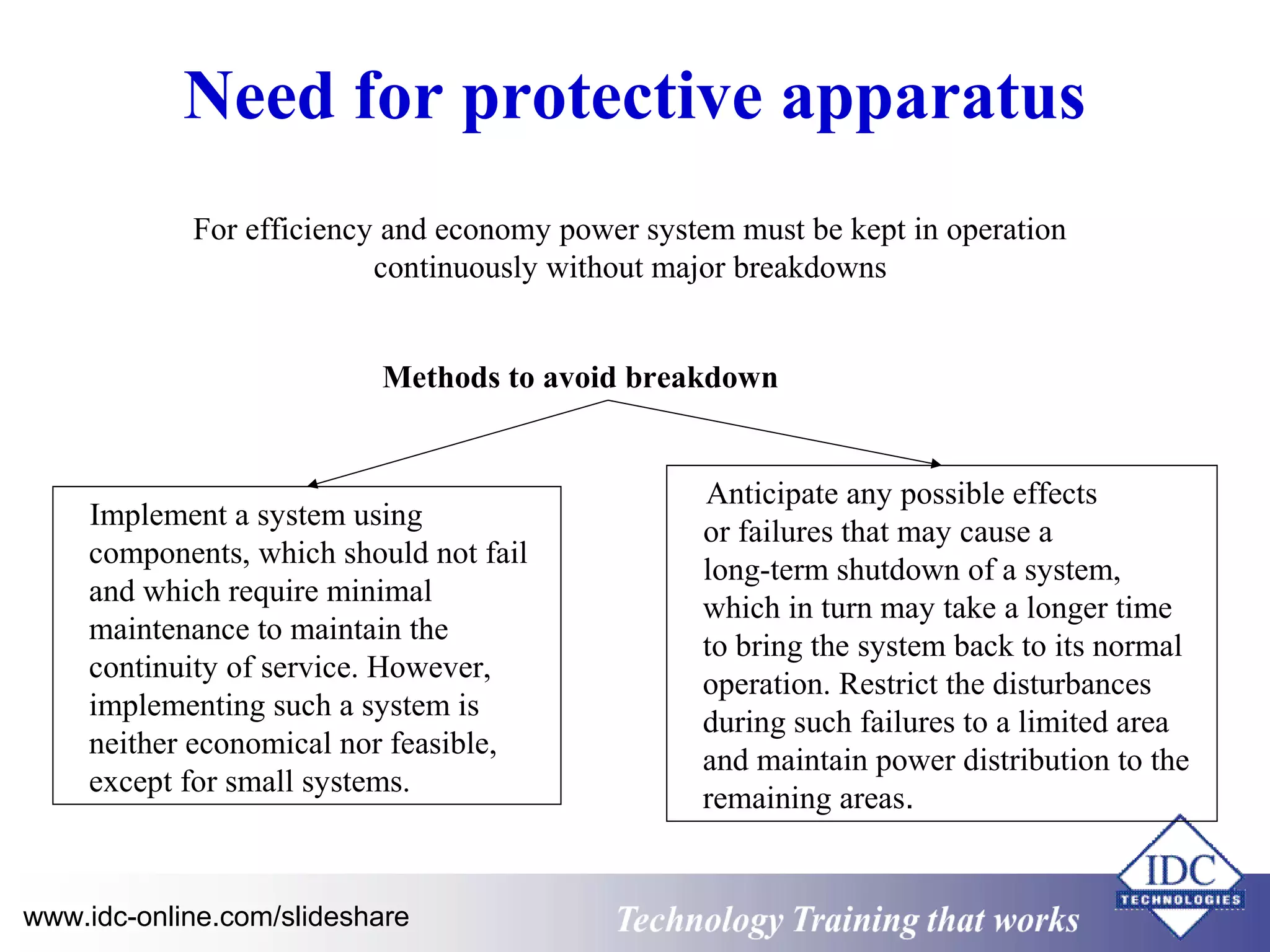
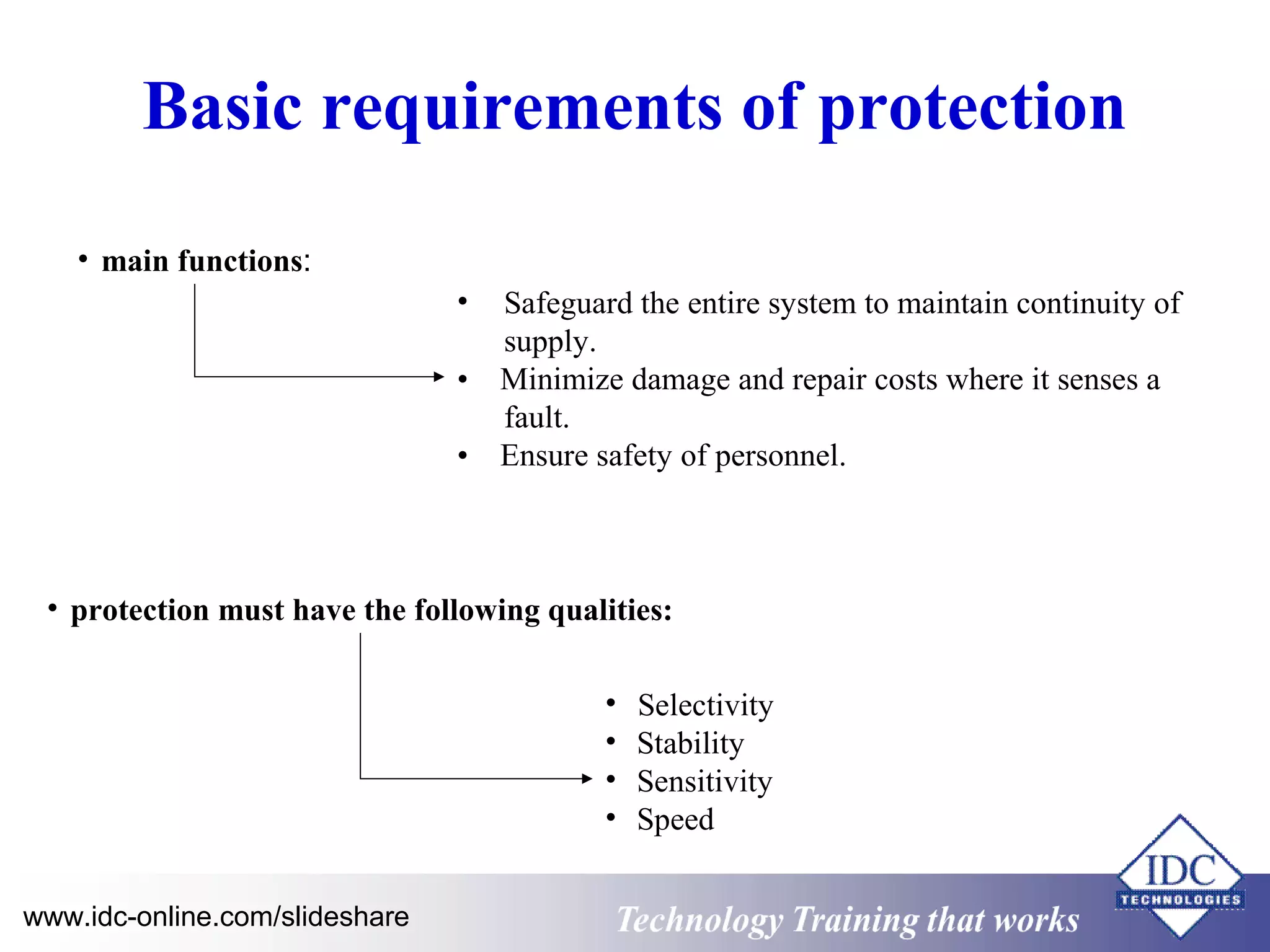
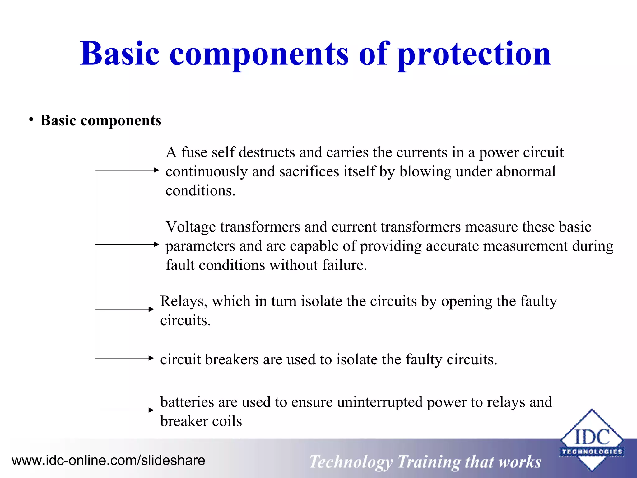
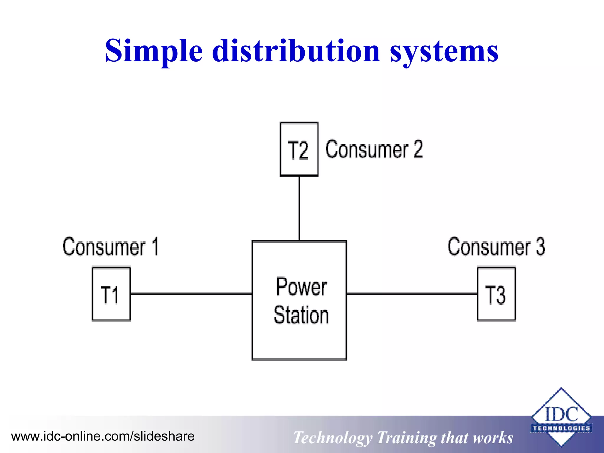
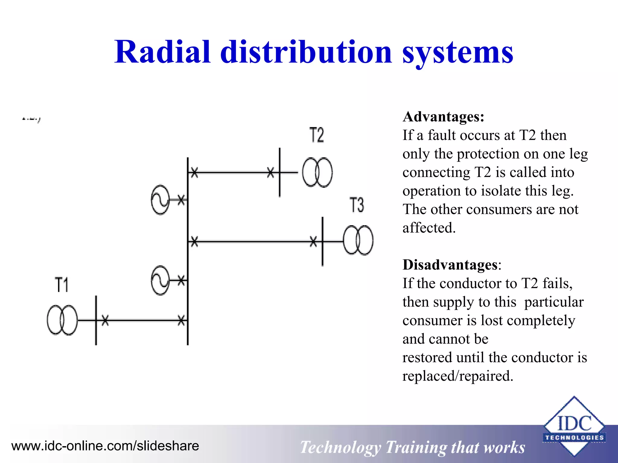
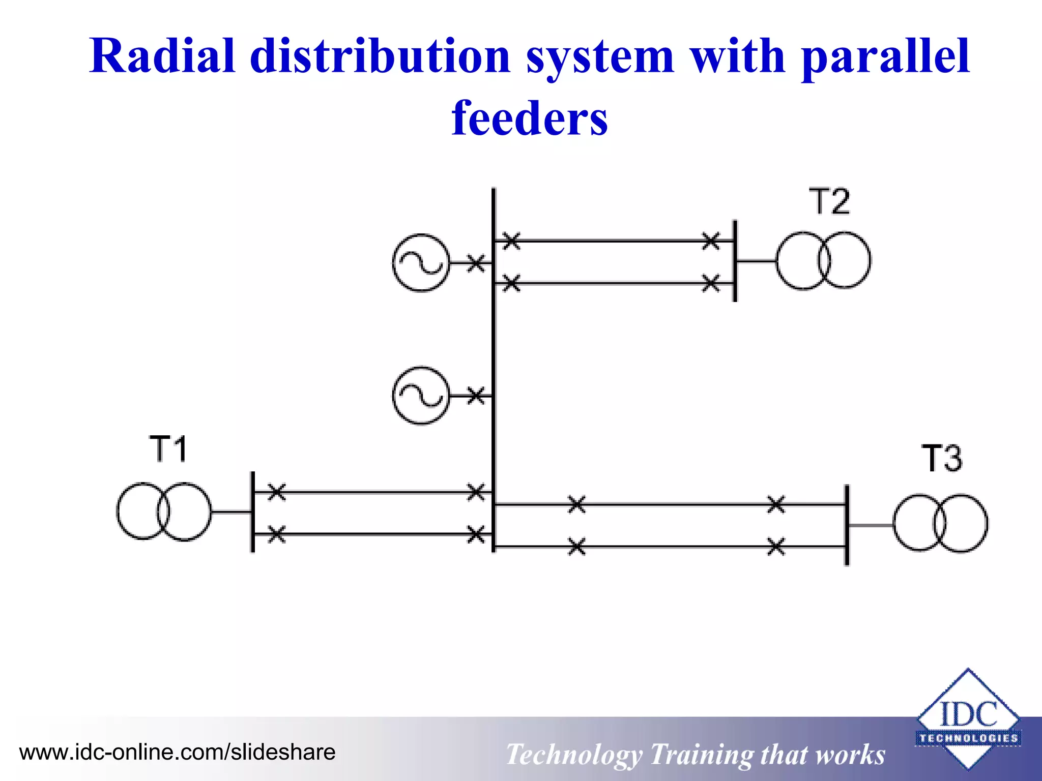
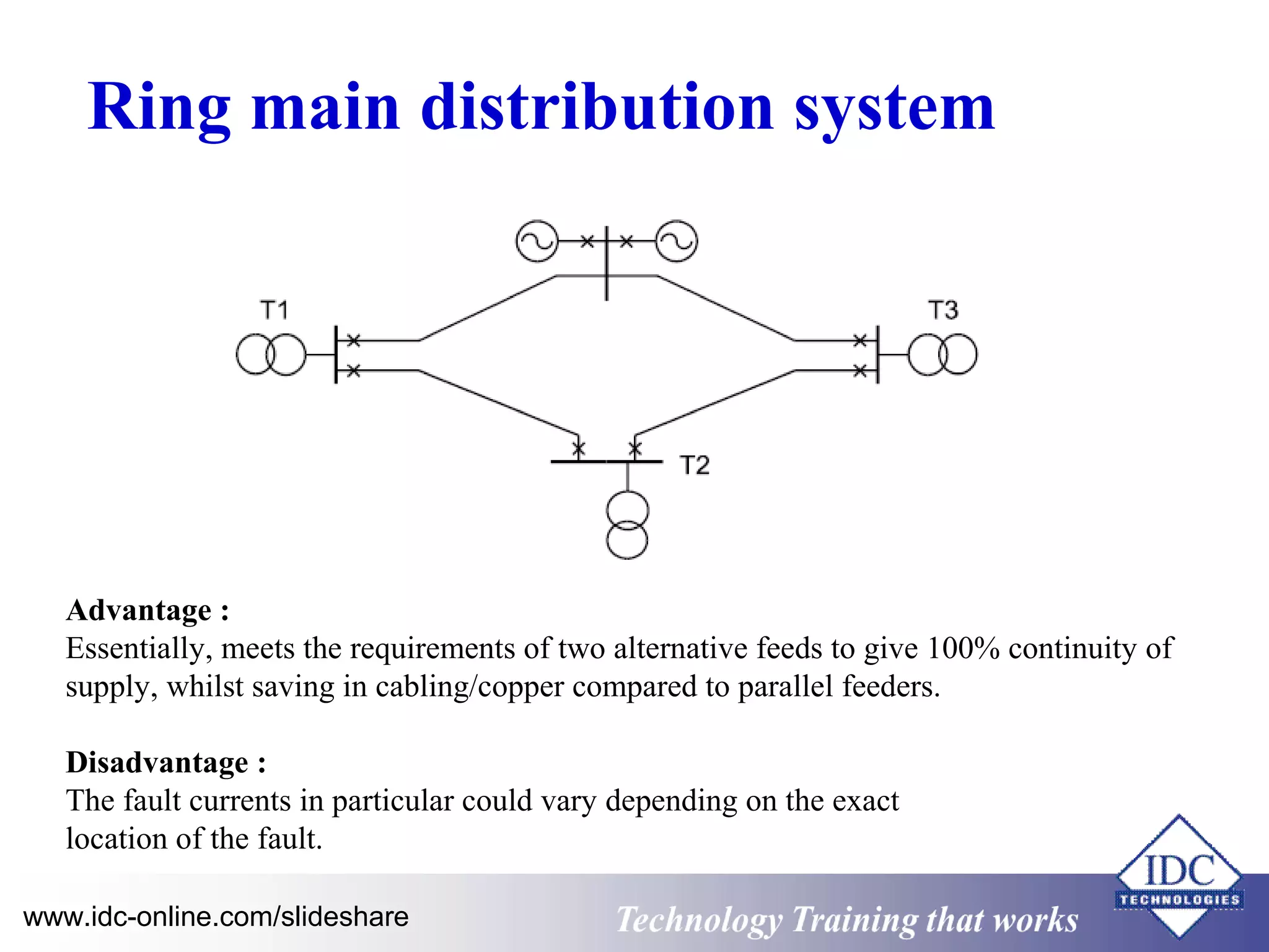
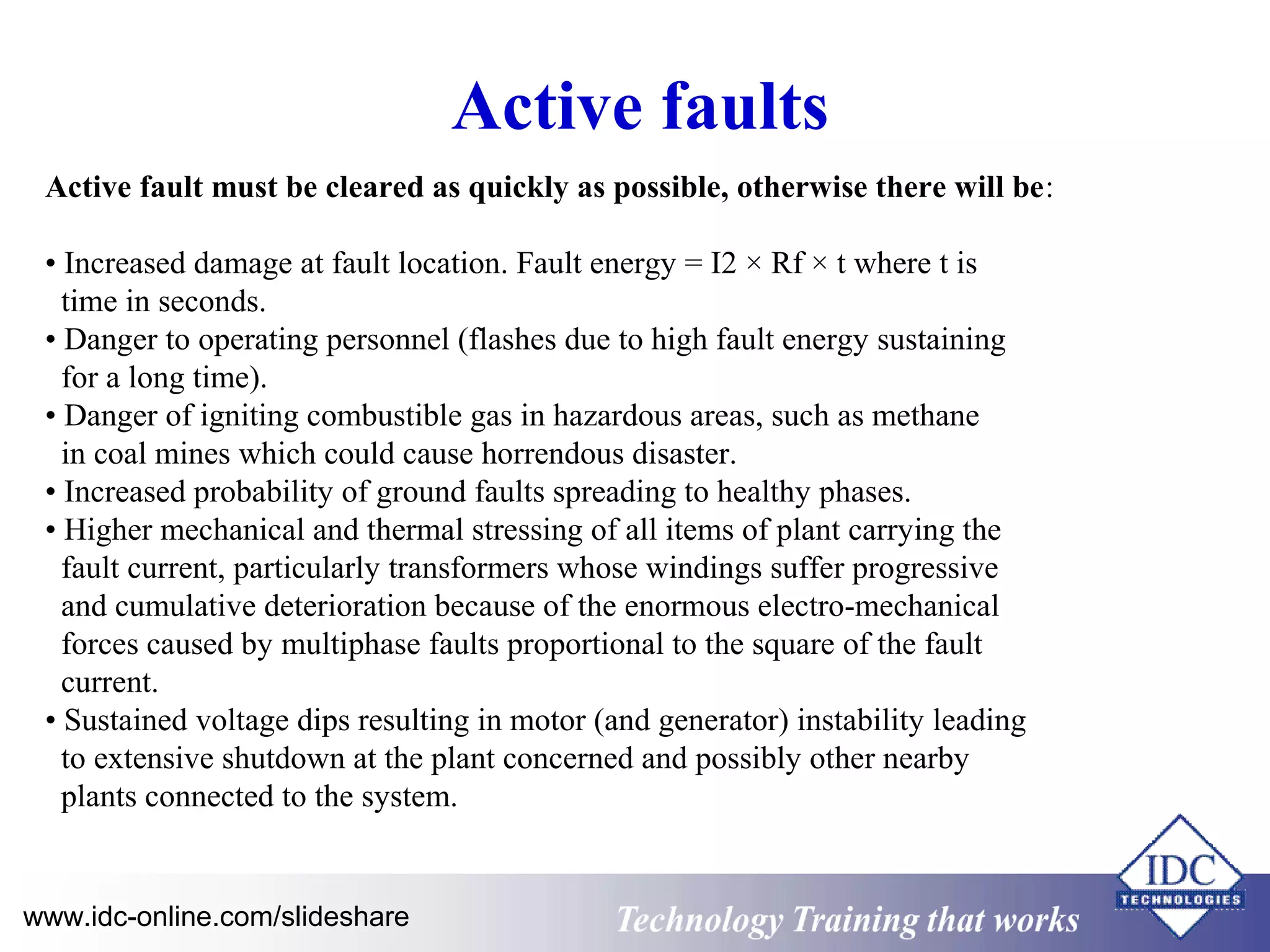
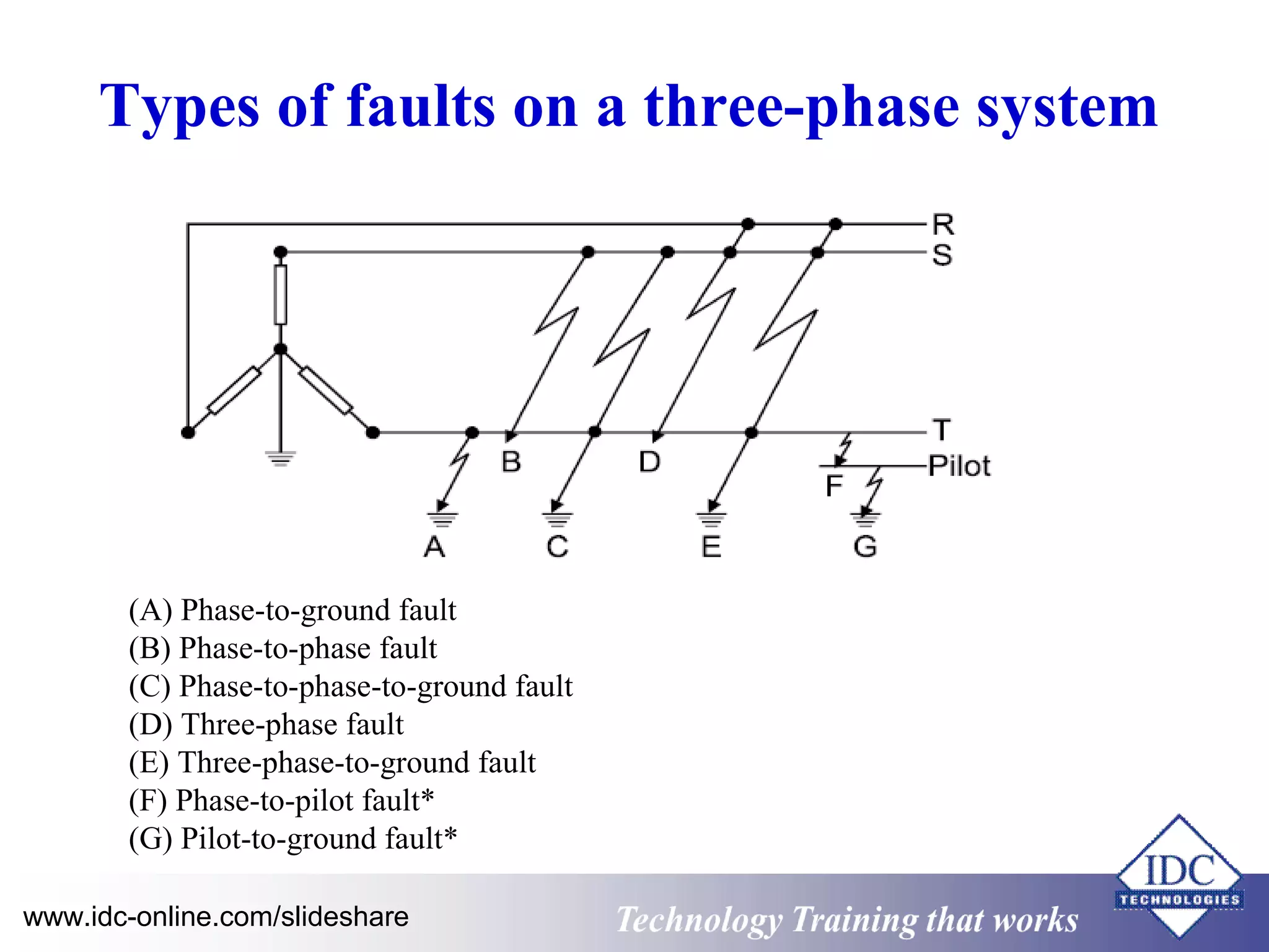


The document discusses the installation, programming, and commissioning of power system protection relays and the importance of maintaining efficient power system operations. It outlines methods for avoiding breakdowns, describes essential components of protection systems, different distribution systems, and the consequences of faults. Additionally, it covers grounding techniques, fuse selection, and the role of instrument transformers in power systems.


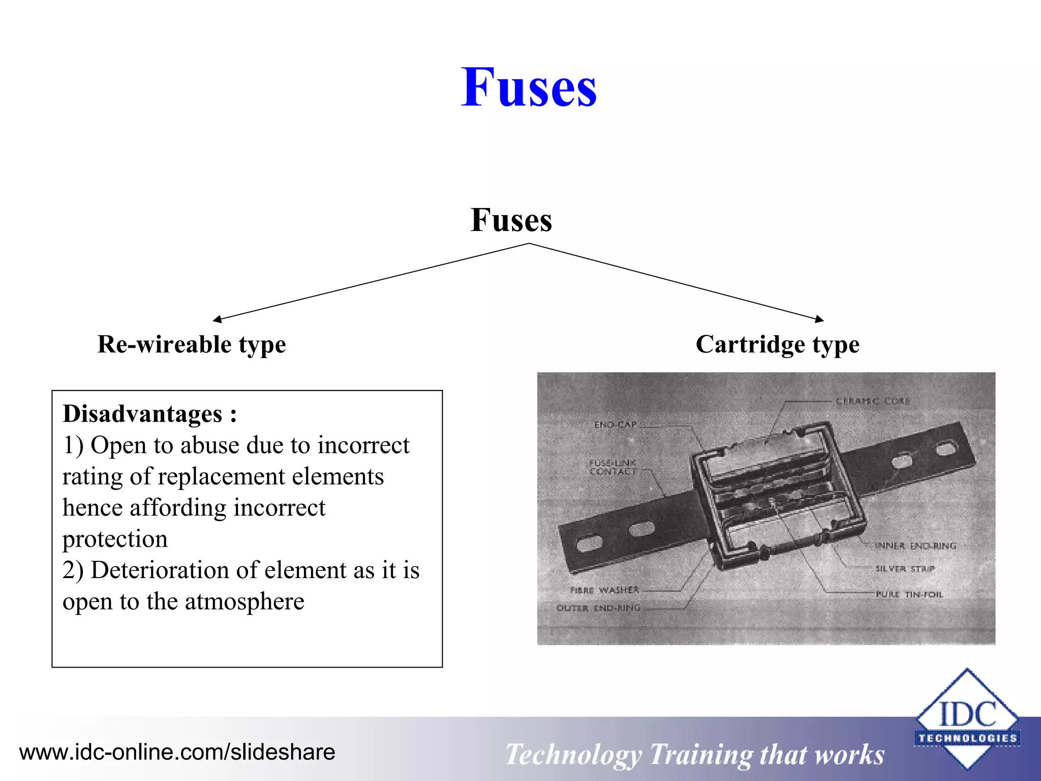
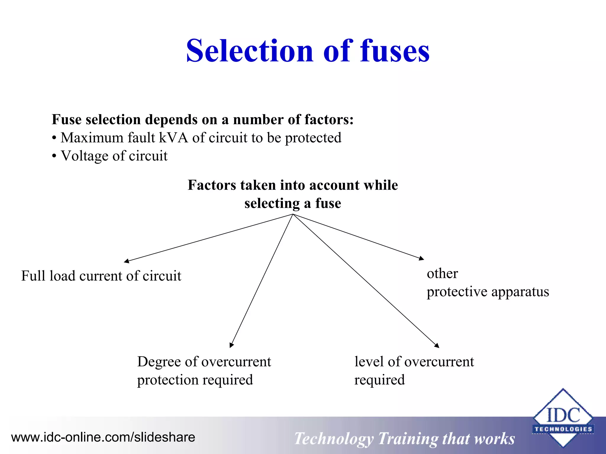
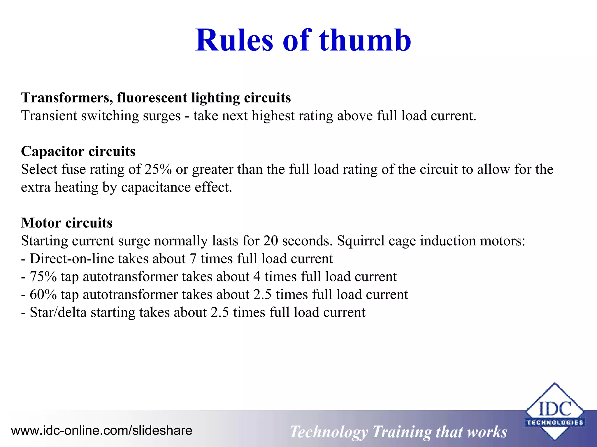
![See4423 chapter1 introduction[1]](https://cdn.slidesharecdn.com/ss_thumbnails/see4423chapter1introduction1-110307213255-phpapp01-thumbnail.jpg?width=640&height=640&fit=bounds)


