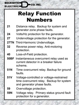
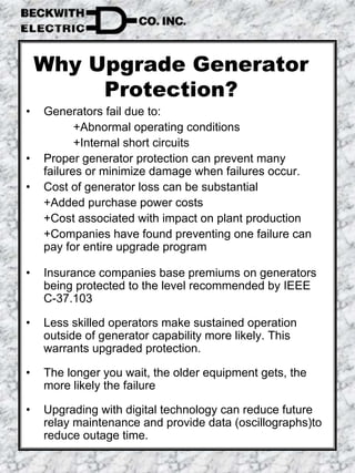
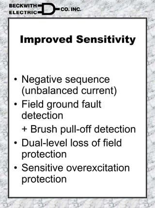
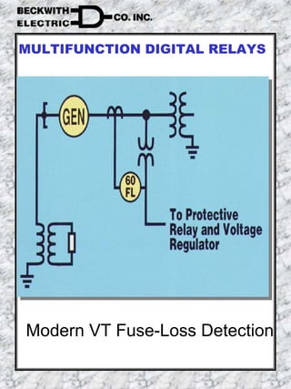
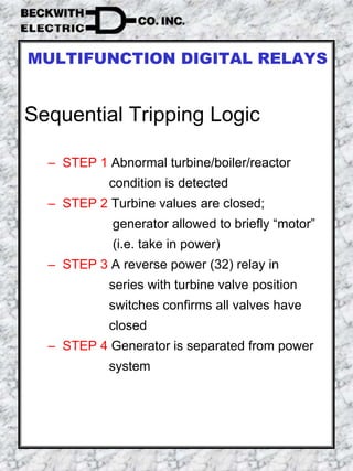
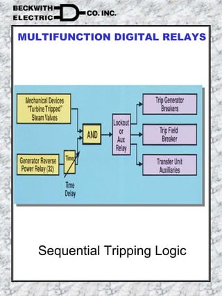
Upgrading
Generator
Protection and
Grounding for
Industrial
Generators-
Why & How
Chuck Mozina
Beckwith Electric Co., Inc.
Section I
Introduction
A major US manufacturer of :
– Digital multifunction generator
and transformer protection
– Generator synchronizing and
bus transfer equipment
– Voltage control devices for
LTC transformer, regulators,
and capacitor banks
– Packaged systems using
Beckwith products
– Family-owned
company founded
by Mr. Bob Beckwith
– Formed May 1967 in Chicago,
Illinois
– Moved in 1974 to Largo,
Florida
– Additional Facility in October
1992
– Temporary Facility in October 1992
(Result of tornado damage)
– New facility November 1993
ISO Registered
The Instructor
Chuck Mozina is Manager of Application Engineering for
Protection and Protection Systems at Beckwith Electric Co. He
is responsible for the application of Beckwith products and
systems used in generator protection and intertie protection,
synchronizing and bus transfer schemes.
Chuck is an active member of the IEEE Power System Relay
Committee and is the past chairman of the Rotating Machinery
Subcommittee. He is active in the IEEE IAS I&CPS committee
which addresses industrial system protection. He is the U.S.
representative to the CIGRE Study Committee 34 on System
Protection and chairs a CIGRE working group on generator
protection. He also chaired the IEEE task force which produced
the tutorial “The Protection of Synchronous Generators,” which
won the PSRC‘s 1995 Outstanding Working Group Award.
Chuck is the 1993 recipient of the PSRC‘s Career Service
Award.
Chuck has a Bachelor of Science in electrical engineering from
Purdue University and has authored a number of papers and
magazine articles on protective relaying. He has over 25 years
of experience as a protective engineer at Centerior Energy, a
major investor-owned utility in Cleveland, Ohio where he was
the Manager of the System Protection Section. He is also a
former instructor in the Graduate School of Electrical
Engineering at Cleveland State University as well as a
registered Engineer in the state of Ohio.
Relay Seminar
October 14 – 19, 2001
Clearwater, Florida
Beckwith Electric has announced a date for
the next Relay Seminar, which will cover
Generator, Transformer, and Interconnection
Protection.
To sign up to be on the mailing list and
receive seminar details, please visit:
www.beckwithelectric.com/semreg.htm
Seminar Outline
Day 1 — AM
Generator Protection M-3425
Fundamentals of Digital Protection
• Generator basics and generator grounding
– Generator fundamentals
– Generator grounding
• Traditional
• IAS proposed hybrid scheme
– Industry standards
– Function numbers
• Developing a protection upgrade program
– Why upgrade at all
– Improved sensitivity
– New protection areas
– Special protection applications
– Basic upgrade options
• Use of digital technology to upgrade
– Beckwith M-3425
– Features
– Software, oscillograph demonstration
• Questions
Section II
Fundamentals of Digital
Protection
General Information on
Generator Protection
Generator fundamentals
Industry standards
Function numbers
Functional breakdown
Fundamentals
Fundamental Section
Basic synchronous generators
Connections to the system
Generator grounding
C37 guidelines
Device numbers
Ib
Basic Synchronous
Generator
Gen
3-Ø
Electrical
Output
DC Field Source
Ia
Ic
Prime Mover
(Mechanical Input)
Synchronous
Generator Types
Direct Connected
Generator to Power
System
G
POWER SYSTEM
LOAD BUS
AUXILIARY
LOAD
LOAD LOAD
Unit Connected
Generator to Power
System
G
AUXILIARY
LOAD
POWER SYSTEM
Low Impedance
Grounding
* RESISTOR
OR
REACTOR
*
GENERATOR
WINDINGS
High Impedance
Grounding
* RESISTOR
*
GENERATOR
WINDINGS
Generator
Short-Circuit Current
(Xd” Tdo”)
(Xd’ Tdo’)
(I)
Generator Terminal
Fault Current
Key Industry
Guides & Standards
Key Industry
Guides & Standards
IEEE/ANSI
C-37.102-1995
C-37.101-1992
C-37.106-1992
Guide for AC
Generator
Protection
Guide for Generator
Ground Protection
Guide for Abnormal
Frequency
Protection for
Power Generating
Plant
Relay Function
Numbers
21 Distance relay. Backup for system and
generator zone phase faults.
24 Volts/Hz protection for the generator.
27 Undervoltage protection for the generator.
27TN Third-Harmonic Undervoltage.
32 Reverse power relay. Anti-motoring
protection.
40 Loss-of-Field protection.
50BF Instantaneous overcurrent relay used as
current detector in a breaker failure
scheme.
51N Time overcurrent relay. Backup for ground
faults.
51V Voltage-controlled or voltage-restrained
time overcurrent relay. Backup for system
and generator phase faults.
59 Overvoltage protection.
59N Voltage relay. Primary status ground fault
protection for a generator.
60FL Voltage balance relay. Detection of
blown potential transformer fuses.
62B Breaker failure timer.
64F Primary protection for rotor ground
faults.
78 Loss of synchronism protection.
81O/U Frequency relay. Both under frequency
and overfrequency protection.
86 Hand-reset lockout auxiliary relay.
87G Differential relay. Primary phase-fault
protection for the generator.
87GD Sensitive ground fault protection for the
generator.
87T Differential relay. Primary protection for
the transformer. May be used to provide
phase fault backup for the generator in
some station arrangements.
87U Differential relay for overall unit and
transformer.
Relay Function
Numbers
M-3425
Typical Connection Diagram
Standard Protective Functions
This function provides control for the
function to which it points: it cannot be
used independently.
Premium Protective Functions
NOTE: Some functions are mutually
exclusive; see Instruction Book for details.
Utility System
52
Unit
3
IN
52
Gen
M-3425
59 2481 27
50
BF-Ph
46
87
CT
VT
78 51T
+
-
64F
Generator
Field
60FL 40
27
51V 50 21 32 50
27
51NCT
R
M-3425
Low-impedance Grounding
with Overcurrent Stator
Ground Fault Protection
50N
87GD
59N27TN
32
27
R
M-3425
High-impedance Stator Ground
Fault with Third Harmonic 100%
Ground Fault Protection
3
CT
50
DT
50BF-
N
Section III
Upgrading Generator Protection
Using Digital Technology
Upgrading Generator
Protection Using
Digital Technology
Charles J. Mozina
Beckwith Electric Company
Why Upgrade Generator
Protection?
• Generators fail due to:
+Abnormal operating conditions
+Internal short circuits
• Proper generator protection can prevent many
failures or minimize damage when failures occur.
• Cost of generator loss can be substantial
+Added purchase power costs
+Cost associated with impact on plant production
+Companies have found preventing one failure can
pay for entire upgrade program
• Insurance companies base premiums on generators
being protected to the level recommended by IEEE
C-37.103
• Less skilled operators make sustained operation
outside of generator capability more likely. This
warrants upgraded protection.
• The longer you wait, the older equipment gets, the
more likely the failure
• Upgrading with digital technology can reduce future
relay maintenance and provide data (oscillographs)to
reduce outage time.
Areas of Protection Upgrade On
Older Generators
– Improved sensitivity
– New or additional protection areas
– Special protection application
considerations
MULTIFUNCTION DIGITAL RELAYS
Improved Sensitivity
– Negative sequence (unbalanced
current)
– Field ground 100% fault detection
+Brush pull-off detection
– Dual-level loss-of field protection
– Sensitive overexcitation protection
MULTIFUNCTION DIGITAL RELAYS
New or Additional
Protection Areas
– Inadvertent generator
energizing
– VT fuse-loss protection
– Sequential tripping
– Oscillographic monitoring
MULTIFUNCTION DIGITAL RELAYS
Special Protection ApplicationSpecial Protection Application
ConsiderationsConsiderations
Generator breaker failureGenerator breaker failure
Over/under frequencyOver/under frequency
Improved Sensitivity
• Negative sequence
(unbalanced current)
• Field ground fault
detection
+ Brush pull-off detection
• Dual-level loss of field
protection
• Sensitive overexcitation
protection
Negative Sequence
MULTIFUNCTION DIGITAL RELAYS
Negative Sequence (46)
–Unbalanced phase currents
create negative sequence
current in generator stator,
MULTIFUNCTION DIGITAL RELAYS
Negative Sequence (46)
– Negative sequence current interacts
with normal positive sequence current
to induce a double frequency current
(120 Hz)
– Current (120 Hz) is induced into rotor
causing surface heating
MULTIFUNCTION DIGITAL RELAYS
Currents in the Rotor Surface
MULTIFUNCTION DIGITAL RELAYS
Negative Sequence (46)
Salient Pole
With connected amortisseur
10
With non-connected amortisseur
5
Cylindrical
Indirectly
10
Directly cooled - to 960 MVA
8
961 to 1200 MVA
6
1200 to 1500 MVA
5
% Stator
Rating
MULTIFUNCTION DIGITAL RELAYS
Negative Sequence (46)
–Generator has established
short-time rating,
MULTIFUNCTION DIGITAL RELAYS
Negative Sequence (46)
Two Types of Relays
1. ELECTROMECHANICAL
– Sensitivity restricted to about
60% I2 of generator ratings
– Fault backup provided
– Generally insensitive to load
balances or open conductors
MULTIFUNCTION DIGITAL RELAYS
Negative Sequence (46)
Two Types of Relays
1. DIGITAL AND STATIC
–Protects generator down to
its continuous I2 rating
–Can detect open conductor
conditions
MULTIFUNCTION DIGITAL RELAYS
Advanced Protection
Functions
Field (Rotor) Ground
Fault Protection (64F)
Insurance companies tell us this
is the most frequent internal
generator fault
Review existing 64F voltage
protection methods
Discuss a new 64F injection
method
Typical Generator
Field Circuit
The first ground fault will:
establish a ground reference
making a second ground fault
more likely
increase stress to ground at other
points in field winding
Ground #1
Typical Generator
Field Circuit
The second ground fault will:
short out part of field winding
causing unit vibrations
cause rotor heating from
unbalanced currents
cause arc damage at the points of
fault
Ground #2
Ground #1
Field Ground Fault Protection
Detection Using a DC Source
Field Ground Fault Protection
Detection Using a Voltage
Divider
Field Ground Fault Protection
Using Injection Voltage Signal
Field Ground Fault Protection
Real-Time Insulation
Measurements
Field Insulation
Real-Time Monitoring
Advanced Protection
Functions
Brush lift-off detection (64B)
– Brushes on older generators
are a maintenance headache
for plant personnel
– When brushes should be
replaced or re-adjusted is
important diagnostic
information
– If brushes open on an in-
service generator they cause:
• arc damage to brush mounting
structure
• eventual unit tripping by loss-of-
field protection
Field Ground Fault Protection
Using Injection Voltage Signal
Brush lift-off
Analyzer voltage
return signal
Brush Lift-off Voltage
Return Signal
Ground Brush Lift-off
When the ground brush lifts off
the rotor
– Low resistance path to ground for
stray rotor flux is removed
– Generator bearings carry stray shaft
ground current
– Bearing will pit and will need to be
replaced
Dual-Level
Loss-of-Field
Protection
Older, Single-Zone Off-Set Mho Relay
Loss-of-Field Characteristics
MULTIFUNCTION DIGITAL RELAYS
Loss-of-Field Using Two-Zone
Off-Set Mho Method
MULTIFUNCTION DIGITAL RELAYS
Sensitive
Overexcitation
Protection
MULTIFUNCTION DIGITAL RELAYS
Overexcitation /
Volts per Hertz (24)
GENERATOR
TRANSFORMER ≈
EXCITATION
Voltage V
Freq. Hz
GENERATOR LIMITS (ANSI C 50.13)
Full Load V/Hz = 1.05 pu
No Load V/Hz = 1.05 pu
TRANSFORMER LIMITS
Full Load V/Hz = 1.05 pu (HV Terminals)
No Load V/Hz = 1.10 pu (HV Terminals)
MULTIFUNCTION DIGITAL RELAYS
Overexcitation/
Volts per Hertz (24)
CAUSES OF V/HZ PROBLEMS
• Generator voltage regulator problems
- operating error during off-line manual
regulator operation
- control failure
- loss of VT regulator supply voltage
- overexcitation when regulator is on–line
• System problems
- unit load rejection: full load, partial
rejection
- power system islanding during major
distrubances
MULTIFUNCTION DIGITAL RELAYS
Overexcitation/
Volts per Hertz (24)
PHYSICAL INSIGHTS
• As voltage rises above rating leakage flux
increases
• Leakage flux induces current in transformer
support
structure causing rapid localized heating
MULTIFUNCTION DIGITAL RELAYS
Typical Relay Characteristics forTypical Relay Characteristics for
DualDual--Level DefiniteLevel Definite--TimeTime
V/Hz ProtectionV/Hz Protection
MULTIFUNCTION DIGITAL RELAYS
OptimumOptimum OverexcitationOverexcitation
ProtectionProtection
MULTIFUNCTION DIGITAL RELAYS
New or Additional Protection
Areas
• Inadvertent generator energizing
• VT fuse-loss protection
• Sequential tripping
• Oscillographic monitoring
MULTIFUNCTION DIGITAL RELAYS
Inadvertent Generator
Energizing
MULTIFUNCTION DIGITAL RELAYS
How Inadvertent Energizing
Has Occurred
– Operating errors
– Breaker head flashover
– Control circuit malfunctions
– Combination of above
MULTIFUNCTION DIGITAL RELAYS
Generator Response and Damage to
Three-Phase Energizing
– Generator behaves as an induction
motor
– Rotating flux induced into the
generator rotor
– Resulting rotor current is forced into
negative sequence path in rotor body
MULTIFUNCTION DIGITAL RELAYS
Inadvertent Energizing Equivalent
Circuit
MULTIFUNCTION DIGITAL RELAYS
Inadvertent Energizing Function
Logic Diagram
MULTIFUNCTION DIGITAL RELAYS
VT Fuse-Loss Protection
MULTIFUNCTION DIGITAL RELAYS
Application of Voltage Balance
Relay Protection
MULTIFUNCTION DIGITAL RELAYS
Modern VT Fuse-Loss Detection
MULTIFUNCTION DIGITAL RELAYS
Sequential Tripping
MULTIFUNCTION DIGITAL RELAYS
Sequential Tripping Logic
– Used in steam turbine generators to
prevent overspeed
– Recommended by manufacturers of
steam turbine generators as a result
of field experience
– This trip mode used only for
boiler/reactor or turbine mechanical
problems
– electrical protection should not trip
through this mode
MULTIFUNCTION DIGITAL RELAYS
Sequential Tripping Logic
– STEP 1 Abnormal turbine/boiler/reactor
condition is detected
– STEP 2 Turbine values are closed;
generator allowed to briefly “motor”
(i.e. take in power)
– STEP 3 A reverse power (32) relay in
series with turbine valve position
switches confirms all valves have
closed
– STEP 4 Generator is separated from power
system
MULTIFUNCTION DIGITAL RELAYS
Sequential Tripping Logic
MULTIFUNCTION DIGITAL RELAYS
Oscillographic
Monitoring
MULTIFUNCTION DIGITAL RELAYS
Benefits
– Determine if relay and circuit breaker
operated properly
– relay control problem
– generator experience fault / abnormal
conditions
– Speed generator return to service
– identify type of testing needed
– provide data to generator manufacturer
– Gives relay engineer data to force unit
off-line for inspection
– Uncovers unexpected problems: I.e.
synchronizing
Oscillographic MonitoringOscillographicOscillographic MonitoringMonitoring
MULTIFUNCTION DIGITAL RELAYS
Digital Relay Oscillograph
MULTIFUNCTION DIGITAL RELAYS
Special Protection
Application
Considerations
Generator breaker failure
Over/under frequency
MULTIFUNCTION DIGITAL RELAYS
Generator Breaker
Failure
MULTIFUNCTION DIGITAL RELAYS
Typical Transmission Line Breaker
Failure Functional Diagram
MULTIFUNCTION DIGITAL RELAYS
Functional Diagram of a Generator
Breaker Failure Scheme
MULTIFUNCTION DIGITAL RELAYS
Under/Overfrequency
(81U/81O)
MULTIFUNCTION DIGITAL RELAYS
Under/Overfrequency
(81U/81O)
Underfrequency (81U)
Generator Limits • Generator overloaded high strator
current
• Heating limits need to reduce
output
•Overexcitation same as 24
Overvoltage (V/Hz)
•Turbine blade resonance
•All system generators are
overloaded
•System load shedding via 81U to
restore balance
•Need to coordinate tripping with
system loadshedding.
Turbine Limits
(Steam/GT)
System Problems
MULTIFUNCTION DIGITAL RELAYS
FIGURE 1 Generator Capability Versus Frequency
FIGURE 2 Generator Short-Term Thermal Capability
MULTIFUNCTION DIGITAL RELAYS
Under/Under/OverfrequencyOverfrequency
(81U/81O)(81U/81O)
OverfrequencyOverfrequency (81O)(81O)
Generator Limits
Turbine Limits
(Steam/GT)
System Problems
• None published
•Similar limits to
underfrequency
•Overspeed trip at
110%
•More generation than
load
•Governor actions to
reduce MW output
MULTIFUNCTION DIGITAL RELAYS
FIGURE 3
Steam Turbine Partial or Full-Load Operating
Limitations During Abnormal Frequency
MULTIFUNCTION DIGITAL RELAYS
ECAR Document # 3
Generator Under Frequency
Tripping Requirements
0 minutesBelow 58.2 Hz
7.0 minutes58.5 - 58.2 Hz
30.0 minutes59.5 - 58.5 Hz
Unlimited60.0 – 59.5 Hz
Time Delay
Before Isolation
Frequency
MULTIFUNCTION DIGITAL RELAYS
FIGURE 4
Example of Trip Characteristics:
Overfrequency and Underfrequency
MULTIFUNCTION DIGITAL RELAYS
Use of Digital
Technology to
Implement and
Upgrade Program
MULTIFUNCTION DIGITAL RELAYS
Two Basic Design Options
– Retain Existing Protection
– add additional functions to upgrade
to current standards
– Remove all existing protection
– upgrade with all new protection
MULTIFUNCTION DIGITAL RELAYS
Dual-Relay Approach for Major
Generators
MULTIFUNCTION DIGITAL RELAYS
Multifunction Relays Are The
Right Choice, Either Way
– Panel space savings
– Oscillographic capability
– Communication (RS232 & RS485)
– Low CT and VT burdens
– Self diagnostic
MULTIFUNCTION DIGITAL RELAYS
Conclusions
– There are a number of serious
protection shortcomings on
generators with relays older than 20
years
– This paper attempted to bring those
risks to the attention of
utilities/generator owners
MULTIFUNCTION DIGITAL RELAYS
Conclusions
– Utilities/generator owners should
address these risks through
comprehensive upgrade programs to
protect their generator investment
– Multifunction digital relays are an
ideal, cost effective way to
implement such a program
Section IV
Beckwith M-3425
Generator Relay
Function & Features
The World’s Leading
Manufacturer of
Digital Generator
Protection Proudly
Presents the New
M-3425 Relay
The World’s Leading
Manufacturer of
Digital Generator
Protection Proudly
Presents the New
M-3425 Relay
Digital Integrated Protection System® for
Generators of All Sizes
What’s New
from Beckwith in
Generator Protection
New Features
• Field Ground (64F)
• Out-of-Step(78)
• Split Phase Diff.. (50DT)
• Stator Thermal Overcurrent Protection
(51T)
New FeaturesNew Features
•• Field Ground (64F)Field Ground (64F)
•• OutOut--ofof--Step(78)Step(78)
•• Split Phase Diff.. (50DT)Split Phase Diff.. (50DT)
•• Stator Thermal Overcurrent ProtectionStator Thermal Overcurrent Protection
(51T)(51T)
M-3420M-3420 M-3430M-3430
New
M-3425
New
M-3425
995 relays in service
worldwide
489 relays in service
worldwide
MM--34253425
Typical Connection DiagramTypical Connection Diagram
Standard Protective Functions
This function provides control for the
function to which it points: it cannot be
used independently.
Premium Protective Functions
NOTE: Some functions are mutually
exclusive; see Instruction Book for details.
Utility System
52
Unit
3
IN
52
Gen
M-3425
59 2481 27
50
BF-Ph
46
87
CT
VT
78 51T
+
-
64F
Generator
Field
60FL 40
27
51V 50 21 32 50
27
51NCT
R
M-3425
Low-impedance Grounding
with Overcurrent Stator
Ground Fault Protection
50N
87GD
59N27TN
32
27
R
M-3425
High-impedance Stator Ground
Fault with Third Harmonic 100%
Ground Fault Protection
3
CT
50
DT
50BF-
N
Standard M-3425
Functions
• Overexcitation (V/Hz) protection (24)with both
discrete time and inverse time curves
• 100% Stator Ground Fault Protection via third
harmonic neutral undervoltage (27TN)
• Sensitive dual-setpoint reverse power, low forward
power or over power detection, one of which can
be used for sequential tripping (32)
• Dual-zone, offset-mho loss-of-field protection (40)
• Sensitive negative sequence overcurrent
protection and alarm (46)
• Generator Breaker Failure protection (50BF)
• Inadvertant generator energizing protection
(50/27)
• Definite Time Overcurrent (50DT) can be used for
split phase differential applications
• Neutral inverse time overcurrent (51N) and
instantaneous overcurrent (50N) protection
Standard MStandard M--3425 Functions3425 Functions
ThreeThree--phase inverse time overcurrentphase inverse time overcurrent
(51V) and instantaneous overcurrent (50)(51V) and instantaneous overcurrent (50)
protectionprotection
Phase overvoltage (59) and undervoltagePhase overvoltage (59) and undervoltage
(27) protection(27) protection
Generator ground fault protection (59N)Generator ground fault protection (59N)
VT fuseVT fuse--loss detection and blocking (60FL)loss detection and blocking (60FL)
FourFour--step Over/Underfrequency (81)step Over/Underfrequency (81)
protectionprotection
Two step Rate of Change of FrequencyTwo step Rate of Change of Frequency
(81R)(81R)
Generator phase differential protectionGenerator phase differential protection
(87) and ground differential (87GD)(87) and ground differential (87GD)
protectionprotection
External Function allows external devicesExternal Function allows external devices
to trip through Mto trip through M--3425 Generator3425 Generator
Protection RelayProtection Relay
Premium MPremium M--3425 Functions3425 Functions
Field ground using advanced
injection system (64F)
Stator thermal protection using
positive sequence inverse
overcurrent (51T)
Additional Standard
M-3425 Functions
• Eight programmable outputs and six
programmable inputs
• Oscillography recording (170 cycles)
• Time-stamped target storage for 24 events.
• Metering of all measured parameters
• Two RS-232C and one RS-485 communications
ports
• M-3425 IPScom® Communications and Setting
Software
• Includes Modbus and BECO2200 protocols
• Standard 19" rack-mount design
• Removable printed circuit board and power
supply
• Both 50 and 60 Hz models available
• Both 1 and 5 A rated CT inputs available
• Additional trip inputs for externally connected
devices
• IRIG-B time synchronization
MM--34253425
External ConnectionsExternal Connections
A
B
C
50
Low
Impedance
Grounding
52
Gen
High Impedance Grounding
a b c
A B C
52b
2
M-3425 Three-Line
Connection Diagram
M-3425Other
Relays
UTILITY SYSTEM
M-3425
Three VT Wye-Wye
Connection
Three VT Wye-Wye
Connection Ungrounded
Three VT Open-Delta
Connection
51
48 49
46 47 10
11
Optional
Field
Ground
Module
58 59
56 57
54 55
M-3425
M-3425
52 53
M-3425
M-3425
M-3425
45
44
42 43 40 41 38 39 42 43 40 41 38 39 42 43 40 41 38 39
Generator
Other
Relays
M-3425
Power Supply
Power Supply
(Optional)
Programmable
Gain Amplifier
M
U
X
Digital Signal
Processor
(DSP)
TMS 320C52
2K byte
Dual-Ported
RAM
2-Line by 24-
Character
Liquid Crystal
Display
126K byte
RAM
256K byte
Flash-
Programmable
ROM
Host Processor
10 MHz Zilog
64181
512 Byte
EEPROM
8K byte RAM,
Clock with
battery backup
MMI
Module
(Optional)
Target
Module
(Optional)
RS232 and
RS485
Communi-
cation ports
IRIG-B
Time Code
input
Relay
Outputs
Contact
Inputs
Anti-Aliasing Low-Pass Filters (LPF)
Analog Multiplexer
VTs & CTs
Va
Vb
Vc
Vn
ia
ib
ic
iA
iB
iC
iN
32K X 16
RAM
Address/Data Bus
14-bit
Analog-to-
Digital
Converter
M-3425
Hardware Block Diagram

Upgrading gen protect and grounding

  • 1.
  • 2.
  • 3.
    A major USmanufacturer of : – Digital multifunction generator and transformer protection – Generator synchronizing and bus transfer equipment – Voltage control devices for LTC transformer, regulators, and capacitor banks – Packaged systems using Beckwith products
  • 4.
    – Family-owned company founded byMr. Bob Beckwith – Formed May 1967 in Chicago, Illinois – Moved in 1974 to Largo, Florida – Additional Facility in October 1992
  • 5.
    – Temporary Facilityin October 1992 (Result of tornado damage)
  • 6.
    – New facilityNovember 1993
  • 7.
  • 8.
    The Instructor Chuck Mozinais Manager of Application Engineering for Protection and Protection Systems at Beckwith Electric Co. He is responsible for the application of Beckwith products and systems used in generator protection and intertie protection, synchronizing and bus transfer schemes. Chuck is an active member of the IEEE Power System Relay Committee and is the past chairman of the Rotating Machinery Subcommittee. He is active in the IEEE IAS I&CPS committee which addresses industrial system protection. He is the U.S. representative to the CIGRE Study Committee 34 on System Protection and chairs a CIGRE working group on generator protection. He also chaired the IEEE task force which produced the tutorial “The Protection of Synchronous Generators,” which won the PSRC‘s 1995 Outstanding Working Group Award. Chuck is the 1993 recipient of the PSRC‘s Career Service Award. Chuck has a Bachelor of Science in electrical engineering from Purdue University and has authored a number of papers and magazine articles on protective relaying. He has over 25 years of experience as a protective engineer at Centerior Energy, a major investor-owned utility in Cleveland, Ohio where he was the Manager of the System Protection Section. He is also a former instructor in the Graduate School of Electrical Engineering at Cleveland State University as well as a registered Engineer in the state of Ohio.
  • 9.
    Relay Seminar October 14– 19, 2001 Clearwater, Florida Beckwith Electric has announced a date for the next Relay Seminar, which will cover Generator, Transformer, and Interconnection Protection. To sign up to be on the mailing list and receive seminar details, please visit: www.beckwithelectric.com/semreg.htm
  • 10.
    Seminar Outline Day 1— AM Generator Protection M-3425 Fundamentals of Digital Protection • Generator basics and generator grounding – Generator fundamentals – Generator grounding • Traditional • IAS proposed hybrid scheme – Industry standards – Function numbers • Developing a protection upgrade program – Why upgrade at all – Improved sensitivity – New protection areas – Special protection applications – Basic upgrade options • Use of digital technology to upgrade – Beckwith M-3425 – Features – Software, oscillograph demonstration • Questions
  • 11.
    Section II Fundamentals ofDigital Protection
  • 12.
    General Information on GeneratorProtection Generator fundamentals Industry standards Function numbers Functional breakdown
  • 13.
  • 14.
    Fundamental Section Basic synchronousgenerators Connections to the system Generator grounding C37 guidelines Device numbers
  • 15.
    Ib Basic Synchronous Generator Gen 3-Ø Electrical Output DC FieldSource Ia Ic Prime Mover (Mechanical Input)
  • 16.
  • 17.
    Direct Connected Generator toPower System G POWER SYSTEM LOAD BUS AUXILIARY LOAD LOAD LOAD
  • 18.
    Unit Connected Generator toPower System G AUXILIARY LOAD POWER SYSTEM
  • 19.
  • 20.
  • 21.
  • 22.
  • 24.
  • 25.
    Key Industry Guides &Standards IEEE/ANSI C-37.102-1995 C-37.101-1992 C-37.106-1992 Guide for AC Generator Protection Guide for Generator Ground Protection Guide for Abnormal Frequency Protection for Power Generating Plant
  • 26.
    Relay Function Numbers 21 Distancerelay. Backup for system and generator zone phase faults. 24 Volts/Hz protection for the generator. 27 Undervoltage protection for the generator. 27TN Third-Harmonic Undervoltage. 32 Reverse power relay. Anti-motoring protection. 40 Loss-of-Field protection. 50BF Instantaneous overcurrent relay used as current detector in a breaker failure scheme. 51N Time overcurrent relay. Backup for ground faults. 51V Voltage-controlled or voltage-restrained time overcurrent relay. Backup for system and generator phase faults. 59 Overvoltage protection. 59N Voltage relay. Primary status ground fault protection for a generator.
  • 27.
    60FL Voltage balancerelay. Detection of blown potential transformer fuses. 62B Breaker failure timer. 64F Primary protection for rotor ground faults. 78 Loss of synchronism protection. 81O/U Frequency relay. Both under frequency and overfrequency protection. 86 Hand-reset lockout auxiliary relay. 87G Differential relay. Primary phase-fault protection for the generator. 87GD Sensitive ground fault protection for the generator. 87T Differential relay. Primary protection for the transformer. May be used to provide phase fault backup for the generator in some station arrangements. 87U Differential relay for overall unit and transformer. Relay Function Numbers
  • 28.
    M-3425 Typical Connection Diagram StandardProtective Functions This function provides control for the function to which it points: it cannot be used independently. Premium Protective Functions NOTE: Some functions are mutually exclusive; see Instruction Book for details. Utility System 52 Unit 3 IN 52 Gen M-3425 59 2481 27 50 BF-Ph 46 87 CT VT 78 51T + - 64F Generator Field 60FL 40 27 51V 50 21 32 50 27 51NCT R M-3425 Low-impedance Grounding with Overcurrent Stator Ground Fault Protection 50N 87GD 59N27TN 32 27 R M-3425 High-impedance Stator Ground Fault with Third Harmonic 100% Ground Fault Protection 3 CT 50 DT 50BF- N
  • 29.
    Section III Upgrading GeneratorProtection Using Digital Technology
  • 30.
    Upgrading Generator Protection Using DigitalTechnology Charles J. Mozina Beckwith Electric Company
  • 31.
    Why Upgrade Generator Protection? •Generators fail due to: +Abnormal operating conditions +Internal short circuits • Proper generator protection can prevent many failures or minimize damage when failures occur. • Cost of generator loss can be substantial +Added purchase power costs +Cost associated with impact on plant production +Companies have found preventing one failure can pay for entire upgrade program • Insurance companies base premiums on generators being protected to the level recommended by IEEE C-37.103 • Less skilled operators make sustained operation outside of generator capability more likely. This warrants upgraded protection. • The longer you wait, the older equipment gets, the more likely the failure • Upgrading with digital technology can reduce future relay maintenance and provide data (oscillographs)to reduce outage time.
  • 32.
    Areas of ProtectionUpgrade On Older Generators – Improved sensitivity – New or additional protection areas – Special protection application considerations MULTIFUNCTION DIGITAL RELAYS
  • 33.
    Improved Sensitivity – Negativesequence (unbalanced current) – Field ground 100% fault detection +Brush pull-off detection – Dual-level loss-of field protection – Sensitive overexcitation protection MULTIFUNCTION DIGITAL RELAYS
  • 34.
    New or Additional ProtectionAreas – Inadvertent generator energizing – VT fuse-loss protection – Sequential tripping – Oscillographic monitoring MULTIFUNCTION DIGITAL RELAYS
  • 35.
    MULTIFUNCTION DIGITAL RELAYS SpecialProtection ApplicationSpecial Protection Application ConsiderationsConsiderations Generator breaker failureGenerator breaker failure Over/under frequencyOver/under frequency
  • 36.
    Improved Sensitivity • Negativesequence (unbalanced current) • Field ground fault detection + Brush pull-off detection • Dual-level loss of field protection • Sensitive overexcitation protection
  • 37.
  • 38.
    Negative Sequence (46) –Unbalancedphase currents create negative sequence current in generator stator, MULTIFUNCTION DIGITAL RELAYS
  • 39.
    Negative Sequence (46) –Negative sequence current interacts with normal positive sequence current to induce a double frequency current (120 Hz) – Current (120 Hz) is induced into rotor causing surface heating MULTIFUNCTION DIGITAL RELAYS
  • 40.
    Currents in theRotor Surface MULTIFUNCTION DIGITAL RELAYS
  • 41.
    Negative Sequence (46) SalientPole With connected amortisseur 10 With non-connected amortisseur 5 Cylindrical Indirectly 10 Directly cooled - to 960 MVA 8 961 to 1200 MVA 6 1200 to 1500 MVA 5 % Stator Rating MULTIFUNCTION DIGITAL RELAYS
  • 42.
    Negative Sequence (46) –Generatorhas established short-time rating, MULTIFUNCTION DIGITAL RELAYS
  • 43.
    Negative Sequence (46) TwoTypes of Relays 1. ELECTROMECHANICAL – Sensitivity restricted to about 60% I2 of generator ratings – Fault backup provided – Generally insensitive to load balances or open conductors MULTIFUNCTION DIGITAL RELAYS
  • 44.
    Negative Sequence (46) TwoTypes of Relays 1. DIGITAL AND STATIC –Protects generator down to its continuous I2 rating –Can detect open conductor conditions MULTIFUNCTION DIGITAL RELAYS
  • 45.
    Advanced Protection Functions Field (Rotor)Ground Fault Protection (64F) Insurance companies tell us this is the most frequent internal generator fault Review existing 64F voltage protection methods Discuss a new 64F injection method
  • 46.
    Typical Generator Field Circuit Thefirst ground fault will: establish a ground reference making a second ground fault more likely increase stress to ground at other points in field winding Ground #1
  • 47.
    Typical Generator Field Circuit Thesecond ground fault will: short out part of field winding causing unit vibrations cause rotor heating from unbalanced currents cause arc damage at the points of fault Ground #2 Ground #1
  • 48.
    Field Ground FaultProtection Detection Using a DC Source
  • 49.
    Field Ground FaultProtection Detection Using a Voltage Divider
  • 50.
    Field Ground FaultProtection Using Injection Voltage Signal
  • 51.
    Field Ground FaultProtection Real-Time Insulation Measurements Field Insulation Real-Time Monitoring
  • 52.
    Advanced Protection Functions Brush lift-offdetection (64B) – Brushes on older generators are a maintenance headache for plant personnel – When brushes should be replaced or re-adjusted is important diagnostic information – If brushes open on an in- service generator they cause: • arc damage to brush mounting structure • eventual unit tripping by loss-of- field protection
  • 53.
    Field Ground FaultProtection Using Injection Voltage Signal Brush lift-off Analyzer voltage return signal
  • 54.
  • 55.
    Ground Brush Lift-off Whenthe ground brush lifts off the rotor – Low resistance path to ground for stray rotor flux is removed – Generator bearings carry stray shaft ground current – Bearing will pit and will need to be replaced
  • 56.
  • 57.
    Older, Single-Zone Off-SetMho Relay Loss-of-Field Characteristics MULTIFUNCTION DIGITAL RELAYS
  • 58.
    Loss-of-Field Using Two-Zone Off-SetMho Method MULTIFUNCTION DIGITAL RELAYS
  • 59.
  • 60.
    Overexcitation / Volts perHertz (24) GENERATOR TRANSFORMER ≈ EXCITATION Voltage V Freq. Hz GENERATOR LIMITS (ANSI C 50.13) Full Load V/Hz = 1.05 pu No Load V/Hz = 1.05 pu TRANSFORMER LIMITS Full Load V/Hz = 1.05 pu (HV Terminals) No Load V/Hz = 1.10 pu (HV Terminals) MULTIFUNCTION DIGITAL RELAYS
  • 61.
    Overexcitation/ Volts per Hertz(24) CAUSES OF V/HZ PROBLEMS • Generator voltage regulator problems - operating error during off-line manual regulator operation - control failure - loss of VT regulator supply voltage - overexcitation when regulator is on–line • System problems - unit load rejection: full load, partial rejection - power system islanding during major distrubances MULTIFUNCTION DIGITAL RELAYS
  • 62.
    Overexcitation/ Volts per Hertz(24) PHYSICAL INSIGHTS • As voltage rises above rating leakage flux increases • Leakage flux induces current in transformer support structure causing rapid localized heating MULTIFUNCTION DIGITAL RELAYS
  • 63.
    Typical Relay CharacteristicsforTypical Relay Characteristics for DualDual--Level DefiniteLevel Definite--TimeTime V/Hz ProtectionV/Hz Protection MULTIFUNCTION DIGITAL RELAYS
  • 64.
  • 65.
    New or AdditionalProtection Areas • Inadvertent generator energizing • VT fuse-loss protection • Sequential tripping • Oscillographic monitoring MULTIFUNCTION DIGITAL RELAYS
  • 66.
  • 67.
    How Inadvertent Energizing HasOccurred – Operating errors – Breaker head flashover – Control circuit malfunctions – Combination of above MULTIFUNCTION DIGITAL RELAYS
  • 68.
    Generator Response andDamage to Three-Phase Energizing – Generator behaves as an induction motor – Rotating flux induced into the generator rotor – Resulting rotor current is forced into negative sequence path in rotor body MULTIFUNCTION DIGITAL RELAYS
  • 69.
  • 70.
  • 71.
    Inadvertent Energizing Function LogicDiagram MULTIFUNCTION DIGITAL RELAYS
  • 72.
  • 73.
    Application of VoltageBalance Relay Protection MULTIFUNCTION DIGITAL RELAYS
  • 74.
    Modern VT Fuse-LossDetection MULTIFUNCTION DIGITAL RELAYS
  • 75.
  • 76.
    Sequential Tripping Logic –Used in steam turbine generators to prevent overspeed – Recommended by manufacturers of steam turbine generators as a result of field experience – This trip mode used only for boiler/reactor or turbine mechanical problems – electrical protection should not trip through this mode MULTIFUNCTION DIGITAL RELAYS
  • 77.
    Sequential Tripping Logic –STEP 1 Abnormal turbine/boiler/reactor condition is detected – STEP 2 Turbine values are closed; generator allowed to briefly “motor” (i.e. take in power) – STEP 3 A reverse power (32) relay in series with turbine valve position switches confirms all valves have closed – STEP 4 Generator is separated from power system MULTIFUNCTION DIGITAL RELAYS
  • 78.
  • 79.
  • 80.
    Benefits – Determine ifrelay and circuit breaker operated properly – relay control problem – generator experience fault / abnormal conditions – Speed generator return to service – identify type of testing needed – provide data to generator manufacturer – Gives relay engineer data to force unit off-line for inspection – Uncovers unexpected problems: I.e. synchronizing Oscillographic MonitoringOscillographicOscillographic MonitoringMonitoring MULTIFUNCTION DIGITAL RELAYS
  • 81.
  • 82.
    Special Protection Application Considerations Generator breakerfailure Over/under frequency MULTIFUNCTION DIGITAL RELAYS
  • 83.
  • 84.
    Typical Transmission LineBreaker Failure Functional Diagram MULTIFUNCTION DIGITAL RELAYS
  • 85.
    Functional Diagram ofa Generator Breaker Failure Scheme MULTIFUNCTION DIGITAL RELAYS
  • 86.
  • 87.
    Under/Overfrequency (81U/81O) Underfrequency (81U) Generator Limits• Generator overloaded high strator current • Heating limits need to reduce output •Overexcitation same as 24 Overvoltage (V/Hz) •Turbine blade resonance •All system generators are overloaded •System load shedding via 81U to restore balance •Need to coordinate tripping with system loadshedding. Turbine Limits (Steam/GT) System Problems MULTIFUNCTION DIGITAL RELAYS
  • 88.
    FIGURE 1 GeneratorCapability Versus Frequency FIGURE 2 Generator Short-Term Thermal Capability MULTIFUNCTION DIGITAL RELAYS
  • 89.
    Under/Under/OverfrequencyOverfrequency (81U/81O)(81U/81O) OverfrequencyOverfrequency (81O)(81O) Generator Limits TurbineLimits (Steam/GT) System Problems • None published •Similar limits to underfrequency •Overspeed trip at 110% •More generation than load •Governor actions to reduce MW output MULTIFUNCTION DIGITAL RELAYS
  • 90.
    FIGURE 3 Steam TurbinePartial or Full-Load Operating Limitations During Abnormal Frequency MULTIFUNCTION DIGITAL RELAYS
  • 91.
    ECAR Document #3 Generator Under Frequency Tripping Requirements 0 minutesBelow 58.2 Hz 7.0 minutes58.5 - 58.2 Hz 30.0 minutes59.5 - 58.5 Hz Unlimited60.0 – 59.5 Hz Time Delay Before Isolation Frequency MULTIFUNCTION DIGITAL RELAYS
  • 92.
    FIGURE 4 Example ofTrip Characteristics: Overfrequency and Underfrequency MULTIFUNCTION DIGITAL RELAYS
  • 93.
    Use of Digital Technologyto Implement and Upgrade Program MULTIFUNCTION DIGITAL RELAYS
  • 94.
    Two Basic DesignOptions – Retain Existing Protection – add additional functions to upgrade to current standards – Remove all existing protection – upgrade with all new protection MULTIFUNCTION DIGITAL RELAYS
  • 95.
    Dual-Relay Approach forMajor Generators MULTIFUNCTION DIGITAL RELAYS
  • 96.
    Multifunction Relays AreThe Right Choice, Either Way – Panel space savings – Oscillographic capability – Communication (RS232 & RS485) – Low CT and VT burdens – Self diagnostic MULTIFUNCTION DIGITAL RELAYS
  • 97.
    Conclusions – There area number of serious protection shortcomings on generators with relays older than 20 years – This paper attempted to bring those risks to the attention of utilities/generator owners MULTIFUNCTION DIGITAL RELAYS
  • 98.
    Conclusions – Utilities/generator ownersshould address these risks through comprehensive upgrade programs to protect their generator investment – Multifunction digital relays are an ideal, cost effective way to implement such a program
  • 99.
    Section IV Beckwith M-3425 GeneratorRelay Function & Features
  • 100.
    The World’s Leading Manufacturerof Digital Generator Protection Proudly Presents the New M-3425 Relay The World’s Leading Manufacturer of Digital Generator Protection Proudly Presents the New M-3425 Relay Digital Integrated Protection System® for Generators of All Sizes
  • 101.
    What’s New from Beckwithin Generator Protection New Features • Field Ground (64F) • Out-of-Step(78) • Split Phase Diff.. (50DT) • Stator Thermal Overcurrent Protection (51T) New FeaturesNew Features •• Field Ground (64F)Field Ground (64F) •• OutOut--ofof--Step(78)Step(78) •• Split Phase Diff.. (50DT)Split Phase Diff.. (50DT) •• Stator Thermal Overcurrent ProtectionStator Thermal Overcurrent Protection (51T)(51T) M-3420M-3420 M-3430M-3430 New M-3425 New M-3425 995 relays in service worldwide 489 relays in service worldwide
  • 102.
    MM--34253425 Typical Connection DiagramTypicalConnection Diagram Standard Protective Functions This function provides control for the function to which it points: it cannot be used independently. Premium Protective Functions NOTE: Some functions are mutually exclusive; see Instruction Book for details. Utility System 52 Unit 3 IN 52 Gen M-3425 59 2481 27 50 BF-Ph 46 87 CT VT 78 51T + - 64F Generator Field 60FL 40 27 51V 50 21 32 50 27 51NCT R M-3425 Low-impedance Grounding with Overcurrent Stator Ground Fault Protection 50N 87GD 59N27TN 32 27 R M-3425 High-impedance Stator Ground Fault with Third Harmonic 100% Ground Fault Protection 3 CT 50 DT 50BF- N
  • 103.
    Standard M-3425 Functions • Overexcitation(V/Hz) protection (24)with both discrete time and inverse time curves • 100% Stator Ground Fault Protection via third harmonic neutral undervoltage (27TN) • Sensitive dual-setpoint reverse power, low forward power or over power detection, one of which can be used for sequential tripping (32) • Dual-zone, offset-mho loss-of-field protection (40) • Sensitive negative sequence overcurrent protection and alarm (46) • Generator Breaker Failure protection (50BF) • Inadvertant generator energizing protection (50/27) • Definite Time Overcurrent (50DT) can be used for split phase differential applications • Neutral inverse time overcurrent (51N) and instantaneous overcurrent (50N) protection
  • 104.
    Standard MStandard M--3425Functions3425 Functions ThreeThree--phase inverse time overcurrentphase inverse time overcurrent (51V) and instantaneous overcurrent (50)(51V) and instantaneous overcurrent (50) protectionprotection Phase overvoltage (59) and undervoltagePhase overvoltage (59) and undervoltage (27) protection(27) protection Generator ground fault protection (59N)Generator ground fault protection (59N) VT fuseVT fuse--loss detection and blocking (60FL)loss detection and blocking (60FL) FourFour--step Over/Underfrequency (81)step Over/Underfrequency (81) protectionprotection Two step Rate of Change of FrequencyTwo step Rate of Change of Frequency (81R)(81R) Generator phase differential protectionGenerator phase differential protection (87) and ground differential (87GD)(87) and ground differential (87GD) protectionprotection External Function allows external devicesExternal Function allows external devices to trip through Mto trip through M--3425 Generator3425 Generator Protection RelayProtection Relay
  • 105.
    Premium MPremium M--3425Functions3425 Functions Field ground using advanced injection system (64F) Stator thermal protection using positive sequence inverse overcurrent (51T)
  • 106.
    Additional Standard M-3425 Functions •Eight programmable outputs and six programmable inputs • Oscillography recording (170 cycles) • Time-stamped target storage for 24 events. • Metering of all measured parameters • Two RS-232C and one RS-485 communications ports • M-3425 IPScom® Communications and Setting Software • Includes Modbus and BECO2200 protocols • Standard 19" rack-mount design • Removable printed circuit board and power supply • Both 50 and 60 Hz models available • Both 1 and 5 A rated CT inputs available • Additional trip inputs for externally connected devices • IRIG-B time synchronization
  • 107.
  • 108.
    A B C 50 Low Impedance Grounding 52 Gen High Impedance Grounding ab c A B C 52b 2 M-3425 Three-Line Connection Diagram M-3425Other Relays UTILITY SYSTEM M-3425 Three VT Wye-Wye Connection Three VT Wye-Wye Connection Ungrounded Three VT Open-Delta Connection 51 48 49 46 47 10 11 Optional Field Ground Module 58 59 56 57 54 55 M-3425 M-3425 52 53 M-3425 M-3425 M-3425 45 44 42 43 40 41 38 39 42 43 40 41 38 39 42 43 40 41 38 39 Generator Other Relays M-3425
  • 109.
    Power Supply Power Supply (Optional) Programmable GainAmplifier M U X Digital Signal Processor (DSP) TMS 320C52 2K byte Dual-Ported RAM 2-Line by 24- Character Liquid Crystal Display 126K byte RAM 256K byte Flash- Programmable ROM Host Processor 10 MHz Zilog 64181 512 Byte EEPROM 8K byte RAM, Clock with battery backup MMI Module (Optional) Target Module (Optional) RS232 and RS485 Communi- cation ports IRIG-B Time Code input Relay Outputs Contact Inputs Anti-Aliasing Low-Pass Filters (LPF) Analog Multiplexer VTs & CTs Va Vb Vc Vn ia ib ic iA iB iC iN 32K X 16 RAM Address/Data Bus 14-bit Analog-to- Digital Converter M-3425 Hardware Block Diagram