Course Tutor: Mr.Mlay J. J
Assistant Lecturer
(MEng: Power Engineering and Engineering
Thermophysics)
joshmlay@gmail.com
Department of Electrical and Power Engineering (EPE)
College of Engineering and Technology (CET)
Mbeya University of Science and Technology (MUST)
Mbeya-Tanzania,
2023/2024
Switchgear and Protection Engineering
EE 8414
2.
Course status- core
Creditrating: 8
Total hours spent: 80
Course Aim: The aim of this course is to equip student with
knowledge and skills to analyze and prevent fault occurrence in
electrical power systems.
Course Expected Learning Outcomes:
a. Analyze power system protection
b. Practice routine principles in preventing electrical faults.
c. Analyze different faults in electrical power system
d. Describe the operation of power system protection
e. Select the type of protection system
3.
Protective Relays (PR):
Basicrequirements of PR, Principles and
characteristics of PR, Application of relay’s,
types and construction
Content
4.
Content,,,cont…
Circuit Breakers andSwitchgears:
Faults in the system, requirements of a circuit’s breaker,
types and characteristics of circuits Breakers, types of
switchgear, Interrupting capacity, ratings, Operating
mechanisms, reactors, Modern trends in HV circuits
Breakers. Vacuum and SF6 circuit breakers, switching
transients, testing of circuit Breaker, selection of circuit
breakers
5.
Power Systems Protection:
Generators,Transformers, Bus bars and transmission lines.
Auto resoling, frequency relays, under or over frequency
relays, df/dt relay, Microprocessor based distance relay.
Power System Transient Protection:
Over voltages during power system faults, switching surges
and lighting surges, modern arresters, Insulation
coordination.
Content,,,cont…
6.
Teaching and LearningActivities:
This course will be conducted through lectures,
Tutorials; field visits to the different companies
dealing with generation and transmission of
electric energy. Assessed report from the study
tour
7.
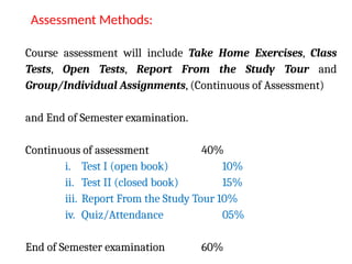
Course assessment willinclude Take Home Exercises, Class
Tests, Open Tests, Report From the Study Tour and
Group/Individual Assignments, (Continuous of Assessment)
and End of Semester examination.
Continuous of assessment 40%
i. Test I (open book) 10%
ii. Test II (closed book) 15%
iii. Report From the Study Tour 10%
iv. Quiz/Attendance 05%
End of Semester examination 60%
Assessment Methods:
Contents
• Basic ideaof protection
• Protective relay
• Nature and causes of faults
– Categories of faults
– Consequences of Faults
– Examples of faults
– Other abnormal conditions
• Components of Substation
– Circuit breakers
– Isolator
– Earthing switch
– Surge arrester
– Current Transformer
– Potential Transformer
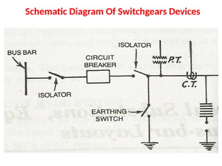
11.
SWITCHGEARS AND POWERPRORECTION :
• Switchgear is a general term covering all
equipment used for Switching, Protection,
Control and Isolation in a power system.
• All equipment used for fault clearing is covered
by the term switchgear.
• Switchgears are used in Generation, Transmission
and Distribution Systems, whereas, Control gears
are used in Consumer Circuits.
12.
Necessity of Switchgears
•Switchgears are necessary at every switching point
in the power system because;
There are several voltage levels and fault levels
which has to be controlled and protected by
accessible switching devices and for isolation, if
the need arises.
Examples of PrincipalSwitchgears:
SWITCHING DEVICES
Circuit Breakers
Isolators (Disconnector or Disconnecting Switch)
Earthing Switches
Load Switches (Ring Main Units)
Contactors
15.
Auxiliary Switchgears
Auxiliary Switchgearsare secondary or subsidiary
equipment which assist the main switchgear
equipment in the control, measurement, protection
and fault-clearing process.
16.
Examples of AuxiliarySwitchgears
PROTECTION DEVICES
–Protection Relays
–Lightning Arresters
–Fuses.
17.
SENSING DEVICES
– Voltage(Potential) Transformers
– Current Transformers
Examples of Auxiliary Switchgears
18.
CONTROL (COMPENSATION) DEVICES
–Series Inductive Reactors
– Shunt Inductive Reactors
– Series Capacitive Reactors
– Shunt Capacitive Reactors
Examples of Auxiliary Switchgears
19.
AUXILIARY POWER SUPPLYDEVICES
• Tripping Units (Battery Bank & Charger)
Examples of Auxiliary Switchgears
20.
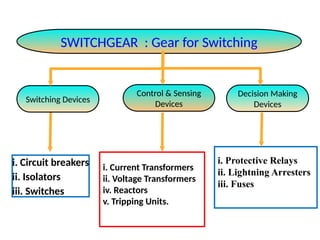
Switch gear -It's function
SWITCHGEAR : Gear for Switching
Switching Devices
Control & Sensing
Devices
Decision Making
Devices
i. Circuit breakers
ii. Isolators
iii. Switches
i. Current Transformers
ii. Voltage Transformers
iv. Reactors
v. Tripping Units.
i. Protective Relays
ii. Lightning Arresters
iii. Fuses
Basic Idea ofProtection
• The principle function of Electric power system
(PS) is to ensure the availability of electrical
energy without interruption.
• However, PS extends to several thousand of kms.
• Most of lines are overhead so they are exposed
to risks of damage or breakdown
–Eg. Storm, falling objects, damage to insulators
etc…
• These can interrupt the power availability to the
loads
• So protection is needed
23.
Protective Relay
• Protectiverelay and relaying system detects abnormal
conditions like faults in electrical circuits and operates
automatic switch gear to isolate faulty equipment from
the system as quick as possible.
• This limits the damage at the fault location and
prevents the effects of the fault spreading into the
system
• Protective relay must be able to recognize abnormal
conditions and take suitable steps to ensure its
removal with the least possible disturbance to normal
operation.
24.
Categories of Faults
(a)Breakdown at normal operating voltage
– Deterioration of the insulation
– Damage due to unpredictable causes such accidental
short circuiting by snakes, kite strings, tree branches
(b) Breakdown due to abnormal voltages though the
insulation is healthy to withstand normal voltage
This may happen due to:
– Switching surges
– Surges caused by lighting
25.
Nature and Causesof Faults
• The nature of fault simply implies any
abnormal conditions which causes a reduction
in the basic insulation strength,
i. Between phase conductors,
ii. Between phase conductors and earth,
iii. Or any earthed screens surrounding the
conductors
26.
Examples of Faults
i.Single line to ground fault
ii. Double line to ground fault
iii.Three phase to ground fault
iv. Line to line fault
v. Open circuit fault
27.
Other Abnormal Conditions
Voltage and current unbalance (loose connect, worn contacts,
load distribution)
Under/over frequency (full or partial load rejection or overloading)
Under/over voltages (short circuit fault on single phase or all 3
phases )
Temperature rise (short circuit or spark-gap or lack of proper
heat dissipation)
Reversal of power (insufficient power flowing in to a prime
mover (motoring action))
Power swings (caused by large disturbances in the power
system, if not blocked can cause wrong operation of distance relay
and wrong tripping of transmission line cct breaker)
28.
Consequences of Faults
i.Great reduction of the line voltage over a major
part of the power system.
ii. Damage to the elements of the system by the
electrical arc associated to the short circuit.
iii. Damage to other apparatus in the system due to
overheating and abnormal mechanical forces.
iv. Disturbances to the stability of the electrical
system.
v. Reduction in the voltage of the system.
29.
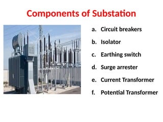
Components of Substation
a.Circuit breakers
b. Isolator
c. Earthing switch
d. Surge arrester
e. Current Transformer
f. Potential Transformer
30.
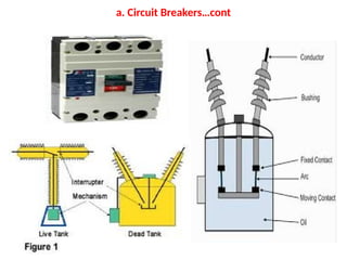
a. Circuit Breakers
•A circuit breaker is an automatically
operated electrical switch designed to protect an
electrical circuit from damage caused
by overload or short-circuit.
• Its basic function is
i. To detect a fault condition signal and interrupt
current flow.
ii. Switching during normal and abnormal
conditions, interrupt the fault currents.
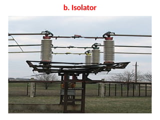
• A disconnector,Disconnect switch or Isolator
switch is used to ensure that an electrical circuit
is completely de-energised for service or
maintenance.
• Such switches are often found in electrical
distribution and industrial applications, where
machinery must have its source of driving power
removed for adjustment or repair.
b. Isolator…cont
34.
• High-voltage isolationswitches are used in
electrical substations to allow isolation of
apparatus such as circuit breakers,
transformers and transmission lines, for
maintenance.
• The disconnector is usually not intended for
normal control of the circuit, but only for safety
isolation.
• Disconnector can be operated either manually
or automatically (motorized disconnector).
b. Isolator…cont
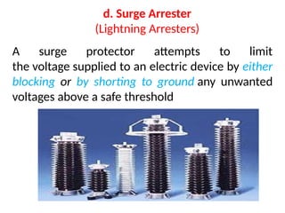
d. Surge Arrester
(LightningArresters)
A surge protector attempts to limit
the voltage supplied to an electric device by either
blocking or by shorting to ground any unwanted
voltages above a safe threshold
38.
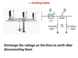
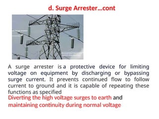
Diverting the highvoltage surges to earth and
maintaining continuity during normal voltage
d. Surge Arrester…cont
A surge arrester is a protective device for limiting
voltage on equipment by discharging or bypassing
surge current. It prevents continued flow to follow
current to ground and it is capable of repeating these
functions as specified
39.
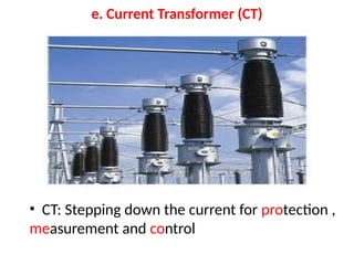
e. Current Transformer(CT)
• CT: Stepping down the current for protection ,
measurement and control