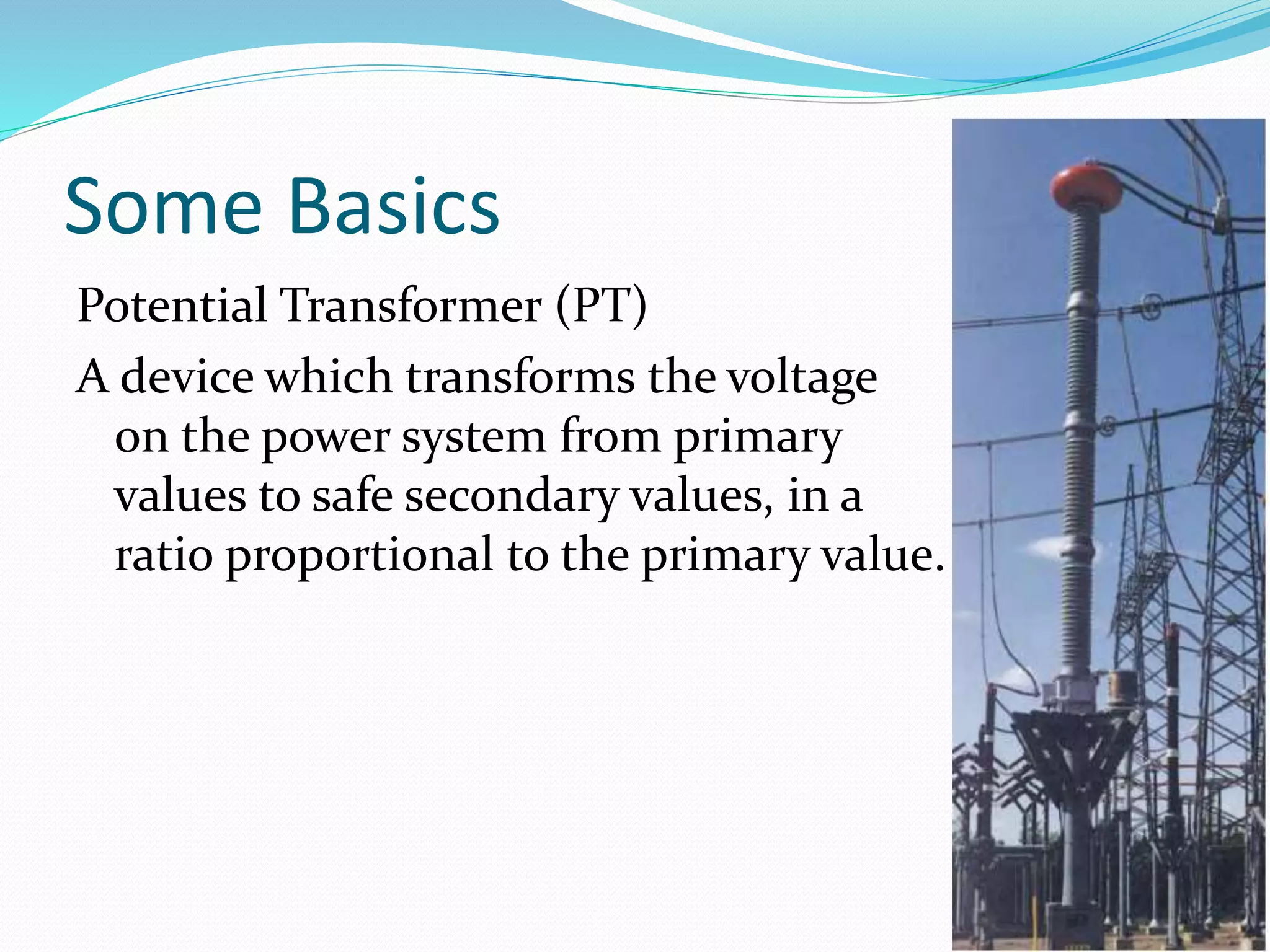
NATIONAL CONFERENCE ON RECENT TRENDS AND
INNOVATION IN SCIENCE, TECHNOLOGY &
MANAGEMENT
POWER SYSTEM PROTECTOIN TECHNIQUE : A REVIEW
Presented By
Sahid Raja Khan (EE VI sem)
Compucom Institute Of Technology & Management, Jaipur
What is system protection ?
 System protection is the art and science of detecting
problems with power system components and
isolating these components.
 Problems on the power system include:
1. Short circuit
2. Abnormal conditions
3. Equipment failures
Features of a Protection System
 Speed
 Reliability
 Security
 Sensitivity
 Economy
Purpose of system protection
 Protect the public
 Improve system stability
 Minimize damage to equipment
 Protect against overloads
 employ relay techs and engineers
What component (Equipment) do we protect ?
 Alternators
 Transformers
 Transmission lines
 Bus bars
 Distribution Lines
 Feeders
 Consumer Lines
 Synchronous Motors
What component (Equipment) do we protect ?
Some Basics
Protective relays monitor the current and/or voltage of
the power system to detect problems with the power
system. Currents and voltages to relays are supplied via
CT’s and PT’s.
Some Basics
Current Transformer (CT)
A device which transform the current on the power
system from large primary values to safe secondary
values. The secondary current will be proportional (as
per the ratio) to the primary current.
Some Basics
Potential Transformer (PT)
A device which transforms the voltage
on the power system from primary
values to safe secondary values, in a
ratio proportional to the primary value.
I. Generator Protection
What can go wrong ?
A. Stator winding Problem
1. Winding-winding short
2. Stator Ground
Generator protection
How do we protect the stator?
A. Differential Protection (what goes in must come out)
1. Detects phase-phase faults
B. Stator ground protection
1. Third Harmonic Voltage Method (100% of stator)
2. Signal Injection (100% of Stator)
Generator protection
What can go wrong ?
B. Rotor Problems
1. Loss of field
2. Field ground
a. First ground
b. Second ground
Generator protection
How do we protect the rotor?
1. Loss of field
a. Impedance
2. Field ground
a. DC voltage relay
The field ground relay is connected from the negative side
of the field to DC ground. Detects voltage from the field to
ground.
Generator protection
What else can go wrong?
C. Abnormal Conditions
1. Over/Under Frequency
2. Over Excitation
3. Reverse Power
4. Out of Step
5. Unbalance Current
Transformer Protection
Power Transformers are expensive and are a long-lead-
time item. So protection must be effective.
Transformer Protection
What can go wrong?
• Winding-to-winding faults
• Winding-to-ground faults
• Bushing faults
Transformer Protection
Protection Methods
• Fuse
• Over-current
• Differential
Transmission Line Protection
Transmission lines can vary in length from several hundred
feet to several hundred miles, and in voltage (line-to-line)
from 46kv to 750kv.
construction can be simple, such as a single wood pole with
insulators atop a cross-arm, with little spacing between the
conductors and from conductors to ground. At the other
end of the scale are metal lattice structures with bundled
conductors (2 or more conductors per phase) with large
spacing between conductors and between conductors and
ground.
Transmission Line Protection
What can go wrong?
FAULTS (Short Circuits)
Some causes of faults:
• trees
• Lightening
• Animals (Birds, Squirrels, Snakes)
• Weather (wind, snow, ice)
• Natural disasters (earthquakes, floods)
• Faulty equipment (switches, insulators, clamps, etc.)
Transmission Line Protection
Faults
“ Faults come uninvited and seldom go away voluntarily.”
Fault Types:
 Single line-to-ground
 Line-to-line
 three phase
 Line-to-line-to-ground
Transmission Line Protection
How do we protect Transmission Lines?
A. Over-current
B. Directional Over-current
C. Distance (Impedance)
D. Pilot
E. Line Current Differential
Power System Protection Technique: A Review

Power System Protection Technique: A Review

  • 1.
    NATIONAL CONFERENCE ONRECENT TRENDS AND INNOVATION IN SCIENCE, TECHNOLOGY & MANAGEMENT POWER SYSTEM PROTECTOIN TECHNIQUE : A REVIEW Presented By Sahid Raja Khan (EE VI sem) Compucom Institute Of Technology & Management, Jaipur
  • 2.
    What is systemprotection ?  System protection is the art and science of detecting problems with power system components and isolating these components.  Problems on the power system include: 1. Short circuit 2. Abnormal conditions 3. Equipment failures
  • 3.
    Features of aProtection System  Speed  Reliability  Security  Sensitivity  Economy
  • 4.
    Purpose of systemprotection  Protect the public  Improve system stability  Minimize damage to equipment  Protect against overloads  employ relay techs and engineers
  • 5.
    What component (Equipment)do we protect ?  Alternators  Transformers  Transmission lines  Bus bars  Distribution Lines  Feeders  Consumer Lines  Synchronous Motors
  • 6.
  • 7.
    Some Basics Protective relaysmonitor the current and/or voltage of the power system to detect problems with the power system. Currents and voltages to relays are supplied via CT’s and PT’s.
  • 8.
    Some Basics Current Transformer(CT) A device which transform the current on the power system from large primary values to safe secondary values. The secondary current will be proportional (as per the ratio) to the primary current.
  • 9.
    Some Basics Potential Transformer(PT) A device which transforms the voltage on the power system from primary values to safe secondary values, in a ratio proportional to the primary value.
  • 10.
    I. Generator Protection Whatcan go wrong ? A. Stator winding Problem 1. Winding-winding short 2. Stator Ground
  • 11.
    Generator protection How dowe protect the stator? A. Differential Protection (what goes in must come out) 1. Detects phase-phase faults B. Stator ground protection 1. Third Harmonic Voltage Method (100% of stator) 2. Signal Injection (100% of Stator)
  • 12.
    Generator protection What cango wrong ? B. Rotor Problems 1. Loss of field 2. Field ground a. First ground b. Second ground
  • 13.
    Generator protection How dowe protect the rotor? 1. Loss of field a. Impedance 2. Field ground a. DC voltage relay The field ground relay is connected from the negative side of the field to DC ground. Detects voltage from the field to ground.
  • 14.
    Generator protection What elsecan go wrong? C. Abnormal Conditions 1. Over/Under Frequency 2. Over Excitation 3. Reverse Power 4. Out of Step 5. Unbalance Current
  • 15.
    Transformer Protection Power Transformersare expensive and are a long-lead- time item. So protection must be effective.
  • 16.
    Transformer Protection What cango wrong? • Winding-to-winding faults • Winding-to-ground faults • Bushing faults
  • 17.
    Transformer Protection Protection Methods •Fuse • Over-current • Differential
  • 18.
  • 19.
    Transmission Line Protection Transmissionlines can vary in length from several hundred feet to several hundred miles, and in voltage (line-to-line) from 46kv to 750kv. construction can be simple, such as a single wood pole with insulators atop a cross-arm, with little spacing between the conductors and from conductors to ground. At the other end of the scale are metal lattice structures with bundled conductors (2 or more conductors per phase) with large spacing between conductors and between conductors and ground.
  • 20.
  • 21.
    Transmission Line Protection Whatcan go wrong? FAULTS (Short Circuits) Some causes of faults: • trees • Lightening • Animals (Birds, Squirrels, Snakes) • Weather (wind, snow, ice) • Natural disasters (earthquakes, floods) • Faulty equipment (switches, insulators, clamps, etc.)
  • 22.
    Transmission Line Protection Faults “Faults come uninvited and seldom go away voluntarily.” Fault Types:  Single line-to-ground  Line-to-line  three phase  Line-to-line-to-ground
  • 23.
    Transmission Line Protection Howdo we protect Transmission Lines? A. Over-current B. Directional Over-current C. Distance (Impedance) D. Pilot E. Line Current Differential