Download as PDF, PPTX

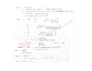


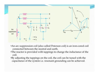
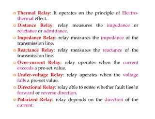
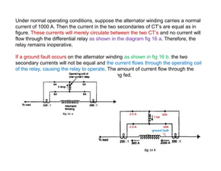
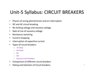
![• Suppose line to ground fault occurs in the line B at point
F. The fault current IF and capacitive currents IR and IY will
flow as shown in Fig
• Note that IF flows through the Peterson coil (or Arc
suppression coil) to neutral and back through the fault. The
total capacitive current IC is the phasor sum of IR & IY
as shown in phasor diagram in Fig.
• The voltage of the faulty phase is applied across the arc
suppression coil. Therefore, fault current IF lags the faulty
phase voltage by 90°.
• The current IF is in phase opposition to capacitive
current IC [See Fig].
By adjusting the tappings on the Peterson coil, the
resultant current in the fault can be reduced. If inductance
of the coil is so adjusted that IL= IC , then resultant current
in the fault will be zero.
• Suppose line to ground fault occurs in the line B at point
F. The fault current IF and capacitive currents IR and IY will
flow as shown in Fig
• Note that IF flows through the Peterson coil (or Arc
suppression coil) to neutral and back through the fault. The
total capacitive current IC is the phasor sum of IR & IY
as shown in phasor diagram in Fig.
• The voltage of the faulty phase is applied across the arc
suppression coil. Therefore, fault current IF lags the faulty
phase voltage by 90°.
• The current IF is in phase opposition to capacitive
current IC [See Fig].
By adjusting the tappings on the Peterson coil, the
resultant current in the fault can be reduced. If inductance
of the coil is so adjusted that IL= IC , then resultant current
in the fault will be zero.](https://image.slidesharecdn.com/ee6702-psglecturenotesr2013-160701041316/85/EE6702-Protection-and-Switchgear-notes-R2013-84-320.jpg)

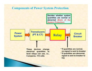


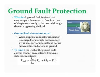


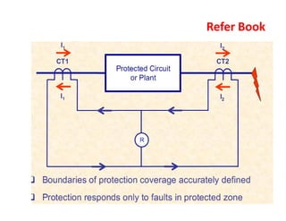

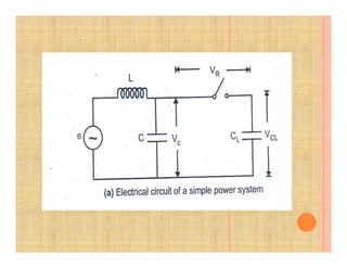

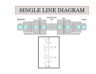
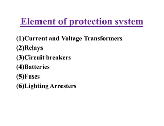
This document provides an overview of protection and switchgear for an electrical engineering course. It includes definitions of key components in a power system like transformers, circuit breakers, and protective relays. It also describes the purpose of a protection system to isolate faults and prevent equipment damage. Additional sections cover current and voltage transformers, batteries, fuses, lighting arresters, and the different categories and functions of switchgear.


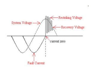
![protection of transmission lines[distance relay protection scheme]](https://cdn.slidesharecdn.com/ss_thumbnails/os-exe3-23-may2011-sr-i-776s21tr-lineprotection-120425095503-phpapp02-thumbnail.jpg?width=640&height=640&fit=bounds)