Downloaded 895 times


![29
GE Consumer & Industrial
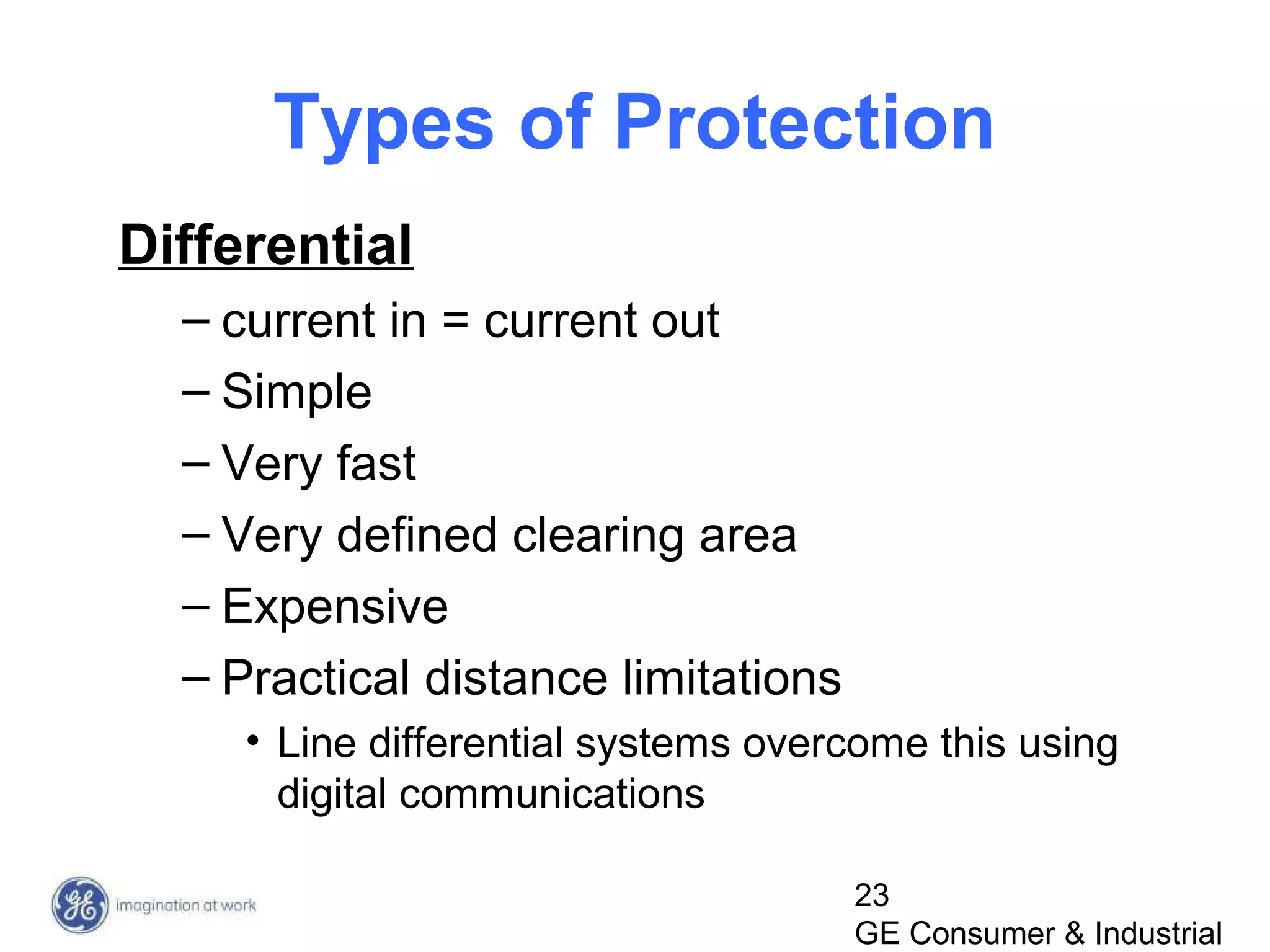
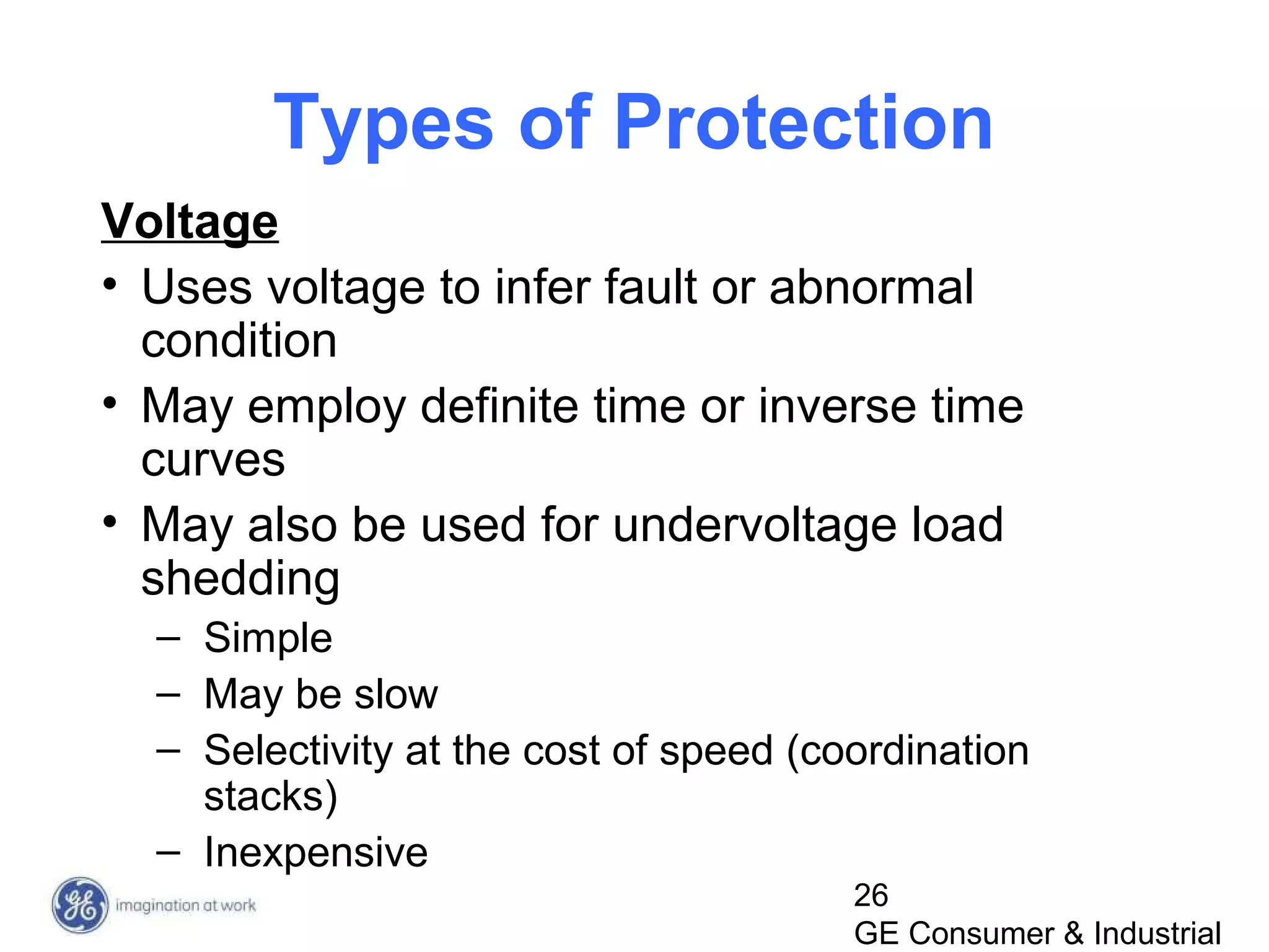
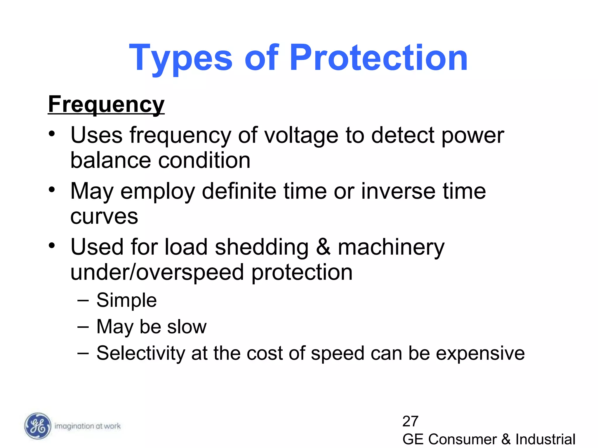
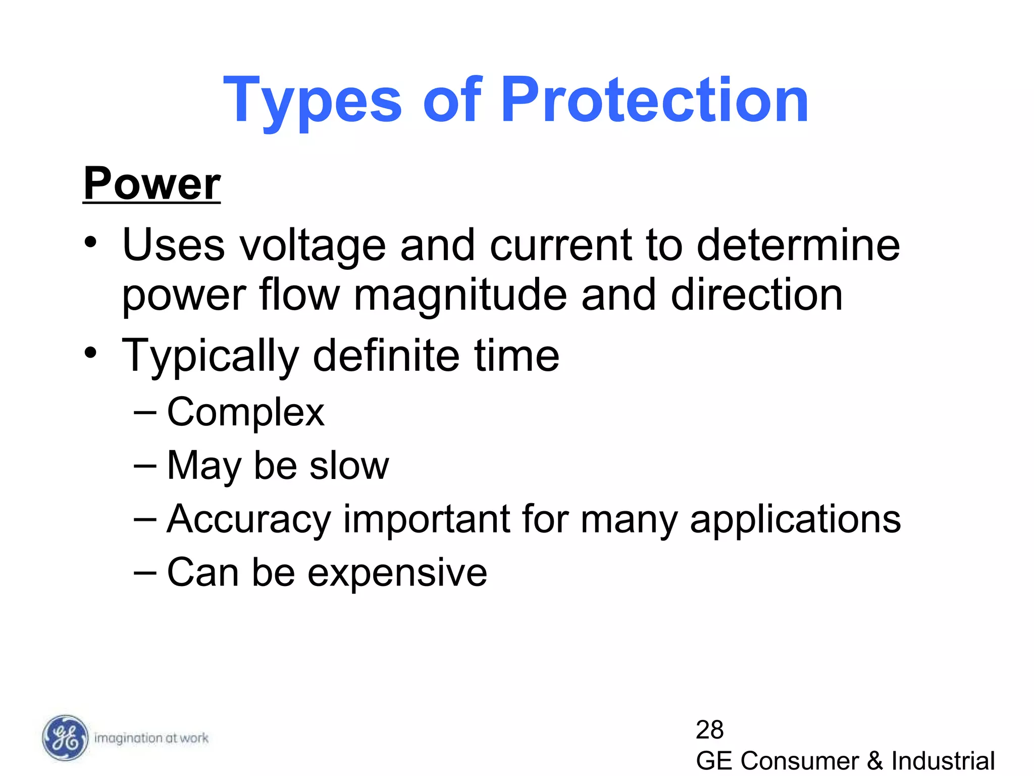
Types of Protection
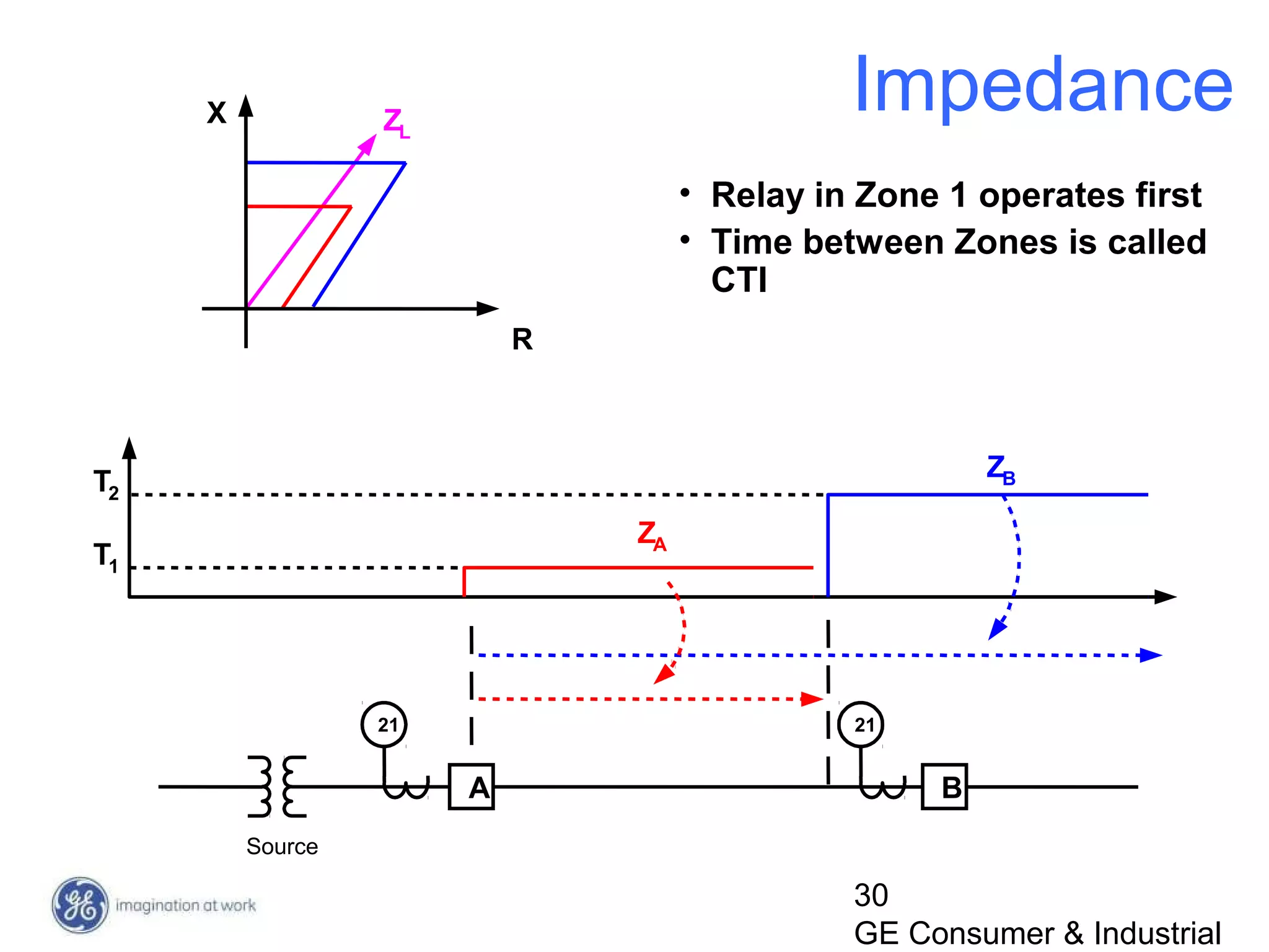
Distance (Impedance)
– Uses voltage and current to determine impedance of
fault
– Set on impedance [R-X] plane
– Uses definite time
– Impedance related to distance from relay
– Complicated
– Fast
– Somewhat defined clearing area with reasonable
accuracy
– Expensive
– Communication aided schemes make more selective](https://image.slidesharecdn.com/protectionbasicsr2-150208112924-conversion-gate02/75/Power-System-Protection-basics-28-2048.jpg)
![43
GE Consumer & Industrial
1-Line Symbols [1]](https://image.slidesharecdn.com/protectionbasicsr2-150208112924-conversion-gate02/75/Power-System-Protection-basics-36-2048.jpg)
![44
GE Consumer & Industrial
1-Line Symbols [2]](https://image.slidesharecdn.com/protectionbasicsr2-150208112924-conversion-gate02/75/Power-System-Protection-basics-37-2048.jpg)
![45
GE Consumer & Industrial
1-Line Symbols [3]](https://image.slidesharecdn.com/protectionbasicsr2-150208112924-conversion-gate02/75/Power-System-Protection-basics-38-2048.jpg)
![46
GE Consumer & Industrial
1-Line Symbols [4]](https://image.slidesharecdn.com/protectionbasicsr2-150208112924-conversion-gate02/75/Power-System-Protection-basics-39-2048.jpg)
![47
GE Consumer & Industrial
1-Line [1]](https://image.slidesharecdn.com/protectionbasicsr2-150208112924-conversion-gate02/75/Power-System-Protection-basics-40-2048.jpg)
![1-Line [2]](https://image.slidesharecdn.com/protectionbasicsr2-150208112924-conversion-gate02/75/Power-System-Protection-basics-41-2048.jpg)


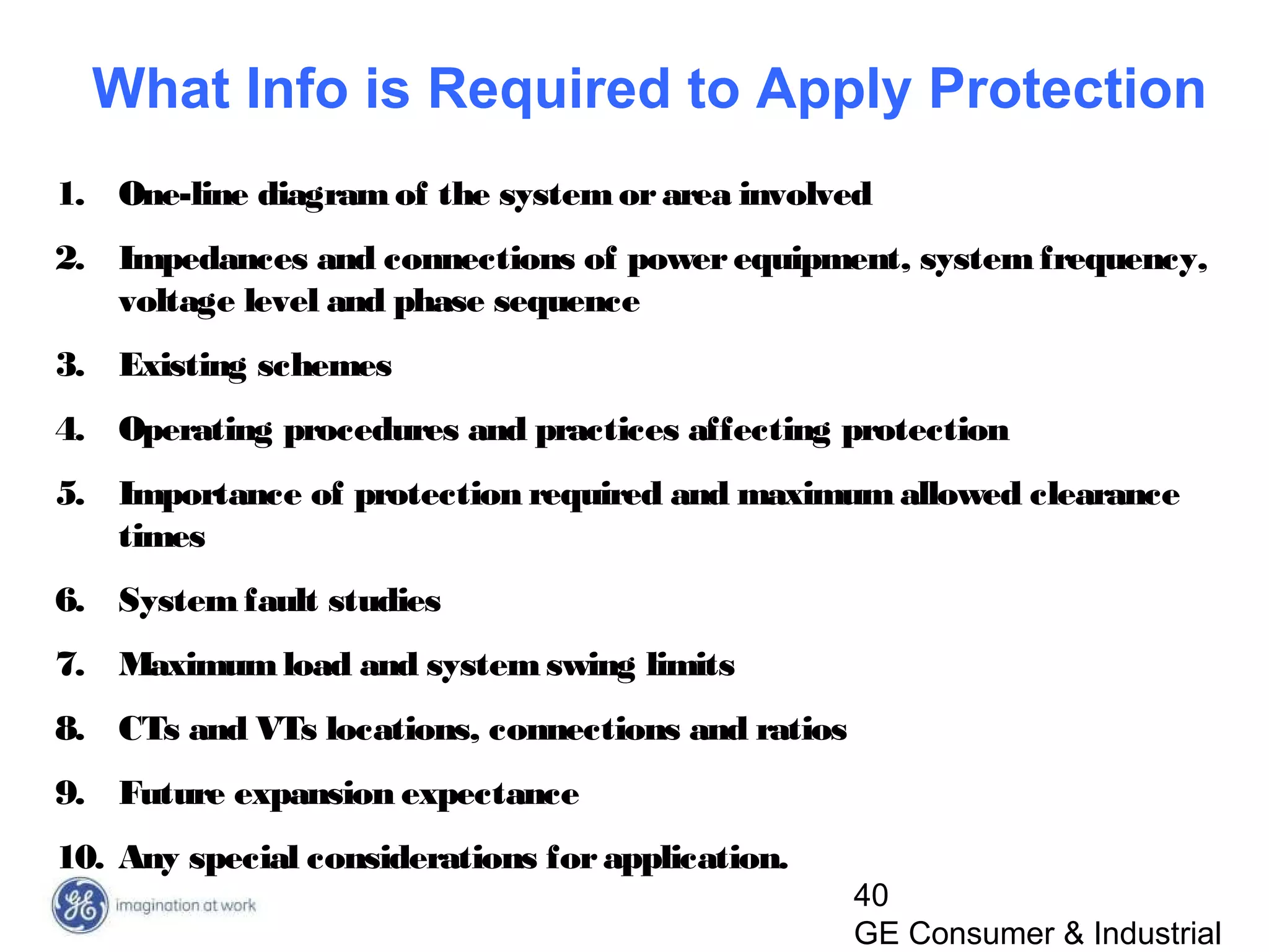
This document provides an overview of a training session on protection fundamentals presented by Craig Wester and John Levine of GE Multilin. The training covers protection tools, demonstration relays, future training classes, and protection fundamentals. The fundamentals section discusses desirable protection attributes, selection of protective relays, primary equipment components, and various types of protection including overcurrent, differential, voltage, frequency, power, and distance protection. Information required for applying protection is also listed.


![protection of transmission lines[distance relay protection scheme]](https://cdn.slidesharecdn.com/ss_thumbnails/os-exe3-23-may2011-sr-i-776s21tr-lineprotection-120425095503-phpapp02-thumbnail.jpg?width=640&height=640&fit=bounds)