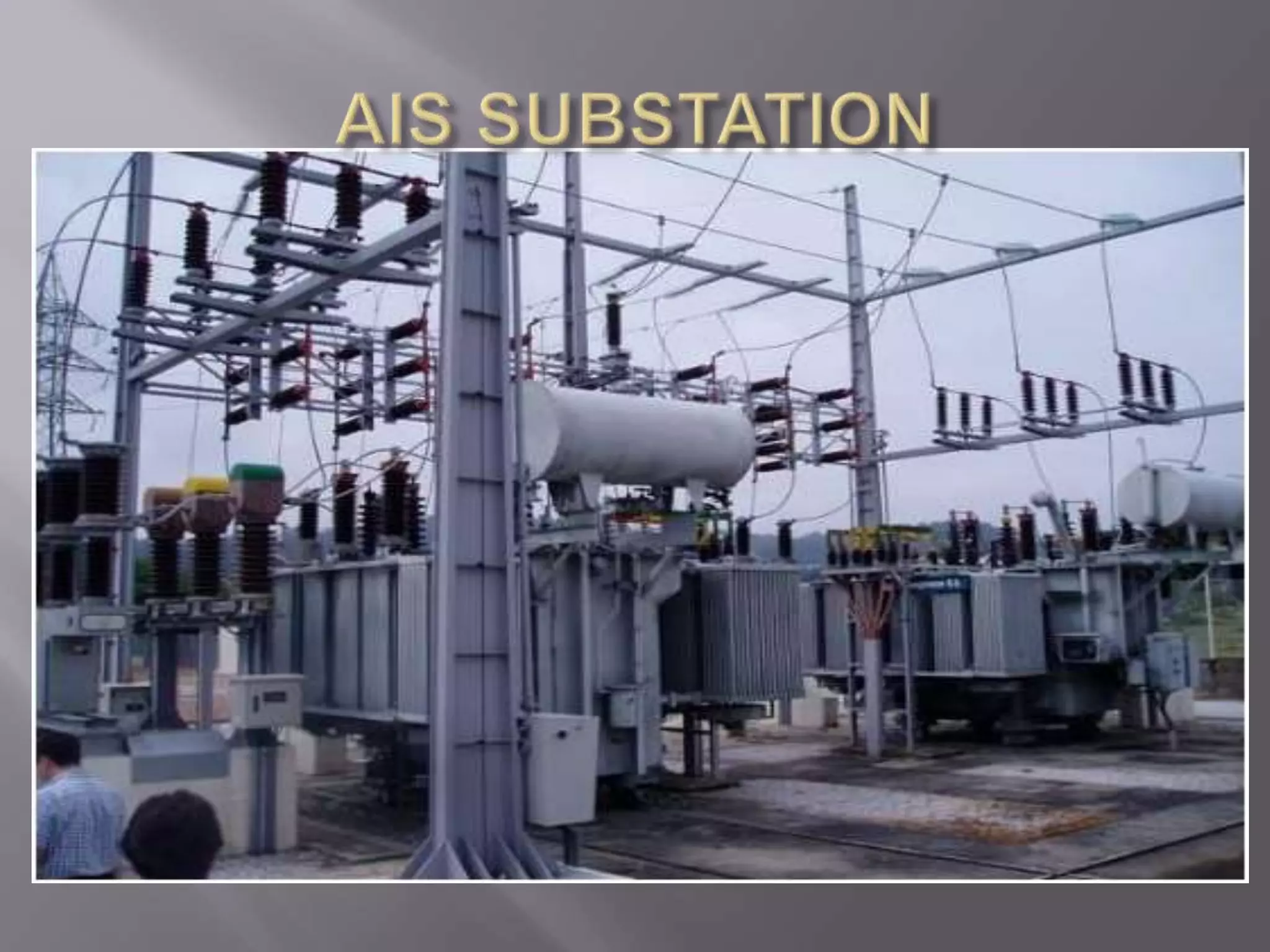
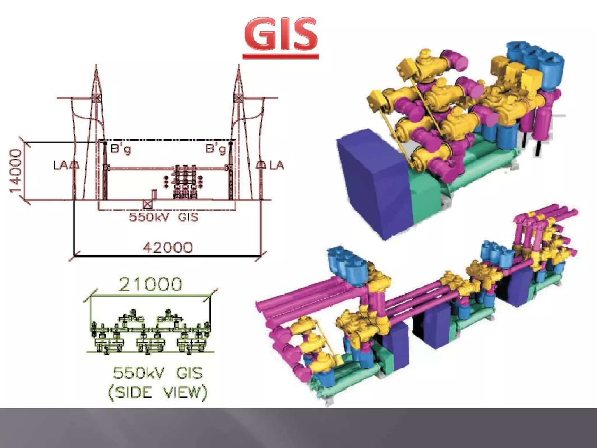
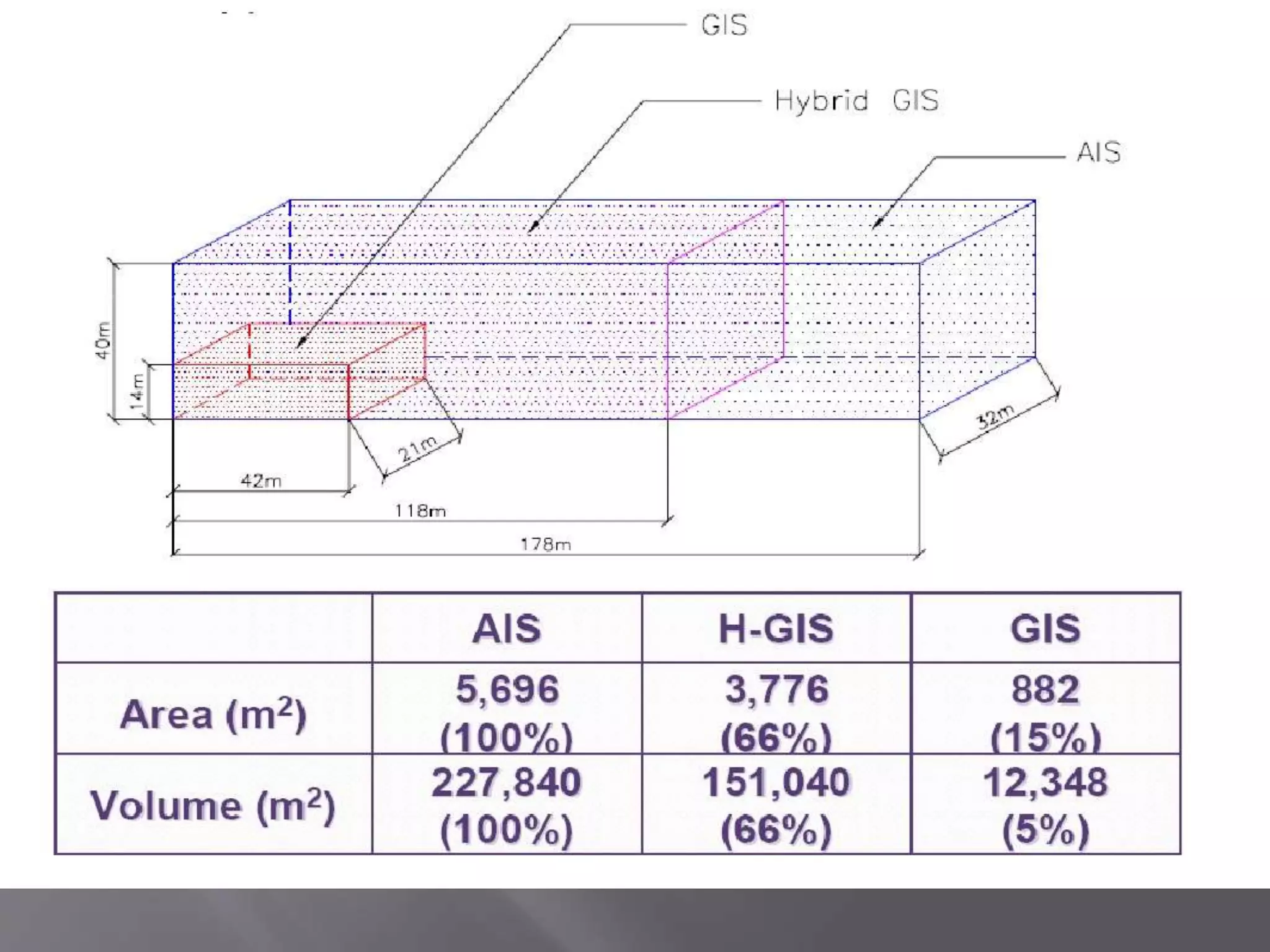
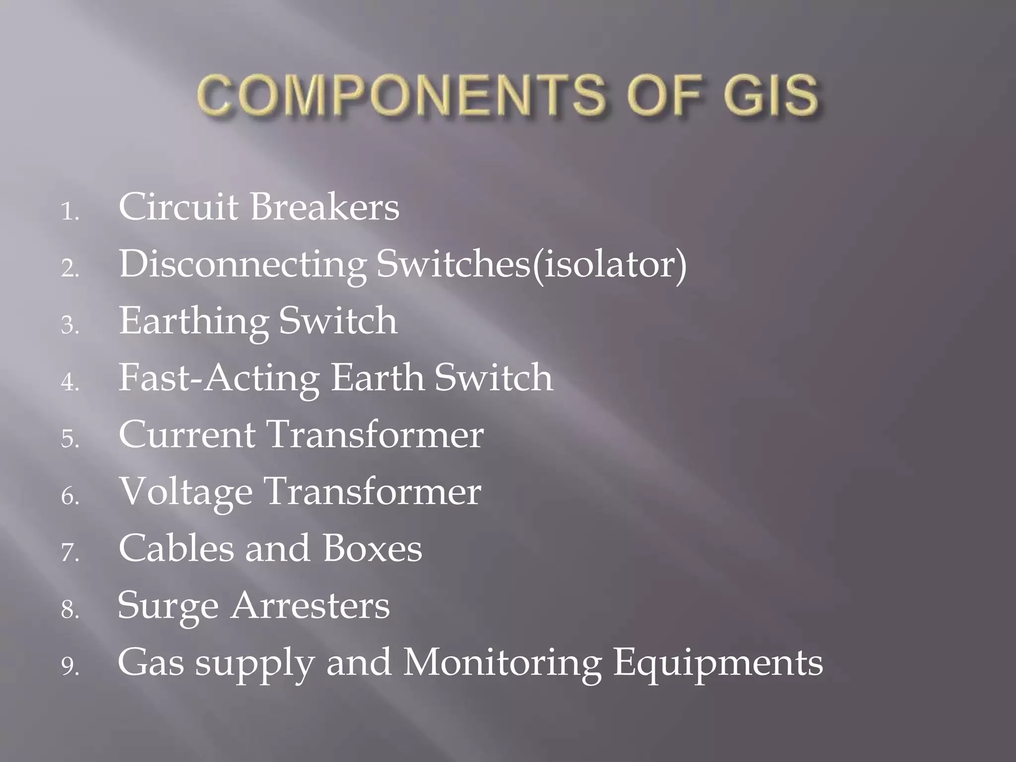
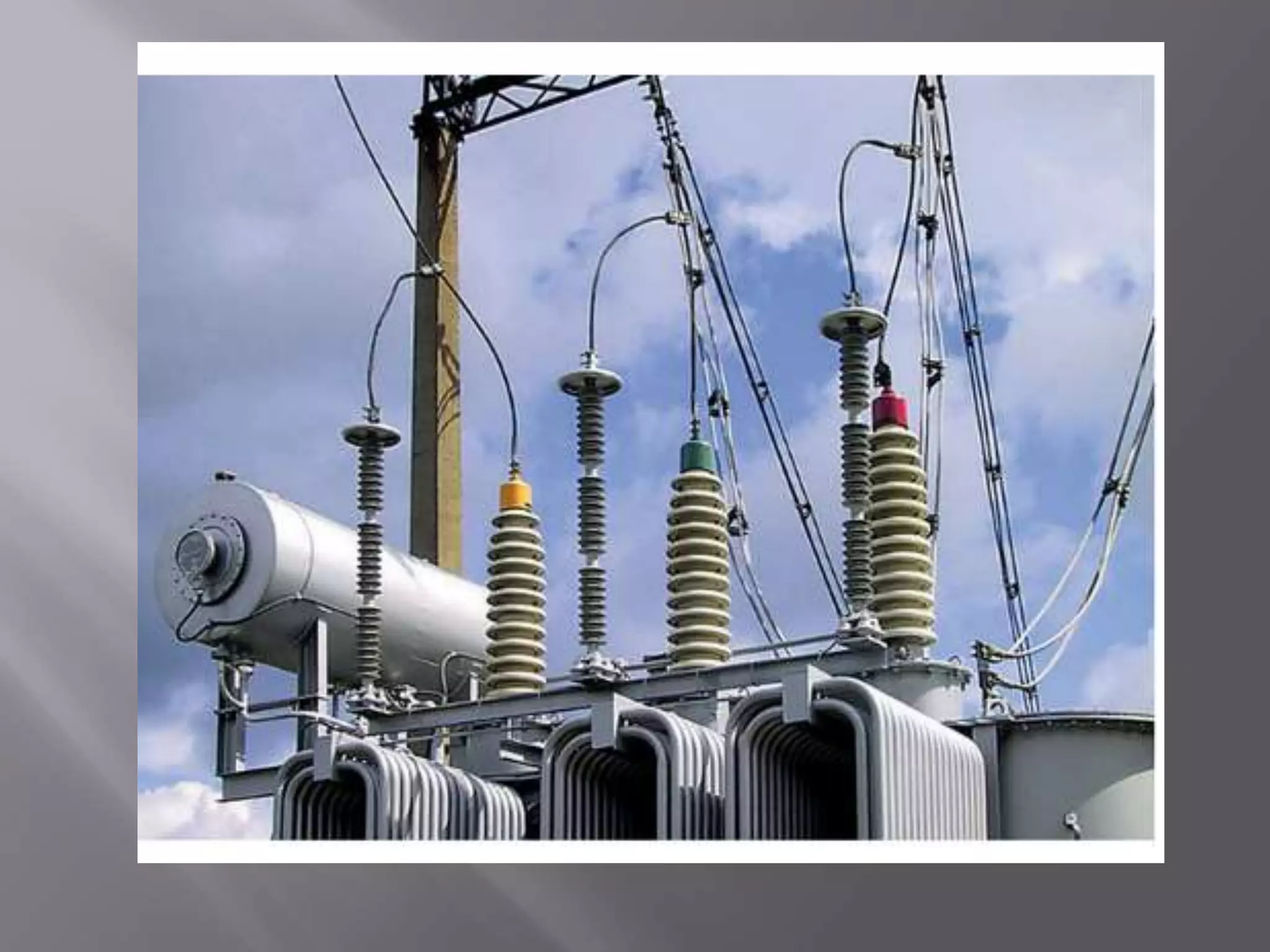
An electrical substation uses components like circuit breakers, busbars, and insulators to control the transmission, transformation, and distribution of power. There are two main types of substation insulation systems: air insulated (AIS) and gas insulated (GIS). AIS uses air as insulation between live components, while GIS uses sulfur hexafluoride gas to insulate live components within a sealed metal enclosure. GIS systems require less space than AIS but have higher installation costs. Protective devices in substations include circuit breakers, disconnectors, earthing switches, and surge arresters, which work to isolate faulty sections of the electrical network to prevent damage.
The document outlines various components of a power system protection system. It discusses the need for protection to maintain reliable power supply and minimize equipment damage. The key elements to be protected include generators, transformers, transmission lines, and busbars. Protection schemes for each element are then described, such as differential protection for generators and transformers, Buchholz relays for transformers, and distance and line differential protection for transmission lines.
This document provides an overview of the EE2402 Protection & Switchgear course presented by C.Gokul. It includes the course syllabus, units covered, textbook references and introductory content on power system basics, components, faults, protection elements, relay terminology and essential qualities of protection systems. The key topics discussed are types of faults in power systems, importance of protective schemes, elements of a protection system including current transformers, voltage transformers, relays and circuit breakers. Neutral earthing methods with a focus on Peterson coil are also introduced.
The document discusses power system protection and protective relays. It provides definitions of key terms like protection, relay, circuit breaker. It describes the basic components of a protection system including transducers, relays, tripping mechanisms, and circuit breakers. It also summarizes the main types of faults that can occur in a power system like short circuits and abnormalities. Additionally, it discusses the desirable characteristics of protective relays like speed, security, dependability, and selectivity. The document covers different classifications of relays according to their construction, incoming signals, and the type of protection provided. It also describes various types of electromagnetic relays specifically attracted armature and plunger relays.
Power System protection and Metering,Types of Faults and effects,Symmetrical faults,Unsymmetrical faults,Fault Statics,Components of power System protection,Relay,Classification of Relay,Induction relay,thermal relay,Static Relay,Numerical Relay
This presentation described in a National Level Conference in CITM College Jaipur named as POWER SYSTEM PROTECTION TECHNIQUE: A REVIEW. This was presented by Sahid Raja Khan B.Tech. (Electrical Engineering) Hons.
FUNDAMENTALS OF POWER SYSTEM PROTECTION
FUNDAMENTALS OF POWER SYSTEM PROTECTIONFUNDAMENTALS OF POWER SYSTEM PROTECTIONFUNDAMENTALS OF POWER SYSTEM PROTECTIONFUNDAMENTALS OF POWER SYSTEM PROTECTIONFUNDAMENTALS OF POWER SYSTEM PROTECTIONFUNDAMENTALS OF POWER SYSTEM PROTECTIONFUNDAMENTALS OF POWER SYSTEM PROTECTIONFUNDAMENTALS OF POWER SYSTEM PROTECTIONFUNDAMENTALS OF POWER SYSTEM PROTECTIONFUNDAMENTALS OF POWER SYSTEM PROTECTIONFUNDAMENTALS OF POWER SYSTEM PROTECTIONFUNDAMENTALS OF POWER SYSTEM PROTECTIONFUNDAMENTALS OF POWER SYSTEM PROTECTIONFUNDAMENTALS OF POWER SYSTEM PROTECTIONFUNDAMENTALS OF POWER SYSTEM PROTECTIONFUNDAMENTALS OF POWER SYSTEM PROTECTIONFUNDAMENTALS OF POWER SYSTEM PROTECTIONFUNDAMENTALS OF POWER SYSTEM PROTECTIONFUNDAMENTALS OF POWER SYSTEM PROTECTIONFUNDAMENTALS OF POWER SYSTEM PROTECTIONFUNDAMENTALS OF POWER SYSTEM PROTECTIONFUNDAMENTALS OF POWER SYSTEM PROTECTIONFUNDAMENTALS OF POWER SYSTEM PROTECTIONFUNDAMENTALS OF POWER SYSTEM PROTECTIONFUNDAMENTALS OF POWER SYSTEM PROTECTIONFUNDAMENTALS OF POWER SYSTEM PROTECTIONFUNDAMENTALS OF POWER SYSTEM PROTECTIONFUNDAMENTALS OF POWER SYSTEM PROTECTIONFUNDAMENTALS OF POWER SYSTEM PROTECTIONFUNDAMENTALS OF POWER SYSTEM PROTECTIONFUNDAMENTALS OF POWER SYSTEM PROTECTIONFUNDAMENTALS OF POWER SYSTEM PROTECTIONFUNDAMENTALS OF POWER SYSTEM PROTECTIONFUNDAMENTALS OF POWER SYSTEM PROTECTIONFUNDAMENTALS OF POWER SYSTEM PROTECTIONFUNDAMENTALS OF POWER SYSTEM PROTECTIONFUNDAMENTALS OF POWER SYSTEM PROTECTIONFUNDAMENTALS OF POWER SYSTEM PROTECTIONFUNDAMENTALS OF POWER SYSTEM PROTECTIONFUNDAMENTALS OF POWER SYSTEM PROTECTIONFUNDAMENTALS OF POWER SYSTEM PROTECTIONFUNDAMENTALS OF POWER SYSTEM PROTECTIONFUNDAMENTALS OF POWER SYSTEM PROTECTIONFUNDAMENTALS OF POWER SYSTEM PROTECTIONFUNDAMENTALS OF POWER SYSTEM PROTECTIONFUNDAMENTALS OF POWER SYSTEM PROTECTIONFUNDAMENTALS OF POWER SYSTEM PROTECTION
This document is a student's final report on testing the earthing system of a 10 MVA power transformer at a substation in Palembang, Indonesia. The student defines a final report and the purpose of their report. The background discusses how electricity usage is increasing with technology, requiring reliable distribution systems. Earthing systems are important for protecting equipment from short circuits and leakage currents. The objectives are to determine the electrode type used and grounding impedance. Benefits include preventing disturbances, maintaining power distribution, and protecting workers from electrical shock. The student thanks the reader for their attention.
This document discusses power system protection settings. It begins by introducing the functions of protective relays and the information needed to calculate settings, such as line parameters, transformer parameters, fault studies results, and CT and VT ratios. It then describes the protection settings process and functional elements of protective relays. The document discusses the operating characteristics of overcurrent, directional, and distance protection elements. It explains concepts like current grading, time grading, and directional elements as they relate to achieving selectivity in protection schemes. Finally, it provides more details on distance protection principles and operating characteristics.
This document provides an overview of the course EEE 6903: Advanced Protective Relays. It discusses the contents of the course, which includes reviewing different types of relays and their principles of operation, the effects of transients on relays, harmonic relaying, and applications of static and digital relays. It also provides background on power systems, the need for protective relays, common faults in power systems, and desirable qualities for protective relays such as selectivity, speed, sensitivity, reliability and economy. Key terms related to protective relaying are defined.
The document discusses power system protection methods. It explains that protection schemes aim to isolate only faulted parts of the electrical network while keeping the rest operational. Protection systems typically include current and voltage transformers, protective relays, circuit breakers, and batteries. Relays sense faults and trigger circuit breakers to disconnect the faulty section. Fuses also provide protection for some distribution systems. The objective is to protect assets and ensure continuous energy supply.
Switchgears play a vital role in modern power systems, protecting electrical circuits from generation through transmission to distribution. Switchgears include circuit breakers, current and voltage transformers, protection relays, and other devices. They carry and interrupt normal and fault currents, provide metering and regulation, and clear faults through automatic or manual operation. Switchgears come in various types for different voltage applications, including medium voltage, low voltage, and gas insulated switchgears. Fuses and earth leakage circuit breakers also provide overcurrent protection at the distribution level.
The apparatus used for switching, controlling & protecting the electrical circuits & equipments are known as switchgear.
The switchgear equipments is essentially used with switching & interrupting currents either under normal or abnormal operating condition.
It consists of devices such as switches, fuses, circuit breakers, relays etc.
Basically every electric circuit needs a switching device & a protecting device.
This document contains a presentation given by G Ravindra Kumar about his full semester internship training at GMR Kamalanga Energy Limited. The presentation discusses different types of switchgear including low voltage, medium voltage, and high voltage switchgear. It describes components of switchgear like circuit breakers, relays, current transformers, and details the operating principles and advantages of vacuum and air circuit breakers. Load details of various units of 6.6kV switchgear are also presented.
1) This guide provides information to help design protection systems for electrical power networks. It discusses power system architectures, neutral earthing systems, short circuits, sensors, protection functions, and discrimination techniques.
2) The guide has two parts: the first discusses theoretical aspects of power system studies, while the second provides solutions for protecting different applications such as transformers, motors, and generators.
3) Protection systems aim to safely detect and clear faults while maintaining continuity of power supply. Proper coordination of protection devices is important to isolate only the faulty sections of the network.
Unit I: Introduction to Protection System:
Introduction to protection system and its elements, functions of protective relaying, protective zones, primary and backup protection, desirable qualities of protective relaying, basic terminology.
Relays:
Electromagnetic, attracted and induction type relays, thermal relay, gas actuated relay, design considerations of electromagnetic relay.
Unit-II: Relay Application and Characteristics:
Amplitude and phase comparators, over current relays, directional relays, distance relays, differential relay.
Static Relays: Comparison with electromagnetic relay, classification and their description, over current relays, directional relay, distance relays, differential relay.
Unit-III Protection of Transmission Line:
Over current protection, distance protection, pilot wire protection, carrier current protection, protection of bus, auto re-closing,
Unit-IV: Circuit Breaking:
Properties of arc, arc extinction theories, re-striking voltage transient, current chopping, resistance switching, capacitive current interruption, short line interruption, circuit breaker ratings.
Testing Of Circuit Breaker: Classification, testing station and equipments, testing procedure, direct and indirect testing.
Unit-V Apparatus Protection:
Protection of Transformer, generator and motor.
Circuit Breaker: Operating modes, selection of circuit breakers, constructional features and operation of Bulk Oil, Minimum Oil, Air Blast, SF6, Vacuum and d. c. circuit breakers.
This document discusses protection and relay schemes. It defines relays as electrical switches that open or close circuits under certain conditions. The main relay types are electromagnetic relays, solid-state relays, and microprocessor-based relays. Relays are used to isolate controlling circuits, control high voltage systems with low voltage, and perform logic functions. Protection schemes using relays are needed because electrical systems are not fault-free and faults can damage equipment, so relays help isolate faults. The document covers motor, transformer, and generator protection schemes.
switchgear and protection by vala kamleshKamlesh Vala
Switchgear and protection systems play a vital role in modern power systems. Switchgear includes all switching devices associated with power system protection, control, metering and regulation. The main switching device is the circuit breaker. Circuit breakers can interrupt faults such as single line-to-ground faults, line-to-line faults, double line-to-ground faults, open circuit faults, and three phase faults. Circuit breakers use arc interruption to break current flow during opening of contacts. Common types of circuit breakers include oil, air, SF6, and vacuum circuit breakers. Switchgear equipment like fuses, circuit breakers, isolators, earthing switches, and current/potential transformers serve protection, control
Power System Faults and Protection SystemHarshalJain48
The document discusses various types of faults that can occur in power systems, including symmetrical and unsymmetrical faults. It describes different fault types like line-to-line, line-to-ground, and double line-to-ground faults. Protection devices for power systems are also covered, such as circuit breakers, relays including impedance, distance, and differential relays. Current transformers and potential transformers are explained for their use in protection schemes. Classification of faults by category and probability is presented. Common faults in generators like stator and rotor faults are summarized.
This document provides an overview of power quality standards that relate to protective relaying. It discusses five key standards: IEEE 1159 for power quality monitoring, IEEE 519 for harmonic control, ITIC (CBEMA) curve, IEC 1000-4-7 for harmonics measurements, and EN 50160 for voltage characteristics. The document covers the impact of protective relaying on power quality, the impact of power quality on protective relaying, and the use of power quality monitoring in protective relays. It aims to increase awareness among power and protection engineers of the interrelationships between these topics.
A switchgear or electrical switchgear is a generic term which includes all the switching devices associated with mainly power system protection. It also includes all devices associated with control, metering and regulating of electrical power system. Assembly of such devices in a logical manner forms a switchgear. This is the very basic definition of switchgear.
⋗To get more with details
https://www.youtube.com/channel/UC2SvKI7eepP241VLoui1D5A
The document discusses various protection schemes for generators. It describes (1) differential protection that protects the stator winding from internal faults, (2) rotor earth fault protection that protects the rotor winding, and (3) loss of excitation protection that protects the power system from instability if the generator loses its field excitation. Various other protections discussed include overcurrent, overvoltage, temperature, and reverse power protections. The document provides details on the operating principles and components of these various generator protection schemes.
Reactors are used in power systems to limit fault currents and protect circuit breakers. They function by inserting impedance in a circuit to reduce the magnitude of fault currents. Reactors can be placed in different locations in a power network, including on generators, feeders, bus bars, and tie lines. Their construction involves winding copper cable around a core, with options for air or oil cooling and shielding. Reactors help maintain voltage levels during faults and allow the safe interconnection and addition of new equipment to existing power systems.
Installing, Programming & Commissioning of Power System Protection Relays and...Living Online
The continuity of the electrical power supply is very important to consumers especially in the industrial sector. Protection relays are used in power systems to maximise continuity of supply and are found in both small and large power systems from generation, through transmission, distribution and utilisation of the power. A good understanding of their application, operation and maintenance is critical for operating and maintenance personnel.
In this workshop, you will gain a thorough understanding of the capabilities of power system protection relays and how they fit into the overall distribution network. The practical sessions covering the calculation of fault currents, selection of appropriate relays and relay coordination as well as hands-on practice in configuring and setting of some of the commonly used types of protection relays used in industry will give you an excellent understanding. Simulation software and real relays (but at safe voltages) will be used to give the participants practical experience in setting up and configuring the various power parameters. Both electro-mechanical and microprocessor relays will be used to demonstrate the key configuration settings required and the major differences in the approach adopted between these two classes of relays.
The strengths and weaknesses of the latest microprocessor (or numerical) relays as compared to the older electromechanical relays will be outlined. You will also gain a solid appreciation of how the modern relay communicates not only to the central SCADA system but also between themselves resulting in a truly multifunctional system which includes protection, control and monitoring. Finally, you will gain a solid understanding of issues of reliability and security for the modern relay.
MORE INFORMATION: http://www.idc-online.com/content/installing-programming-and-commissioning-power-system-protection-relays-and-hardware-31
Protection of Transformer
Generator and motor.
Circuit Breaker: Operating modes
Selection of circuit breakers
Constructional features and operation of Bulk Oil,
Minimum Oil,
Air Blast,
SF6,
Vacuum and d. c. circuit breakers.
1. The document discusses protective schemes for electrical power systems. It describes how protective relays and circuit breakers are used to isolate faulty elements of a power system to prevent damage and failure.
2. Faults can occur due to insulation failures or conductor failures and cause issues like equipment damage, fire hazards, voltage reductions, and loss of stability if not cleared quickly.
3. Protective relays monitor current, voltage, phase angle and frequency to detect faults. When a fault is detected, the relays signal circuit breakers to isolate the faulty section within seconds to prevent cascading issues.
This document discusses power system faults and protection. It defines faults as defects in electrical circuits that divert current from its intended path. The most common faults are short circuits caused by insulation or conducting path failures. Switchgear such as circuit breakers, fuses and relays are used to isolate faulty elements and ensure continuity of power supply. Protective relays detect faults using changes in current, voltage, phase angle or frequency and must clear faults within fractions of a second to prevent equipment damage. Common faults include short circuits, over/under voltage/frequency, and overheating.
This document discusses faults in power systems, including types (open circuit and short circuit), causes, and effects. Open circuit faults are caused by failures of conductors and can cause unbalanced voltages and currents. Short circuit faults are caused by insulation failures and result in abnormally high currents, potentially damaging equipment. Faults are classified as symmetrical (all phases shorted simultaneously) or unsymmetrical. Unsymmetrical faults like single line-to-ground are most common. When faults occur, protection devices like circuit breakers and relays quickly isolate the faulty section to prevent damage.
This document discusses various methods of neutral grounding systems for electrical power systems, including their advantages and disadvantages. It describes ungrounded systems, solidly grounded systems, and various resistance grounded systems such as low resistance, high resistance, and resonant grounding. Resistance grounding limits fault currents to reduce equipment damage while still allowing faults to be detected. High resistance grounding further limits currents to below 10 amps, requiring a detection system since faults will not trip breakers. Resonant grounding uses inductive reactance to cancel out the capacitive fault current. Earthing transformers provide an alternative return path for faults on delta windings.
This document provides information about power system protection for a course. It includes:
1. A syllabus covering introduction to protection schemes, operating principles of relays, apparatus protection, circuit interruption theory, and circuit breakers.
2. Details on apparatus protection including considerations for protecting generators, transformers, and transmission lines with zones of protection.
3. An overview of generator protection including faults that can occur and classifications of protective relays into categories based on their response time.
International Journal of Engineering Research and DevelopmentIJERD Editor
Electrical, Electronics and Computer Engineering,
Information Engineering and Technology,
Mechanical, Industrial and Manufacturing Engineering,
Automation and Mechatronics Engineering,
Material and Chemical Engineering,
Civil and Architecture Engineering,
Biotechnology and Bio Engineering,
Environmental Engineering,
Petroleum and Mining Engineering,
Marine and Agriculture engineering,
Aerospace Engineering.
Need for protection
Nature and causes of faults
Types of faults
Fault current calculation using symmetrical components
Zones of protection
Primary and back up protection
Essential qualities of protection
Typical protection schemes.
A fault in a power system is any abnormal condition involving electrical failure of equipment like transformers or generators. There are two main types of faults: open circuit faults caused by a failure of conductors, and short circuit faults resulting from insulation or conducting path failures. Unsymmetrical faults like single-line-to-ground are the most common, accounting for 70-80% of faults, while symmetrical three-phase faults are rare but severe. Faults can be caused by weather, equipment failures, human errors, or fires and can damage equipment if not cleared quickly.
This document provides an introduction and overview of power system protection. It discusses the basic components and concepts of protection systems, including the need for protection, basic requirements, types of faults, protective zones, and primary and backup protection. The key objectives are to safeguard the system, minimize damage from faults, and ensure personnel safety.
Module 1 Power System Protection(18EE72).pptxssuser139a56
This document provides an overview of a course on power system protection. It introduces topics that will be covered, including introduction to power systems, causes and effects of faults, protection schemes, and types of relays. The course textbook is also listed. The document provides definitions of key terms and concepts in power system protection.
Substation design involves considering many factors to ensure safety, reliability, maintainability and the ability to expand the system over time. Key components in a substation include circuit breakers, transformers, busbars, isolators, current and potential transformers, surge arrestors, shunt reactors, and capacitors. The functions of this equipment include switching, voltage transformation, power transfer, protection, insulation and surge protection. Associated systems that support substation function include earthing systems, lighting, protection relays, control cables, and fire suppression systems.
This document provides an introduction to switchgear, including its essential features and components. Switchgear consists of switching and protection devices like circuit breakers, fuses, and relays. It permits switching of electrical equipment under normal operation and detects and isolates faults to protect the system. Key components include switches, fuses, circuit breakers and relays. The document also discusses busbar arrangements, indoor/outdoor accommodation, short circuits and calculating short circuit currents.
The document discusses various power quality problems such as harmonic distortion, voltage sags, swells, and interruptions. It then discusses solutions for power quality problems including maintaining grid adequacy, using distributed resources like distributed generation and energy storage, and implementing enhanced interface devices. The document also describes the operation of the Merus A-series Active Filter, which can be used to compensate for harmonics and reactive power in an electrical system.
1) The document describes the performance of a quadrilateral relay for protection of extra high voltage transmission lines during faults with high resistance.
2) A PSCAD/EMTDC model of a 300km transmission line is developed and a quadrilateral relay scheme with two zones is designed and tested under different fault conditions.
3) Simulation results show that the quadrilateral relay can accurately detect faults located in zones 1 and 2 and is well-suited for providing flexible protection during high resistance faults on EHV transmission lines.
This document discusses surge suppressors. It begins by defining a power surge and explaining how surges can damage electronic equipment. It then discusses surge sources like lightning, faulty wiring, and equipment problems. The document explains that surge suppressors use metal oxide varistors (MOVs) to divert excess voltage during a surge into the grounding wire, protecting connected equipment. It provides details on how MOVs work and the types of surge suppressors, including those for voltage signals and AC power. The document concludes by discussing surge suppressor ratings and limitations.
This document provides a lecture plan for the course BEE 1711 POWER SYSTEM-III. It includes a disclaimer stating the document is for teaching purposes only and not intended for commercial use. The lecture plan is divided into 4 modules that cover topics related to power system protection, relay classification and operation, fault analysis, and power system stability. Module I introduces concepts of power system protection including philosophy, causes of faults, zone of protection, circuit breaker operation, and arc interruption theories. Subsequent modules cover additional topics such as relay types, fault calculations, and stability analysis. References for textbooks are also provided.
This document outlines the syllabus for a Power System Protection course, including 5 units: introduction, relay operating principles and characteristics, apparatus protection, theory of circuit interruption, and circuit breakers. It provides an overview of key concepts like faults and fault currents in power systems, the importance of protective schemes, and components of protection systems like relays, circuit breakers, and batteries. The document also shares diagrams to illustrate power system configurations and protective devices.
Over voltages can be caused by internal factors like switching operations or insulation failures, or external factors like lightning. Lightning arrestors protect equipment by diverting high voltage surges to ground. They break down temporarily during over voltages and regain insulation at normal voltages. Insulation coordination determines equipment insulation strength to withstand normal operating voltages and temporary over voltages based on factors like highest system frequency, temporary over voltages, and transient surges. Equipment is tested and rated with a basic insulation level to ensure it can withstand impulse voltages above that level.
Similar to GIS substation Information (Detailed Report) (20)
Introduction- e - waste – definition - sources of e-waste– hazardous substances in e-waste - effects of e-waste on environment and human health- need for e-waste management– e-waste handling rules - waste minimization techniques for managing e-waste – recycling of e-waste - disposal treatment methods of e- waste – mechanism of extraction of precious metal from leaching solution-global Scenario of E-waste – E-waste in India- case studies.
ACEP Magazine edition 4th launched on 05.06.2024Rahul
This document provides information about the third edition of the magazine "Sthapatya" published by the Association of Civil Engineers (Practicing) Aurangabad. It includes messages from current and past presidents of ACEP, memories and photos from past ACEP events, information on life time achievement awards given by ACEP, and a technical article on concrete maintenance, repairs and strengthening. The document highlights activities of ACEP and provides a technical educational article for members.
Low power architecture of logic gates using adiabatic techniquesnooriasukmaningtyas
The growing significance of portable systems to limit power consumption in ultra-large-scale-integration chips of very high density, has recently led to rapid and inventive progresses in low-power design. The most effective technique is adiabatic logic circuit design in energy-efficient hardware. This paper presents two adiabatic approaches for the design of low power circuits, modified positive feedback adiabatic logic (modified PFAL) and the other is direct current diode based positive feedback adiabatic logic (DC-DB PFAL). Logic gates are the preliminary components in any digital circuit design. By improving the performance of basic gates, one can improvise the whole system performance. In this paper proposed circuit design of the low power architecture of OR/NOR, AND/NAND, and XOR/XNOR gates are presented using the said approaches and their results are analyzed for powerdissipation, delay, power-delay-product and rise time and compared with the other adiabatic techniques along with the conventional complementary metal oxide semiconductor (CMOS) designs reported in the literature. It has been found that the designs with DC-DB PFAL technique outperform with the percentage improvement of 65% for NOR gate and 7% for NAND gate and 34% for XNOR gate over the modified PFAL techniques at 10 MHz respectively.
Embedded machine learning-based road conditions and driving behavior monitoringIJECEIAES
Car accident rates have increased in recent years, resulting in losses in human lives, properties, and other financial costs. An embedded machine learning-based system is developed to address this critical issue. The system can monitor road conditions, detect driving patterns, and identify aggressive driving behaviors. The system is based on neural networks trained on a comprehensive dataset of driving events, driving styles, and road conditions. The system effectively detects potential risks and helps mitigate the frequency and impact of accidents. The primary goal is to ensure the safety of drivers and vehicles. Collecting data involved gathering information on three key road events: normal street and normal drive, speed bumps, circular yellow speed bumps, and three aggressive driving actions: sudden start, sudden stop, and sudden entry. The gathered data is processed and analyzed using a machine learning system designed for limited power and memory devices. The developed system resulted in 91.9% accuracy, 93.6% precision, and 92% recall. The achieved inference time on an Arduino Nano 33 BLE Sense with a 32-bit CPU running at 64 MHz is 34 ms and requires 2.6 kB peak RAM and 139.9 kB program flash memory, making it suitable for resource-constrained embedded systems.
Harnessing WebAssembly for Real-time Stateless Streaming PipelinesChristina Lin
Traditionally, dealing with real-time data pipelines has involved significant overhead, even for straightforward tasks like data transformation or masking. However, in this talk, we’ll venture into the dynamic realm of WebAssembly (WASM) and discover how it can revolutionize the creation of stateless streaming pipelines within a Kafka (Redpanda) broker. These pipelines are adept at managing low-latency, high-data-volume scenarios.
A review on techniques and modelling methodologies used for checking electrom...nooriasukmaningtyas
The proper function of the integrated circuit (IC) in an inhibiting electromagnetic environment has always been a serious concern throughout the decades of revolution in the world of electronics, from disjunct devices to today’s integrated circuit technology, where billions of transistors are combined on a single chip. The automotive industry and smart vehicles in particular, are confronting design issues such as being prone to electromagnetic interference (EMI). Electronic control devices calculate incorrect outputs because of EMI and sensors give misleading values which can prove fatal in case of automotives. In this paper, the authors have non exhaustively tried to review research work concerned with the investigation of EMI in ICs and prediction of this EMI using various modelling methodologies and measurement setups.
DEEP LEARNING FOR SMART GRID INTRUSION DETECTION: A HYBRID CNN-LSTM-BASED MODELgerogepatton
As digital technology becomes more deeply embedded in power systems, protecting the communication
networks of Smart Grids (SG) has emerged as a critical concern. Distributed Network Protocol 3 (DNP3)
represents a multi-tiered application layer protocol extensively utilized in Supervisory Control and Data
Acquisition (SCADA)-based smart grids to facilitate real-time data gathering and control functionalities.
Robust Intrusion Detection Systems (IDS) are necessary for early threat detection and mitigation because
of the interconnection of these networks, which makes them vulnerable to a variety of cyberattacks. To
solve this issue, this paper develops a hybrid Deep Learning (DL) model specifically designed for intrusion
detection in smart grids. The proposed approach is a combination of the Convolutional Neural Network
(CNN) and the Long-Short-Term Memory algorithms (LSTM). We employed a recent intrusion detection
dataset (DNP3), which focuses on unauthorized commands and Denial of Service (DoS) cyberattacks, to
train and test our model. The results of our experiments show that our CNN-LSTM method is much better
at finding smart grid intrusions than other deep learning algorithms used for classification. In addition,
our proposed approach improves accuracy, precision, recall, and F1 score, achieving a high detection
accuracy rate of 99.50%.
International Conference on NLP, Artificial Intelligence, Machine Learning an...gerogepatton
International Conference on NLP, Artificial Intelligence, Machine Learning and Applications (NLAIM 2024) offers a premier global platform for exchanging insights and findings in the theory, methodology, and applications of NLP, Artificial Intelligence, Machine Learning, and their applications. The conference seeks substantial contributions across all key domains of NLP, Artificial Intelligence, Machine Learning, and their practical applications, aiming to foster both theoretical advancements and real-world implementations. With a focus on facilitating collaboration between researchers and practitioners from academia and industry, the conference serves as a nexus for sharing the latest developments in the field.
CHINA’S GEO-ECONOMIC OUTREACH IN CENTRAL ASIAN COUNTRIES AND FUTURE PROSPECTjpsjournal1
The rivalry between prominent international actors for dominance over Central Asia's hydrocarbon
reserves and the ancient silk trade route, along with China's diplomatic endeavours in the area, has been
referred to as the "New Great Game." This research centres on the power struggle, considering
geopolitical, geostrategic, and geoeconomic variables. Topics including trade, political hegemony, oil
politics, and conventional and nontraditional security are all explored and explained by the researcher.
Using Mackinder's Heartland, Spykman Rimland, and Hegemonic Stability theories, examines China's role
in Central Asia. This study adheres to the empirical epistemological method and has taken care of
objectivity. This study analyze primary and secondary research documents critically to elaborate role of
china’s geo economic outreach in central Asian countries and its future prospect. China is thriving in trade,
pipeline politics, and winning states, according to this study, thanks to important instruments like the
Shanghai Cooperation Organisation and the Belt and Road Economic Initiative. According to this study,
China is seeing significant success in commerce, pipeline politics, and gaining influence on other
governments. This success may be attributed to the effective utilisation of key tools such as the Shanghai
Cooperation Organisation and the Belt and Road Economic Initiative.
We have compiled the most important slides from each speaker's presentation. This year’s compilation, available for free, captures the key insights and contributions shared during the DfMAy 2024 conference.
1. BHARAT HEAVY ELECTRICALS LIMITED
5th FLOOR, ADVANT NAVIS BUSINESS PARK,
SECTOR-142, NOIDA(UP)-201305
UNDER GUIDENCE OF: DIPAK KUMAR MANDAL
(SR. DY. GENERAL MANAGER)
TRAINING PERIOD: FROM 27.05.2019 TO 15.07.2019
SUBMITTED BY: SIDDHARTH SHARMA (JIIT – 128 , NOIDA)
SANYAM JAIN (ADGITM , DELHI)
2. Substation is an electrical installation where power
is controlled for transmission, transformation and
distribution purpose.
Main Components: circuit breakers, bus-bar,
insulators, lightning arrestor
Process includes Generation (in 22kV)
Transmission (in 400kV) Consumption/Load
center (in 230V)
Two primary substation insulation system:
AIS System
GIS system
3. The air insulated substation (AIS) uses air as the
primary dielectric from phase to phase, and phase
to ground insulation.
Advantages:
Low construction cost and time
Easy maintenance
Disadvantages:
More space required as compared to GIS
Poor dielectric property of air
Directly exposed to humidity, pollutant and
moisture
4.
5. Gas insulated substation (GIS) primarily uses sulphur
hexafluoride (SF6) gas for insulation of all components
All the live components are enclosed in grounded
metal enclosure.
Whole system is sealed with chamber full of gas
Advantages:
Less space required as compared to AIS (about 25% of
AIS)
Protection against external environmental factors
Disadvantages:
High installation cost
High level maintenance is required
9. SNO SPECIFICATIONS VALUES
1 Rated Voltage 400 Kv
2 Rated Power Frequency withstand voltage
1. 650 kV rms btw live
terminals and earth
2. 815 kV rms across
isolating distance
3 Rated Lightning Impulse withstand voltage
1425 kVp btw live terminals
4 Rated switching Impulse withstand voltage
1. 1575 kVp (between
phases)
2. 900 (+345) (across
isolating distance)
5 Rated Frequency 50 Hz
6 Max/Min Ambient Temperature 50 Deg C/-5 Deg C
7 Rated Short time withstand current 63 kA (for 1 sec)
10. 1. Circuit Breakers
2. Disconnecting Switches(isolator)
3. Earthing Switch
4. Fast-Acting Earth Switch
5. Current Transformer
6. Voltage Transformer
7. Cables and Boxes
8. Surge Arresters
9. Gas supply and Monitoring Equipments
11.
12.
13. Protect
electrical circuit
from damage
caused by
overload or
short circuit
Uses SF6 to
extinguish the
arc
Clear a fault to
protect
equipment and
human life!
14. Colorless, odourless, non-toxic, non-flammable
Highly electronegitive, means free electrons
can be removed easily
Excellent insulating
Performance is not effected due to
environmental conditions
Noisless operation and no over-voltage
problem
15. Used to isolate different elements of the
substation, such as circuit breakers,
transmission lines, transformer banks, buses,
and voltage transformers.
Advantages:
safety for the people working on the high voltage
network,
providing visible and reliable air gap
isolation of line sections and equipment
16. Used to earth different substation elements,
such as circuit breakers and voltage
transformers.
.It can be combined with any type of
disconnector or installed independently with
their own insulator.
Electrically interblocked between isolator and
circuit breaker
Only closed if both isolator and circuit breaker
are in open position
17.
18. Extra capability of closing an energized conductor,
creating a short circuit without experiencing major
damage to the switch or the enclosure.
Used earth substation elements like, transmission
lines, transformer banks and main buses.
Used get rid of DC trapped charges on a
transmission line.
Used to break electrostatically induced capacitive
currents and electromagnetically induced
inductive currents
19. Reduce high voltage currents to a much lower
value for safely monitoring the actual electrical
current flowing in an AC transmission line
Have electromagnetic shield to protect high
frequency transient (1 – 30 MHz) caused by
inductive loads and lightening.
20.
21. Used to decrease the bus high voltage to lower
control levels of 120/208volts for protective
relays, control and metering and
synchronisation.
Secondary winding protected by HRC fuse.
HRC Fuse: Fuse wire carry short circuit heavy
current for short time period, for fault to get
removed, if not it blows off.
22.
23. Interfaces between utility and GIS equipments.
User has the possibility to install control or
monitoring devices within the cabinet.
Marshalling box:
(a)Marshalling boxes are used in substation
switchyards provided with Terminal Blocks to
which control cables are connected.
(b)Marshalling means grouping of I/Os.
24.
25. A surge arrester is a device to protect electrical
equipment from over-voltage transients caused
by external or internal events.
Also called a surge protection device or
transient voltage surge suppressor, this class of
device is used to protect equipment in power
transmission and distribution systems
26.
27. An electrical power system consists of generators,
transformers, transmission and distribution lines, etc.
Short circuits and other abnormal conditions cause
damage to equipment if suitable protective relays and
circuit breakers are not provided for the protection of
each section of the power system.
Short circuits are usually called faults by power
engineers. For example, the failure of conducting path
due to a break in a conductor is a type of fault.
If a fault occurs in an element of a power system, an
automatic protective device is needed to isolate the
faulty element as quickly as possible to keep the
healthy section of the system in normal operation. The
fault must be cleared within a fraction of a second.
A heavy short circuit current may cause a fire.
28. The system voltage may reduce to a low
level and individual generators in a
power station or groups of generators in
different power stations may lose
synchronism. Thus, an uncleared heavy
short circuit may cause the total failure of
the system.
A circuit breaker can disconnect the
faulty element of the system when it is
called upon to do so by the protective
relay.
Relay is a device which senses abnormal
conditions on a power system by
constantly monitoring electrical
quantities of the system, which differ
under normal and abnormal conditions.
The basic electrical quantities which are
likely to change during abnormal
conditions are current, voltage, phase-
angle (direction) and frequency.
29.
30. Faults are caused either by insulation failures or by
conducting path failures.
Most of the faults on transmission and distribution
lines are caused by overvoltages due to lightning or
switching surges, or by external conducting objects
falling on overhead Iines.
Sometimes, dirt in general accumulates on the
surface of string and pin insulators. This reduces
their insulation strength and causes flashovers.
Short circuits are also caused by tree branches,birds
or other conducting objects falling on the overhead
lines.
31. The opening of one or two of the three phases
makes the system unbalanced. Unbalanced
currents flowing in rotating machines set up
harmonics, thereby heating the machines in short
periods of time. Therefore, unbalancing of the
lines is not allowed in the normal operation of a
power system.
The causes of faults are: failure of the solid
insulation due to aging, heat, moisture or
overvoltage, mechanical damage, accidental
contact with earth or earthed screens, flashover
due to over-voltages, etc.
Certain faults occur due to the poor quality of
system components or because of a faulty system
design. Hence the occurrence of such faults can
be reduced by improving the system design, by
using components and materials of good quality
and by better operation and maintenance.
32. Two broad classifications of faults are:
(i) Symmetrical faults
(ii) Unsymmetrical faults
Symmetrical Faults :- In a (3 ph) or symmetrical fault, all the
three phases are short circuited. They may be short circuited to the
ground or they may be short-circuited without involving the
ground. It is used to determine the system fault level.
Unsymmetrical Faults :-Single phase to ground, two phase to
ground, phase to phase short circuits; single phase open circuit
and two phase open circuit are unsymmetrical types of faults.
Single phase to ground (L-G) fault:- A short circuit between any
one of the phase conductors and earth is called a single phase to
ground fault. It may be due to a phase conductor breaking and
falling to the ground.
Two phase to ground (2L-G) fault :-A short circuit between any
two phases and the earth is called a double line to ground or a two
phase to ground fault.
33. Line to line (L-L) fault :-A short circuit between
any two phases is called a line to line or phase to
phase fault.
Open circuited phases:- This type of fault is
caused by a break in the conducting path. Such
faults occur when one or more phase conductors
break or a cable joint or a joint on the overhead
lines fails. Such situations may also arise when
circuit breakers or isolators open but fail to close
one or more phases. Due to the opening of one or
two phases, unbalanced currents flow in the
system, thereby heating rotating machines.
Winding faults :- Faults also occur on the
alternator, motor and transformer windings. In
addition to these types of faults, there is one
more type of fault, namely the short circuiting of
turns which occurs on machine windings.
34.
35.
36. For the design and application of a protective scheme, it is
very useful to have an idea of the frequency of occurrence
of faults on various elements of a power system. Usually
the power stations are situated far away from the load
centres, resulting in overhead lines being exposed to
atmospheric conditions. The chances of faults occurring,
are greater for overhead lines than for other parts of the
power system.
37. 50% of the total faults occur on overhead lines.
Overhead lines require more attention .Table shows
the frequency of occurrence of different types of
faults on overhead lines.
L-G fault occurs most.
In the case of cables, 50% of the faults occur in cables
and 50% at end junctions.
38. There is a separate protective scheme for each piece
of equipment or element of the power system, such
as generator protection, transformer protection,
transmission line protection, bus bar protection, etc.
Thus, a power system is divided into a number of
zones for protection.
A protective zone covers one or at the most two
elements of a power system. The protective zones are
planned in such a way that the entire power system is
collectively covered by them, and thus, no part of the
system is left unprotected.
39.
40. Relays are the primary protection as well as switching devices in most of
the control processes or equipments, which works to isolate or change the
state of an electric circuit from one state to another.
Different Types of Relays Classification:
Protective relays continuously monitor these parameters: voltage, current,
and power; and if these parameters violate from set limits they generate
alarm or isolate that particular circuit. These types of relays are used to
protect equipments like motors, generators, and transformers, and so on.
Reclosing relays are used to connect various components and devices
within the system network, such as synchronizing process, and to restore
the various devices soon after any electrical fault vanishes, and then to
connect transformers and feeders to line network.
Monitoring relays monitors the system conditions such as direction of
power and accordingly generates the alarm. These are also called
directional relays.
41.
42. •When power flows through the first circuit (1),
it activates the electromagnet (brown),
generating a magnetic field (blue) that attracts a
contact (red) and activates the second circuit (2).
When the power is switched off, a spring pulls
the contact back up to its original position,
switching the second circuit off again.
•This is an example of a "normally open" (NO)
relay: the contacts in the second circuit are not
connected by default, and switch on only when a
current flows through the magnet. Other relays
are "normally closed" (NC; the contacts are
connected so a current flows through them by
default) and switch off only when the magnet is
activated, pulling or pushing the contacts apart.
Normally open relays are the most common.
45. These relays are constructed with electrical,
mechanical and magnetic components, and
have operating coil and mechanical contacts.
Therefore, when the coil gets activated by
a supply system, these mechanical contacts
gets opened or closed. The type of supply can
be AC or DC.
46.
47. These are used as protective relays in AC
systems alone and are usable with DC systems.
The actuating force for contacts movement is
developed by a moving conductor that may be
a disc or a cup, through the interaction of
electromagnetic fluxes due to fault currents.
48.
49. It uses analogue electronic devices instead of
magnetic coils and mechanical components to
create the relay characteristics.
The measurement is carried out by static
circuits consisting of comparators, level
detectors, filter etc
While in a conventional electromagnetic relay it
is done by comparing operating torque (or
force) with restraining torque (or force).
50.
51. Numerical protection relays protect power
transformers and distribution systems from
various types of faults
For power transformers, these faults include
protection from distance, line differential, pilot
wire, low-impedance busbar, high-impedance
differential, frequency, voltage, failure of circuit
breaker, auto reclosing, and synchronism faults.
For power distribution systems, these faults
include protection from overcurrent, under or
overvoltage, directional overcurrent’s, and feeder
manager relay faults.
52.
53. Characteristic El. Mech. Relay Static Relay Digital Relay
Numerical
Relay
Relay Size Bulky Small Small Compact
Speed of
Response
Slow Fast Fast Very fast
Timing
function
Mechanical
clock works,
dashpot
Static timers Counter Counter
Time of
Accuracy
Temp.
dependant
Temp.
dependant
Stable Stable
Reliability High Low High High
Vibration Proof No Yes Yes Yes
Characteristics Limited Wide Wide Wide
Requirement of
Draw Out
Required Required Not required Not required
CT Burden High Low Low Low
CT Burden 8 to 10 VA 1 VA < 0.5 VA < 0.5 VA
54. Characteristic
El. Mech.
Relay
Static Relay Digital Relay
Numerical
Relay
Reset Time Very High Less Less Less
Auxiliary supply Required Required Required Required
Range of settings Limited Wide Wide Wide
Isolation Voltage Low High High High
Function Single function Single function Multi function Single function
Maintenance Frequent Frequent Low Very Low
Resistance 100 mille ohms 10 Ohms 10 Ohms 10 Ohms
Output Capacitance < 1 Pico Farad
> 20 Pico
Farads
> 20 Pico
Farads
> 20 Pico
Farads