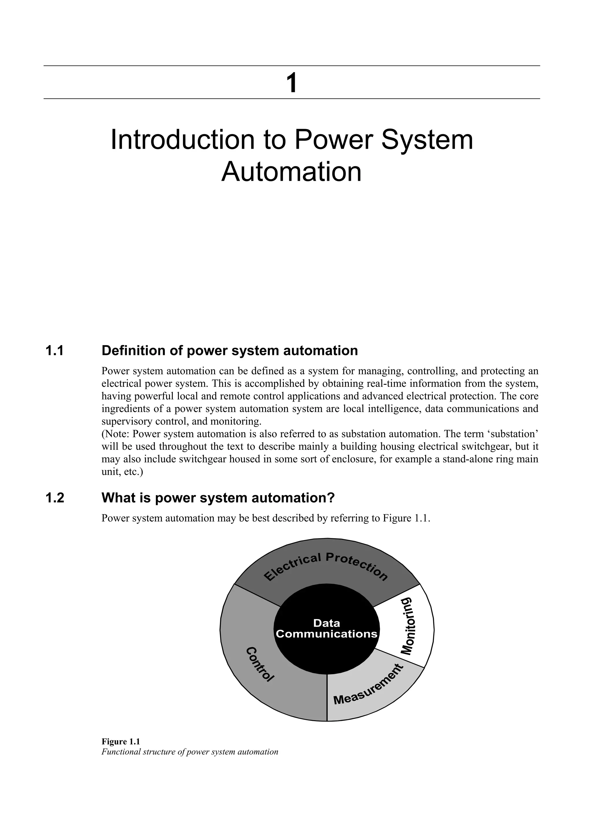
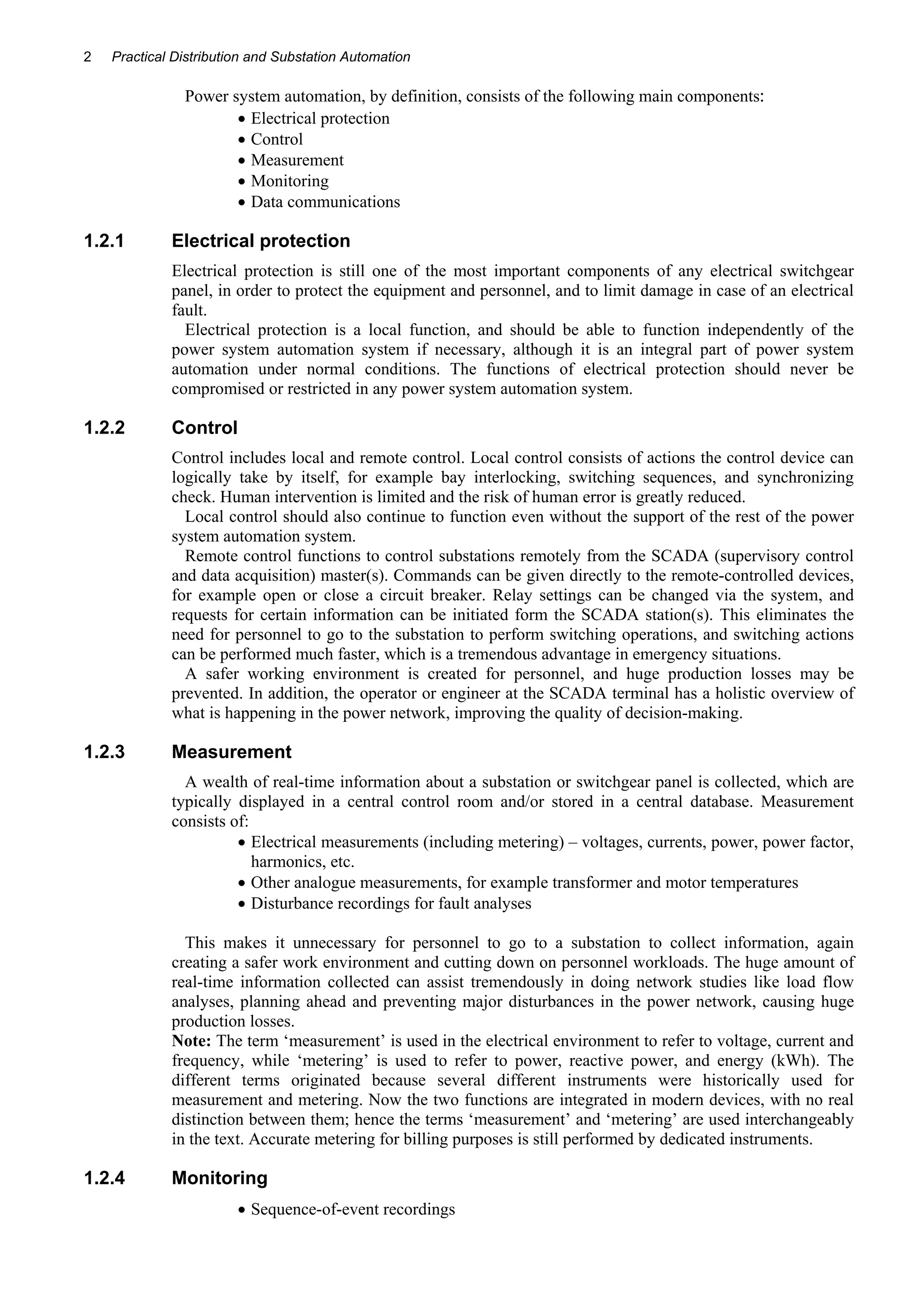
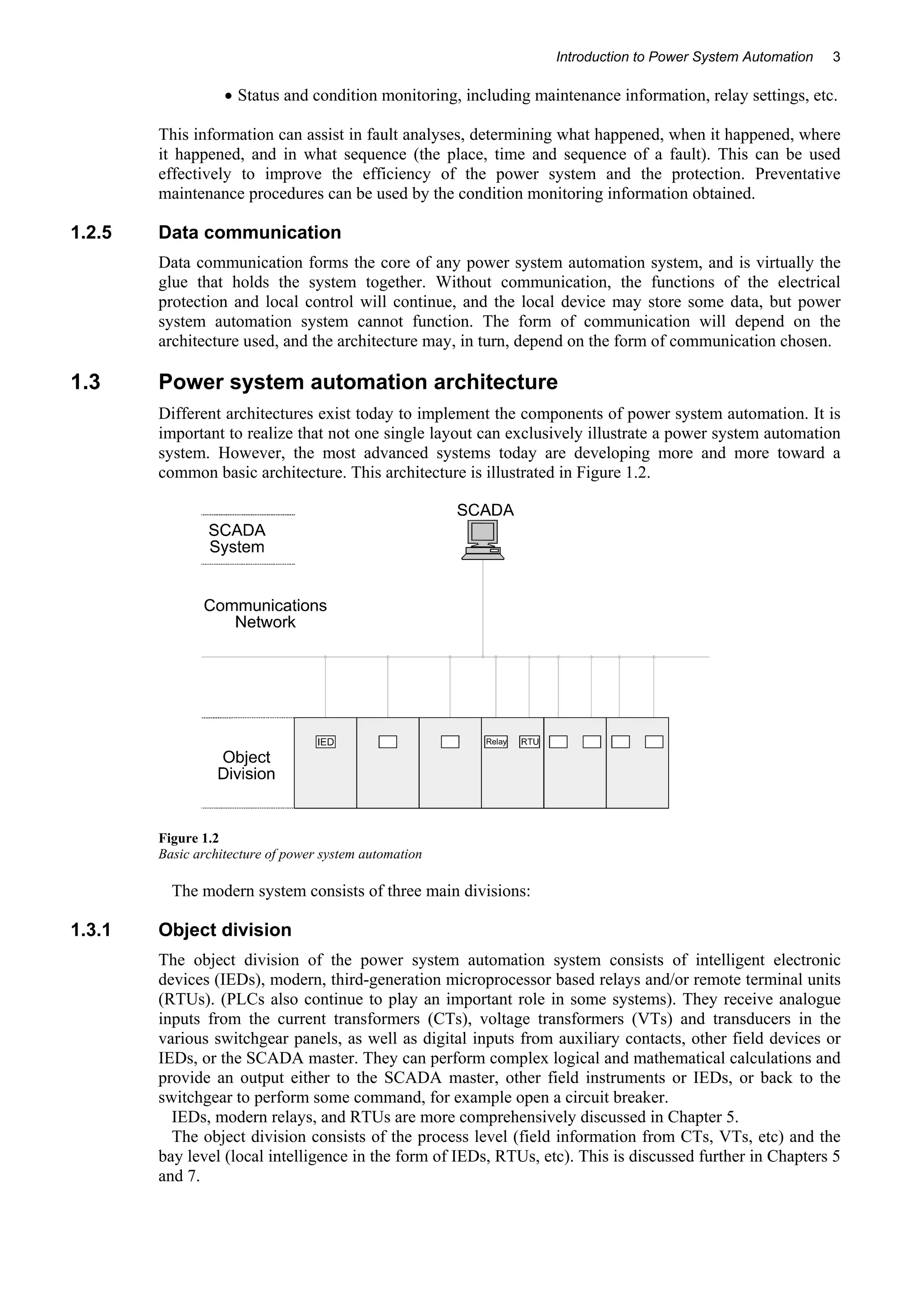
PRACTICAL 
DISTRIBUTION & 
SUBSTATION 
AUTOMATION 
(INCL. COMMUNICATIONS) 
FOR ELECTRICAL POWER SYSTEMS
1 
Introduction to Power System 
Automation 
1.1 Definition of power system automation 
Power system automation can be defined as a system for managing, controlling, and protecting an 
electrical power system. This is accomplished by obtaining real-time information from the system, 
having powerful local and remote control applications and advanced electrical protection. The core 
ingredients of a power system automation system are local intelligence, data communications and 
supervisory control, and monitoring. 
(Note: Power system automation is also referred to as substation automation. The term ‘substation’ 
will be used throughout the text to describe mainly a building housing electrical switchgear, but it 
may also include switchgear housed in some sort of enclosure, for example a stand-alone ring main 
unit, etc.) 
1.2 What is power system automation? 
Power system automation may be best described by referring to Figure 1.1. 
Figure 1.1 
Functional structure of power system automation
2 Practical Distribution and Substation Automation 
Power system automation, by definition, consists of the following main components: 
• Electrical protection 
• Control 
• Measurement 
• Monitoring 
• Data communications 
1.2.1 Electrical protection 
Electrical protection is still one of the most important components of any electrical switchgear 
panel, in order to protect the equipment and personnel, and to limit damage in case of an electrical 
fault. 
Electrical protection is a local function, and should be able to function independently of the 
power system automation system if necessary, although it is an integral part of power system 
automation under normal conditions. The functions of electrical protection should never be 
compromised or restricted in any power system automation system. 
1.2.2 Control 
Control includes local and remote control. Local control consists of actions the control device can 
logically take by itself, for example bay interlocking, switching sequences, and synchronizing 
check. Human intervention is limited and the risk of human error is greatly reduced. 
Local control should also continue to function even without the support of the rest of the power 
system automation system. 
Remote control functions to control substations remotely from the SCADA (supervisory control 
and data acquisition) master(s). Commands can be given directly to the remote-controlled devices, 
for example open or close a circuit breaker. Relay settings can be changed via the system, and 
requests for certain information can be initiated form the SCADA station(s). This eliminates the 
need for personnel to go to the substation to perform switching operations, and switching actions 
can be performed much faster, which is a tremendous advantage in emergency situations. 
A safer working environment is created for personnel, and huge production losses may be 
prevented. In addition, the operator or engineer at the SCADA terminal has a holistic overview of 
what is happening in the power network, improving the quality of decision-making. 
1.2.3 Measurement 
A wealth of real-time information about a substation or switchgear panel is collected, which are 
typically displayed in a central control room and/or stored in a central database. Measurement 
consists of: 
• Electrical measurements (including metering) – voltages, currents, power, power factor, 
harmonics, etc. 
• Other analogue measurements, for example transformer and motor temperatures 
• Disturbance recordings for fault analyses 
This makes it unnecessary for personnel to go to a substation to collect information, again 
creating a safer work environment and cutting down on personnel workloads. The huge amount of 
real-time information collected can assist tremendously in doing network studies like load flow 
analyses, planning ahead and preventing major disturbances in the power network, causing huge 
production losses. 
Note: The term ‘measurement’ is used in the electrical environment to refer to voltage, current and 
frequency, while ‘metering’ is used to refer to power, reactive power, and energy (kWh). The 
different terms originated because several different instruments were historically used for 
measurement and metering. Now the two functions are integrated in modern devices, with no real 
distinction between them; hence the terms ‘measurement’ and ‘metering’ are used interchangeably 
in the text. Accurate metering for billing purposes is still performed by dedicated instruments. 
1.2.4 Monitoring 
• Sequence-of-event recordings
Introduction to Power System Automation 3 
• Status and condition monitoring, including maintenance information, relay settings, etc. 
This information can assist in fault analyses, determining what happened, when it happened, where 
it happened, and in what sequence (the place, time and sequence of a fault). This can be used 
effectively to improve the efficiency of the power system and the protection. Preventative 
maintenance procedures can be used by the condition monitoring information obtained. 
1.2.5 Data communication 
Data communication forms the core of any power system automation system, and is virtually the 
glue that holds the system together. Without communication, the functions of the electrical 
protection and local control will continue, and the local device may store some data, but power 
system automation system cannot function. The form of communication will depend on the 
architecture used, and the architecture may, in turn, depend on the form of communication chosen. 
1.3 Power system automation architecture 
Different architectures exist today to implement the components of power system automation. It is 
important to realize that not one single layout can exclusively illustrate a power system automation 
system. However, the most advanced systems today are developing more and more toward a 
common basic architecture. This architecture is illustrated in Figure 1.2. 
Figure 1.2 
Basic architecture of power system automation 
The modern system consists of three main divisions: 
1.3.1 Object division 
The object division of the power system automation system consists of intelligent electronic 
devices (IEDs), modern, third-generation microprocessor based relays and/or remote terminal units 
(RTUs). (PLCs also continue to play an important role in some systems). They receive analogue 
inputs from the current transformers (CTs), voltage transformers (VTs) and transducers in the 
various switchgear panels, as well as digital inputs from auxiliary contacts, other field devices or 
IEDs, or the SCADA master. They can perform complex logical and mathematical calculations and 
provide an output either to the SCADA master, other field instruments or IEDs, or back to the 
switchgear to perform some command, for example open a circuit breaker. 
IEDs, modern relays, and RTUs are more comprehensively discussed in Chapter 5. 
The object division consists of the process level (field information from CTs, VTs, etc) and the 
bay level (local intelligence in the form of IEDs, RTUs, etc). This is discussed further in Chapters 5 
and 7.
4 Practical Distribution and Substation Automation 
1.3.2 The communications network 
The communications network (comms network for short) is virtually the nervous system of power 
system automation. The comms network ensures that raw data, processed information, and 
commands are relayed quickly, effectively and error-free among the various field instruments, 
IEDs and the SCADA system. The physical medium will predominantly be fiber-optic cables in 
modern networks, although some copper wiring will still exist between the various devices inside a 
substation. 
The comms network need to be an ‘intelligent’ subsystem in its own right to perform the 
functions required of it, and is not merely a network of fiber-optic and copper wiring. 
Communications are discussed in more detail in Chapters 8, 10 and 11 
The communication network serves as the interface between the bay level and the SCADA 
station level, which might be a SCADA master station in the substation itself, or remotely in a 
central control room. 
1.3.3 SCADA master 
The SCADA (supervisory control and data acquisition) master station(s) forms the virtual brain of 
the power system automation system. The SCADA master receives data and information from the 
field, decides what to do with it, stores it (directly or after some form of processing), and issues 
requests and/or commands to the remote devices. Therefore, the SCADA master is effectively in 
control of the complete power system automation system. 
Now, a SCADA master consists simply of an advanced, reliable PC or workstation (with its 
peripheral and support hardware) and a SCADA software. (In contrast with a few years ago when 
SCADA systems used to run on big main-frame computers or some form of complex proprietary 
hardware). 
A SCADA master station may be installed in each substation of a power transmission network 
(station level), with all the substation SCADA stations forming part of a LAN or WAN (network 
level); or one SCADA master station may be directly in control of several substations, eliminating 
the station level. 
SCADA systems are comprehensively covered in Chapter 9. 
1.4 Summary 
From the preliminary discussion in this chapter one can conclude that the principles of power 
system automation is not similar to process automation applied to a substation, but is in fact a 
totally different concept. 
Chapter 2 reviews the historical development of power system automation, as it developed to its 
present day technological status due to, and sometimes parallel to, technological developments in 
various other related industries. 
An overview of electrical power networks and the fundamental principles of electrical protection 
is necessary to fully appreciate the multitude of benefits a power system automation system can 
bring to the network, and to put it into perspective regarding electrical power transmission and 
distribution. These are the subjects of Chapters 3 and 4, respectively. 
Chapter 5 gives an introduction to substation automation functions and describes the different 
devices used to gain remote access to substations through a SCADA system, namely RTUs, PLCs, 
and IEDs. 
The main different architectures available today to implement a power system automation system 
are reviewed in Chapter 6. 
Chapter 7 covers the modern trends in current and voltage measurement. 
Chapter 8 looks at the communication requirements for various substation automation functions. 
Chapter 9 briefly presents the requirements of the SCADA master station for power system 
automation. 
Data communication is central to any power system automation system. The principles of data 
communications are discussed in Chapter 10, and some of the most important and widely used 
communication protocols are reviewed in Chapter 11. 
Chapter 12 is devoted to the IEC 61850 protocol specifically developed for data communications 
in substations and power automation networks.
Introduction to Power System Automation 5 
Chapter 13 discusses some of the security issues associated with the substation automation 
environment. 
Examples of some leading manufacturers’ power system automation products are discussed in 
Chapter 14. 
Chapter 15 discusses some important implementation issues for substation automation. 
Appendix A is a White Paper discussing Practical Substation Design Considerations and 
Appendix B discusses Standard Alarm arrangements for substations.
6 Practical Distribution and Substation Automation

Practical Distribution & Substation Automation (Incl. Communications) for Electrical Power Systems

  • 1.
    PRACTICAL DISTRIBUTION & SUBSTATION AUTOMATION (INCL. COMMUNICATIONS) FOR ELECTRICAL POWER SYSTEMS
  • 2.
    1 Introduction toPower System Automation 1.1 Definition of power system automation Power system automation can be defined as a system for managing, controlling, and protecting an electrical power system. This is accomplished by obtaining real-time information from the system, having powerful local and remote control applications and advanced electrical protection. The core ingredients of a power system automation system are local intelligence, data communications and supervisory control, and monitoring. (Note: Power system automation is also referred to as substation automation. The term ‘substation’ will be used throughout the text to describe mainly a building housing electrical switchgear, but it may also include switchgear housed in some sort of enclosure, for example a stand-alone ring main unit, etc.) 1.2 What is power system automation? Power system automation may be best described by referring to Figure 1.1. Figure 1.1 Functional structure of power system automation
  • 3.
    2 Practical Distributionand Substation Automation Power system automation, by definition, consists of the following main components: • Electrical protection • Control • Measurement • Monitoring • Data communications 1.2.1 Electrical protection Electrical protection is still one of the most important components of any electrical switchgear panel, in order to protect the equipment and personnel, and to limit damage in case of an electrical fault. Electrical protection is a local function, and should be able to function independently of the power system automation system if necessary, although it is an integral part of power system automation under normal conditions. The functions of electrical protection should never be compromised or restricted in any power system automation system. 1.2.2 Control Control includes local and remote control. Local control consists of actions the control device can logically take by itself, for example bay interlocking, switching sequences, and synchronizing check. Human intervention is limited and the risk of human error is greatly reduced. Local control should also continue to function even without the support of the rest of the power system automation system. Remote control functions to control substations remotely from the SCADA (supervisory control and data acquisition) master(s). Commands can be given directly to the remote-controlled devices, for example open or close a circuit breaker. Relay settings can be changed via the system, and requests for certain information can be initiated form the SCADA station(s). This eliminates the need for personnel to go to the substation to perform switching operations, and switching actions can be performed much faster, which is a tremendous advantage in emergency situations. A safer working environment is created for personnel, and huge production losses may be prevented. In addition, the operator or engineer at the SCADA terminal has a holistic overview of what is happening in the power network, improving the quality of decision-making. 1.2.3 Measurement A wealth of real-time information about a substation or switchgear panel is collected, which are typically displayed in a central control room and/or stored in a central database. Measurement consists of: • Electrical measurements (including metering) – voltages, currents, power, power factor, harmonics, etc. • Other analogue measurements, for example transformer and motor temperatures • Disturbance recordings for fault analyses This makes it unnecessary for personnel to go to a substation to collect information, again creating a safer work environment and cutting down on personnel workloads. The huge amount of real-time information collected can assist tremendously in doing network studies like load flow analyses, planning ahead and preventing major disturbances in the power network, causing huge production losses. Note: The term ‘measurement’ is used in the electrical environment to refer to voltage, current and frequency, while ‘metering’ is used to refer to power, reactive power, and energy (kWh). The different terms originated because several different instruments were historically used for measurement and metering. Now the two functions are integrated in modern devices, with no real distinction between them; hence the terms ‘measurement’ and ‘metering’ are used interchangeably in the text. Accurate metering for billing purposes is still performed by dedicated instruments. 1.2.4 Monitoring • Sequence-of-event recordings
  • 4.
    Introduction to PowerSystem Automation 3 • Status and condition monitoring, including maintenance information, relay settings, etc. This information can assist in fault analyses, determining what happened, when it happened, where it happened, and in what sequence (the place, time and sequence of a fault). This can be used effectively to improve the efficiency of the power system and the protection. Preventative maintenance procedures can be used by the condition monitoring information obtained. 1.2.5 Data communication Data communication forms the core of any power system automation system, and is virtually the glue that holds the system together. Without communication, the functions of the electrical protection and local control will continue, and the local device may store some data, but power system automation system cannot function. The form of communication will depend on the architecture used, and the architecture may, in turn, depend on the form of communication chosen. 1.3 Power system automation architecture Different architectures exist today to implement the components of power system automation. It is important to realize that not one single layout can exclusively illustrate a power system automation system. However, the most advanced systems today are developing more and more toward a common basic architecture. This architecture is illustrated in Figure 1.2. Figure 1.2 Basic architecture of power system automation The modern system consists of three main divisions: 1.3.1 Object division The object division of the power system automation system consists of intelligent electronic devices (IEDs), modern, third-generation microprocessor based relays and/or remote terminal units (RTUs). (PLCs also continue to play an important role in some systems). They receive analogue inputs from the current transformers (CTs), voltage transformers (VTs) and transducers in the various switchgear panels, as well as digital inputs from auxiliary contacts, other field devices or IEDs, or the SCADA master. They can perform complex logical and mathematical calculations and provide an output either to the SCADA master, other field instruments or IEDs, or back to the switchgear to perform some command, for example open a circuit breaker. IEDs, modern relays, and RTUs are more comprehensively discussed in Chapter 5. The object division consists of the process level (field information from CTs, VTs, etc) and the bay level (local intelligence in the form of IEDs, RTUs, etc). This is discussed further in Chapters 5 and 7.
  • 5.
    4 Practical Distributionand Substation Automation 1.3.2 The communications network The communications network (comms network for short) is virtually the nervous system of power system automation. The comms network ensures that raw data, processed information, and commands are relayed quickly, effectively and error-free among the various field instruments, IEDs and the SCADA system. The physical medium will predominantly be fiber-optic cables in modern networks, although some copper wiring will still exist between the various devices inside a substation. The comms network need to be an ‘intelligent’ subsystem in its own right to perform the functions required of it, and is not merely a network of fiber-optic and copper wiring. Communications are discussed in more detail in Chapters 8, 10 and 11 The communication network serves as the interface between the bay level and the SCADA station level, which might be a SCADA master station in the substation itself, or remotely in a central control room. 1.3.3 SCADA master The SCADA (supervisory control and data acquisition) master station(s) forms the virtual brain of the power system automation system. The SCADA master receives data and information from the field, decides what to do with it, stores it (directly or after some form of processing), and issues requests and/or commands to the remote devices. Therefore, the SCADA master is effectively in control of the complete power system automation system. Now, a SCADA master consists simply of an advanced, reliable PC or workstation (with its peripheral and support hardware) and a SCADA software. (In contrast with a few years ago when SCADA systems used to run on big main-frame computers or some form of complex proprietary hardware). A SCADA master station may be installed in each substation of a power transmission network (station level), with all the substation SCADA stations forming part of a LAN or WAN (network level); or one SCADA master station may be directly in control of several substations, eliminating the station level. SCADA systems are comprehensively covered in Chapter 9. 1.4 Summary From the preliminary discussion in this chapter one can conclude that the principles of power system automation is not similar to process automation applied to a substation, but is in fact a totally different concept. Chapter 2 reviews the historical development of power system automation, as it developed to its present day technological status due to, and sometimes parallel to, technological developments in various other related industries. An overview of electrical power networks and the fundamental principles of electrical protection is necessary to fully appreciate the multitude of benefits a power system automation system can bring to the network, and to put it into perspective regarding electrical power transmission and distribution. These are the subjects of Chapters 3 and 4, respectively. Chapter 5 gives an introduction to substation automation functions and describes the different devices used to gain remote access to substations through a SCADA system, namely RTUs, PLCs, and IEDs. The main different architectures available today to implement a power system automation system are reviewed in Chapter 6. Chapter 7 covers the modern trends in current and voltage measurement. Chapter 8 looks at the communication requirements for various substation automation functions. Chapter 9 briefly presents the requirements of the SCADA master station for power system automation. Data communication is central to any power system automation system. The principles of data communications are discussed in Chapter 10, and some of the most important and widely used communication protocols are reviewed in Chapter 11. Chapter 12 is devoted to the IEC 61850 protocol specifically developed for data communications in substations and power automation networks.
  • 6.
    Introduction to PowerSystem Automation 5 Chapter 13 discusses some of the security issues associated with the substation automation environment. Examples of some leading manufacturers’ power system automation products are discussed in Chapter 14. Chapter 15 discusses some important implementation issues for substation automation. Appendix A is a White Paper discussing Practical Substation Design Considerations and Appendix B discusses Standard Alarm arrangements for substations.
  • 7.
    6 Practical Distributionand Substation Automation