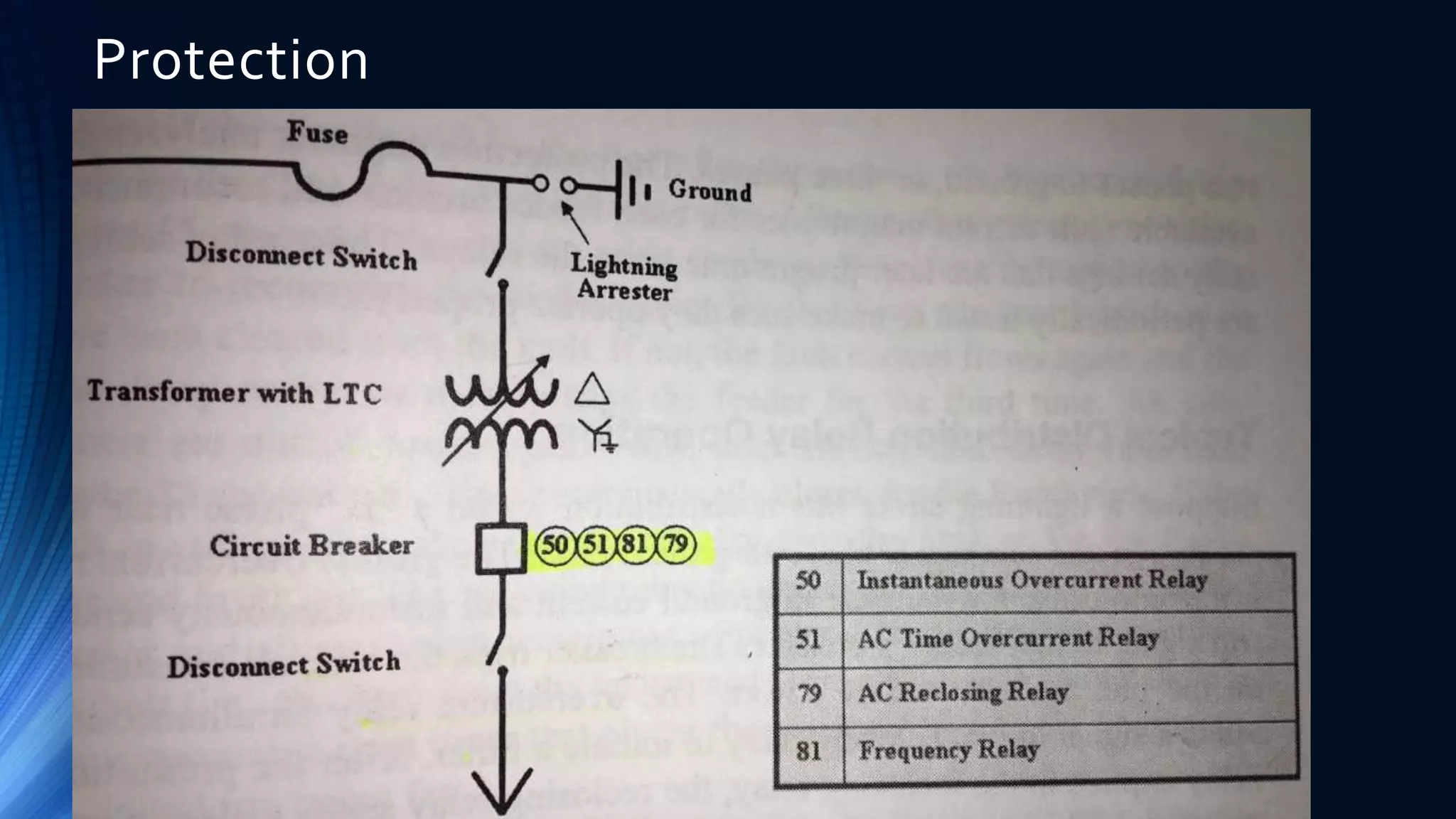
Chapter 7 System Protection
Two Types of Protection
• System Protection deals with the electric grid using
• Protective Relays, fault currents, grounding, circuit breakers, fuses, etc.
• Personal Protection deals with safety
• Rubber gloves and blankets, grounding jumpers, tagging, etc
• This chapter is about SYSTEM PROTECTION.
Objective of System Protection
• Remove faulted equipment from the grid before it damages other
equipment.
• Protection of equipment is key; it is not intended to protect people
• Protects equipment from power faults and/or lightning
• Effective equipment grounding enhances system protection
• Relays operate faster, lightning is directed to earth
Protective Relaying
• Relay devices monitor the power system’s voltages and currents through
CTs and PTs.
• Programmed to initiateTrip or Close signals to CBs when settings are exceeded
• Also send alarms to System Operators
• All Battery Powered (DC) so they are functional if main AC power is out
• The Stabilizing force against unwanted Destabilizing forces (faults)
• Protective Relays are
• Electromechanical
• Solid State
Electromechanical
• Composed of coils of wire, magnets, spinning disks and
electrical contacts. Very Mechanical in nature.
• Advantages
• Self Powered, simple-single function design (ie Overcurrent Relay,
Underfrequency Relay)
• Absolutely Secure – Can’t be “hacked”
• Disadvantages
• One relay per phase, difficult to set up, adjust and requires more
frequent maintenance and testing
Solid State (electronic/microprocessor)
• Electronic with No moving parts. Modern
• Advantages
• Multi-function (TOC, UnderFreq, UnderVolt, differential, etc.)
• Small space requirements
• Some self-testing
• Remote access
• Fault location and advanced information storage
• Disadvantages
• External Power Required
• Software can be complex
• Many “eggs” or functions in one “basket” or device.
Inverse Time – Current Concept
• The time to trip a circuit breaker shortens as the fault current increases
• High Faults close to a substation, CB can open in less than 2 cycles
• Minimum Pickup (or trip) Setting – Never trips below this setting
• InstantaneousTrip Setting –Trip as fast as possible; no time delay
Inverse Time
Current Curves
Coordination:
Transformer
Protection
Fuse Only
Coordination:
Transformer
Protection
CB & Fuse
Distribution Protection Schemes
• Feeders are normally fed Radially out of stations
• Power flows in one direction…downline
• Typical Protection:
• Underfrequency Relays
• Overcurrent Protection with Reclosing Relays
• A,B,C and G
• Instantaneous (50) andTime OverCurrent (51)
• Measurements taken from CTs mounted directly on CB bushing
• Senses fault types of L-G, L-L, L-L-L
Protection
Distribution Protection Schemes
• Temporary Faults (Lightning) – Open Instantaneous then
Close before downline fuses blow.
• Permanent Faults (Tree, Car) – O/C, O/C, O/C, Lockout OR
downline fuse blows before lockout.
Relay Coordination
• Goal: Remove faulted element with the least customers out
• Most downstream clearing device from the fault clears the fault first
• Upstream devices act as backup clearing devices
Transmission Protection
• Much different than distribution protection because lines
are normally loop fed.
• Multiple Generation Sources, Buses, Lines, Substations
and Circuit Breakers
• Power Flow can occur in either direction on theT-Lines
• Zone or Distance Relaying
• Zones overlap to provide Redundancy
• CTs & PTs used extensively to “feed” quantities to relays
Transmission Protection
• Directional Relaying detects which bus the fault is
located
• Over and UnderVoltage Relays
• Turn on andTurn off Station Capacitor Banks
• Trip breakers for abnormal conditions
• Differential Relay Protection for buses, transformers,
generators
• Power in must equal Power out
• If not, there is a problem, so we trip
Generator Protection
• Differential Relays forWinding Short Ckt Protection
• Field Ground Protection
• Motoring
• Lack of mechanical energy from prime mover
• Power flows INTO the Generator
• Underfrequency Relay for Loss of Excitation
• Could lose synchronism
• Frequency Relays
• Volts per Hz relays
Generator Synchronization
• Synchronization Relay purpose is to connect 2 lines
together OR place a spinning generator online.
• Permissive Relays “look” for 4 conditions:
• 1 Frequency (60 Hz both sides of CB)
• 2Voltage (Magnitudes match both sides of CB)
• 3 Phase Angle (Sine waves match both sides of CB)
• 4 Rotation (ABC)
Read Chapter 7!

14362648-Chapter 7 System Protection.ppt

  • 1.
    Chapter 7 SystemProtection
  • 2.
    Two Types ofProtection • System Protection deals with the electric grid using • Protective Relays, fault currents, grounding, circuit breakers, fuses, etc. • Personal Protection deals with safety • Rubber gloves and blankets, grounding jumpers, tagging, etc • This chapter is about SYSTEM PROTECTION.
  • 3.
    Objective of SystemProtection • Remove faulted equipment from the grid before it damages other equipment. • Protection of equipment is key; it is not intended to protect people • Protects equipment from power faults and/or lightning • Effective equipment grounding enhances system protection • Relays operate faster, lightning is directed to earth
  • 4.
    Protective Relaying • Relaydevices monitor the power system’s voltages and currents through CTs and PTs. • Programmed to initiateTrip or Close signals to CBs when settings are exceeded • Also send alarms to System Operators • All Battery Powered (DC) so they are functional if main AC power is out • The Stabilizing force against unwanted Destabilizing forces (faults) • Protective Relays are • Electromechanical • Solid State
  • 5.
    Electromechanical • Composed ofcoils of wire, magnets, spinning disks and electrical contacts. Very Mechanical in nature. • Advantages • Self Powered, simple-single function design (ie Overcurrent Relay, Underfrequency Relay) • Absolutely Secure – Can’t be “hacked” • Disadvantages • One relay per phase, difficult to set up, adjust and requires more frequent maintenance and testing
  • 6.
    Solid State (electronic/microprocessor) •Electronic with No moving parts. Modern • Advantages • Multi-function (TOC, UnderFreq, UnderVolt, differential, etc.) • Small space requirements • Some self-testing • Remote access • Fault location and advanced information storage • Disadvantages • External Power Required • Software can be complex • Many “eggs” or functions in one “basket” or device.
  • 7.
    Inverse Time –Current Concept • The time to trip a circuit breaker shortens as the fault current increases • High Faults close to a substation, CB can open in less than 2 cycles • Minimum Pickup (or trip) Setting – Never trips below this setting • InstantaneousTrip Setting –Trip as fast as possible; no time delay
  • 8.
  • 9.
  • 10.
  • 11.
    Distribution Protection Schemes •Feeders are normally fed Radially out of stations • Power flows in one direction…downline • Typical Protection: • Underfrequency Relays • Overcurrent Protection with Reclosing Relays • A,B,C and G • Instantaneous (50) andTime OverCurrent (51) • Measurements taken from CTs mounted directly on CB bushing • Senses fault types of L-G, L-L, L-L-L
  • 12.
  • 13.
    Distribution Protection Schemes •Temporary Faults (Lightning) – Open Instantaneous then Close before downline fuses blow. • Permanent Faults (Tree, Car) – O/C, O/C, O/C, Lockout OR downline fuse blows before lockout.
  • 14.
    Relay Coordination • Goal:Remove faulted element with the least customers out • Most downstream clearing device from the fault clears the fault first • Upstream devices act as backup clearing devices
  • 15.
    Transmission Protection • Muchdifferent than distribution protection because lines are normally loop fed. • Multiple Generation Sources, Buses, Lines, Substations and Circuit Breakers • Power Flow can occur in either direction on theT-Lines • Zone or Distance Relaying • Zones overlap to provide Redundancy • CTs & PTs used extensively to “feed” quantities to relays
  • 16.
    Transmission Protection • DirectionalRelaying detects which bus the fault is located • Over and UnderVoltage Relays • Turn on andTurn off Station Capacitor Banks • Trip breakers for abnormal conditions • Differential Relay Protection for buses, transformers, generators • Power in must equal Power out • If not, there is a problem, so we trip
  • 17.
    Generator Protection • DifferentialRelays forWinding Short Ckt Protection • Field Ground Protection • Motoring • Lack of mechanical energy from prime mover • Power flows INTO the Generator • Underfrequency Relay for Loss of Excitation • Could lose synchronism • Frequency Relays • Volts per Hz relays
  • 18.
    Generator Synchronization • SynchronizationRelay purpose is to connect 2 lines together OR place a spinning generator online. • Permissive Relays “look” for 4 conditions: • 1 Frequency (60 Hz both sides of CB) • 2Voltage (Magnitudes match both sides of CB) • 3 Phase Angle (Sine waves match both sides of CB) • 4 Rotation (ABC)
  • 19.