Downloaded 11 times
![33 International Journal of Research in Science & Technology
Volume: 2 | Issue: 2 | February 2015 | ISSN: 2349-0845IJRST
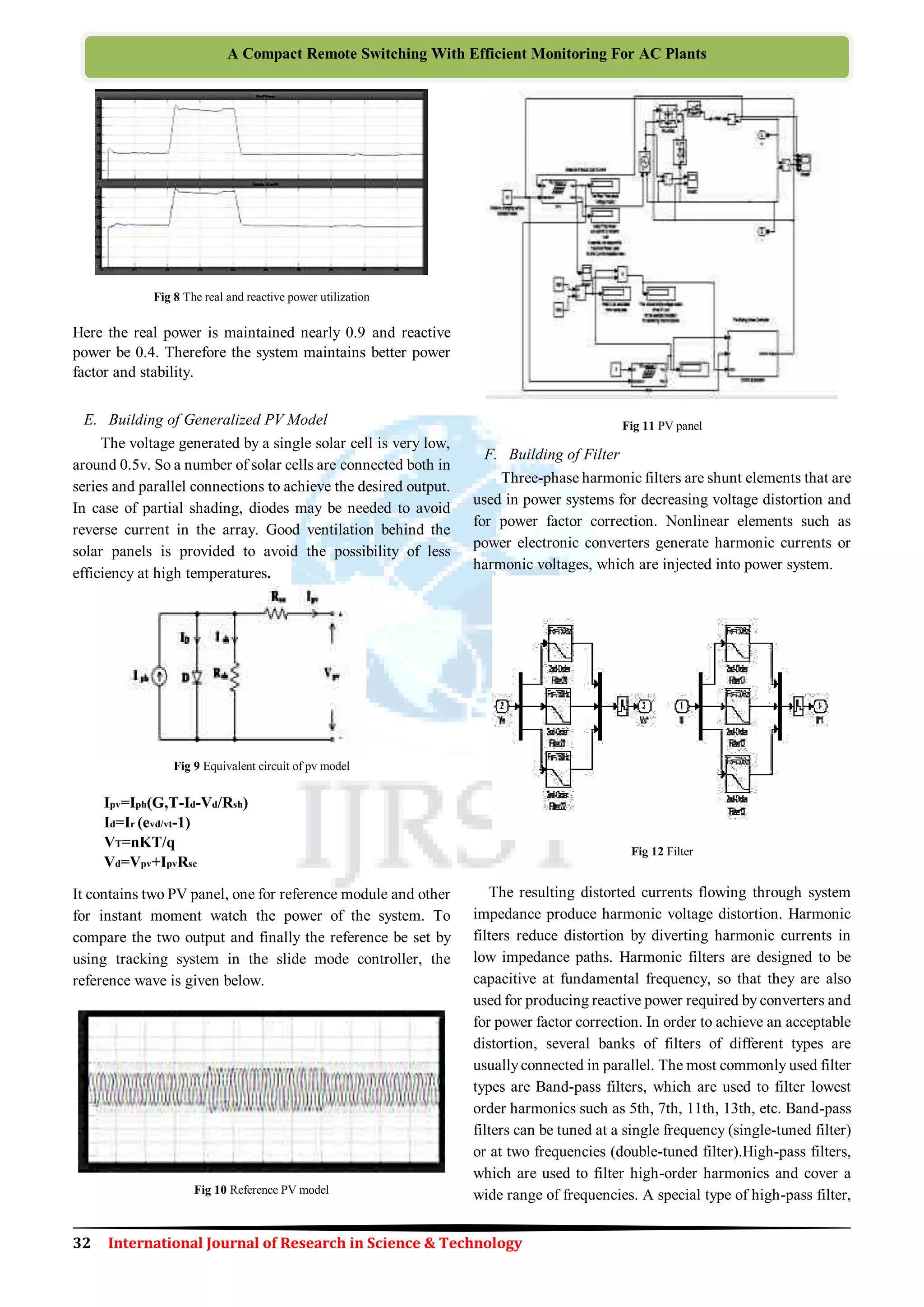
The C-type high-pass filter is used to provide reactive power
and avoid parallel resonances. It also allows filtering low
order harmonics (such as 3rd), while keeping zero losses at
fundamental frequency.
G. Subsystem
Fig 13 Subsystem
The subsystem contains the set point value as 1600. It
contains the input of the inverter (Vabc, Iabc, Vdc). It used to
rectifythe error byusing PI controller and finalized output be
produced and it is given to the gate terminal of the inverter
sections.
IV. CONCLUSION
Thus the simulation results are verified for the output
voltage is maintained constant for both grid side and load
side with the help of power electronics switches. The
effectiveness of the scheme is tested through simulations on a
realistic distribution network model. Proposed coordinated
reactive power dispatch, are reduced without detrimental
impact on the feeder voltage. By using the slide mode
controller, the constant voltage is maintained. By reducing
the voltage control mechanisms like on load tap changers
and autonomous regulators and capacitors etc. and also avoid
runaway condition and Life time of the system be improved.
REFERENCES
[1] Global market outlook for photovoltaic until 2016,” May 2012 [Online].
Available: http://www.epia.org/
[2] C. L. Masters, “Voltage rise: the big issue when connecting embedded
generation to long 11kv overhead lines,” Power Eng. J., vol. 16, no. 1, pp.
5–12, 2002.T.Stetz, Marten and Braun, “Improved low voltage
grid-integration of photovoltaic system in Germany” IEEE Trans Sustain
Energy, vol. 4, no. 2, pp. 534–542, Apr. 2013.
[3] A.G.Madureira and J. A. P. Lopes, “Voltage and reactive power control in
MV networks integrating micro grids,” Proc. ICREPQ, vol. 7, pp. 1–5,
2007.
[4] T. Basso, J. Ham brick, and D. DeBlasio, “Update and review of IEEE
p2030 smart grid IEEE 1547 inter connection standards,” Innovative
Smart Grid Technologies, pp. 1–7, 2012.
[5] “BDEW technical guideline for generating plants connected to the
medium-voltage network,” May 2012. [Online]. Available:
http://www.bdew.de
[6] F. Katiraei and J. R. Aguero, “Solar PV integration challenges,” IEEE
Power Energy Mag., vol. 9, no. 3, pp. 62–71, 2011.
[7] L. M. Cipcigan and P. C. Taylor, “Investigation of the reverse power flow
requirements of high penetrations of small-scale embedded generation,”
IET Renewable Power Gen., vol.1, no.3, pp.160–166, 2007.
[8] U.S. Dept. of Energy sun shot Initiative 2008 [Online]. Available:
https://solarhighpen.energy.gov/
[9] R. A. Walling, R. Saint, R. C. Dugan, J. Burke, and L. A. Kojovic,
“Summary of distributed resources impact on power delivery system,”
IEEE Trans. Power Del., vol. 23, no. 3, pp. 1636–1644, Jul. 2008
[10] R. H. Liang and C. K. Cheng, “Dispatch of main transformer ULTC and
capacitors in a distribution system,” IEEE Trans. Power Del., vol. 16, no.
4, pp. 625–630, Oct. 2001.
[11] R. A. Walling and K. Clark, “Grid support functions implemented in
utility-scale PV system,” in Proc. IEEE PES Trans, Distribution. Conf.
Expo., 2010, pp. 1–5.
[12] W. H. Ker sting, Distribution System Modeling and Analysis. Boca
Raton, FL, USA: CRC, 2002.
[13] “McGraw-Edison VR-32 regulators and CL-5 series control,” Cooper
Ind. [Online]. Available: http://www.cooperindustries.com.
[14] “MJ-4A(TM) AND MJ-4B(TM) voltage regulator control panel,”
Siemens [Online]. Available: http://www.energy.siemens.com/.
[15] P. A. N. Garcia, J. L. R. Pereira, S. C. Jr, V. M. daCosta, and N. Martins,
“Three-phase power flow calculations using the current injection
method,” , IEEE Trans. Power Syst., vol. 15, no. 2, pp. 508–514, May
2000.
[16] E. T. Jauch, “Possible effects of smart grid functions on LTC trans-
formers,” IEEE Trans. Ind. Appl., vol. 47, no. 2, pp. 1013–1021, Mar.
–Apr. 2011.
[17] R.A. Jabr, A.H. Coonick, and B.J.Cory,“A primal-dual interior point
method for optimal power flow dispatching,” IEEE Trans. Power Syst.,
vol. 17, no. 3, pp. 654–662, Aug. 2002.
[18] S. J. Wright, Primal-Dual Interior-Point Methods. Philadelphia, PA,
USA: Soc. for Ind. Appl. Math., 1997, vol. 54.
[19] W. J. Smolensk, “Equivalent circuit analysis of power system reactive
power and voltage control problems,” IEEE Trans. Power App. Syst, vol.
PAS-100, no. 2, pp. 837–842, 1981.
[20] M. B. Liu, C. A. Canizares, and W. Huang, “Reactive power and voltage
control in distribution system with limited switching operations,” IEEE
Trans. Power Syst., vol. 24, no. 2, pp. 889–899, May 2009.
[21] S. Paudyal, C. A. Canizares, and K. Bhattacharya, “Optimal operation of
distribution feeders in smart grids,” IEEE Trans. Ind. Electron.,vol. 58,
no. 10, pp. 4495–4503, Oct. 2011.
[22] T. E. McDermott, “Modeling PV for unbalanced, dynamic and quasistatic
distribution system analysis, ”in Proc. IEEE Power Energy Soc. Gen.
Meet., 2011, pp. 1–3.
[23] M. Fila, G. A. Taylor, M. R. Irving, J. His cock, P. Lang, and P. Aston,
“Systematic modeling and analysis of tap voltage control schemes,” in
Proc. IEEE 42nd Int. Universities Power Eng. Conf., 2007, pp.
349–356.A.Malekpour and A. Pahwa, “Reactive power and voltage
control in distribution system with photo voltaic generation,” in Proc.
IEEE North Amer. Power Sym., 2012, pp. 1–6.
S.RAHUMATH BEEVI received the B.E degree In
Electronics and communication engineering from PSN
College of engineering technology Tirunelveli in 2013.
And currently doing the Master degree in Power electronics
and Drives from PET engineering College valliyur,
Tirunelveli in 2015. And also interested in distribution &
transmission systems.
A.SUBANTH WILLIAMS received the B.E degree in
electrical and electronics engineering in Jeyamatha
engineering college, Aralvaimozhi and M.E degrees in
power electronics and drives. He is a Professor with the
Department of electrical Engineering in PET engineering
college, valliyur. His research interests include the area
under the Power Quality. And also he is the member of
MISTE.
L.YOUSUF SIDDIQUE received the B.E degree in electrical and electronics
engineering in National College of engineering, Maruthakulam, Tirunelveli
and M.E degrees in power system from ANNA University of Technology
Trichy. He is a Professor with the Department of electrical Engineering in PET
engineering college, valliyur.](https://image.slidesharecdn.com/ijrst020206-150223231039-conversion-gate01/75/Reactive-Power-Compensation-in-Distribution-Network-with-Slide-Mode-MPPT-Control-for-PV-System-5-2048.jpg)

This document discusses using a sliding mode controller with maximum power point tracking (MPPT) for voltage control in a grid-connected photovoltaic power system. It begins with an introduction to solar energy and MPPT. It then describes the proposed system, which uses a sliding mode controller to balance power flow from the PV panel to the grid and load. Simulation results show the system maintaining constant voltage on both the grid and load sides while effectively utilizing the PV power. The design aims to improve on traditional voltage control mechanisms and improve system lifetime.