Downloaded 15 times
![International
OPEN ACCESS Journal
Of Modern Engineering Research (IJMER)
| IJMER | ISSN: 2249–6645 | www.ijmer.com | Vol. 4 | Iss. 6| June. 2014 | 59|
Design of 8-Bit Comparator Using 45nm CMOS Technology
Ranjeet Kumar1
, Prof. S. R. Hirekhan2
1, 2
(Department of Electronics, Government College of Engineering Aurangabad, India)
I. Introduction
Binary comparator is widely used in digital system to compare between two numbers. Binary
comparators are found in a wide variety of circuits, such as microprocessors, communications systems,
encryption devices, and many others. A faster, more power efficient, or more compact comparator would be an
advantage in any of these circuits. A circuit that compares two binary numbers is called comparator. It also
decides whether both numbers are equal or not equal.
In this paper, we present two CMOS unsigned binary comparators. Our approaches is first to design 1-
bit comparator as one component and then generate its symbol to design 8-bit comparator.
Here we use Microwind3.1 to draw the layout of the CMOS circuit. Then we extract the spice file in
Microwind3.1 and run under PSPICE to get the simulation.
II. Previous Work
The current mode signal processing using CMOS technology has gained great interesting circuit
designing. With the shrinkage of feature size and increasing demand of high speed and low power application,
the current-mode circuit has been considered to be an alternative to voltage-mode circuit. Current comparator is
fundamental component of analog system because of better accuracy, low noise and low power consumption. It
can be used in A/D converters, oscillators, current to frequency converters, VLSI neural network, sensor circuit
and portable wireless communication etc. H. Traff [1] proposed the first high speed, low input impedance
current comparator using a simple inverter. Tarff’s approach has been modified by a number of designs, A. T.
K. Tang et al. [2] and L. Ravezzi et al.[3], where speed increases have been attained at the cost of an increase in
power consumption.
Several previous high-speed comparator designs have been proposed. In all[6]precharged function
block is attached to several feedback transistors which add extra discharge paths, thus reducing the comparator's
delay. However, the precharge period is not utilized for any computation, so the design is not as fast as our high-
speed design, as we will show in the sequel.
It is desirable that comparators must provide high speed and low power consumption. Here we need to
design such kind of a comparator which compares the value of two 8-bit numbers and output X becomes to 1
when the first number A is larger than the second number B, output Y becomes to 1 when the two numbers A
and B are equal and Z becomes 1 when both X and Y becomes zeros.
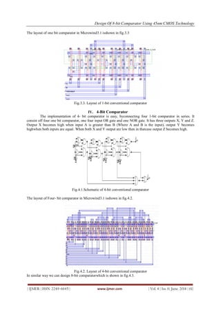
III. 1-Bit Comparator
First of all we need to design a 1 bit comparator. We can easily make such a component, 2 bits for
input A and B, and 2 bits for output X and Y. X is one when A is larger than B which means only when A is one
and B is zero will set X to one. And for the Y, only when A and B both become one and zero will it be set. Here
we can define.
X as X=A.B’
Y as Y = A.B +A’.B
Z as Z= (A+B)’
Second we draw the Karnaugh-map of 1-bit comparator and find the relationship between the input and the
output.
Abstract: In this paper design of 8- bit binary comparator using 45nm CMOS technology is discussed.
This design needs less area and less number of transistors, also discussed about power and execution time. The
circuit has three output X, Y and Z. X is active high, when A>B, Y is active high when A=B and Z is active high
when both X and Y are active low. Design 1- bit comparator with the help of precharge gate.The design of 1-bit
comparator has been extended to implement an 8-bit comparator by connecting in series with pass
transistor between them. The design has been implemented in Microwind3.1, is tested successfully and
has been validated using Pspice for different measurable parameter.
Keywords: Power, VLSI, 45nm CMOS technology, area, no of transistors, execution time.](https://image.slidesharecdn.com/ijmer-46015964-140714061413-phpapp01/85/Design-of-8-Bit-Comparator-Using-45nm-CMOS-Technology-1-320.jpg)


![Design Of 8-bit Comparator Using 45nm CMOS Technology
| IJMER | ISSN: 2249–6645 | www.ijmer.com | Vol. 4 | Iss. 6| June. 2014 | 64|
Bits No of
transistors
Execution Time Power
Dissipation(watts)
Are𝑎(𝜇𝑚)2
1 14 0.08 1.15E-12 7.41
4 59 0.30 4.94E-12 45.14
8 111 0.55 9.54E-12 104.34
Table: 6.2 Simulation Result for 8-bit comparator (proposed)
VII. Conclusion
This paper has described different designs for CMOS binary comparator and show different parameter
like area, power, execution time and number of transistor. This design needs less area and less number of
gates.CMOS circuit is used to construct the comparator by using the logic relation between different
input and output. A Karnaugh map is used to minimize the representation of function..
REFERENCES
[1]. H. Traff, “Noval approach to high speed CMOS current comparator,” Electron. Letter, vol. 28, no. 3, pp.
310- 312, Jan.1992.
[2]. A.T K. Tang and C. Toumazou, “High performance CMOS current comparator,” Electron. Letter, vol.
30, pp. 5-6, 1994.
[3]. L. Ravezzi, D. Stoppa and G. F. DallaBetta, “Simple High speed CMOS current comparator,” Electron.
Letter, vol.33, pp.1829-1830, 1997.
[4]. Current Comparator Design,” Electron.Letter, vol. 44, no.3, pp.171-172, Jan. 2008.
[5]. Ding Chengwei, NiuYuechao, “ 3-bit comparator design” Submicron Project, SoC 2005.
[6]. Eric R. Menendez, Dumezie K. Maduikez , Rajesh Garg, and Sunil P. Khatri, “CMOS Comparators for
High Speed and Low Power Applications” 1-4244-9707-X/06 ©2006 IEEE](https://image.slidesharecdn.com/ijmer-46015964-140714061413-phpapp01/85/Design-of-8-Bit-Comparator-Using-45nm-CMOS-Technology-6-320.jpg)

The document discusses the design of an 8-bit binary comparator using 45nm CMOS technology, emphasizing its advantages in terms of area, power consumption, and execution time. The design consists of a hierarchical structure starting from a 1-bit comparator and utilizes a precharged gate setup for efficient operation. Simulation results demonstrate the effectiveness of the proposed comparator in achieving high speed and low power consumption.