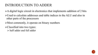
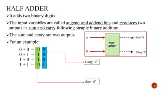
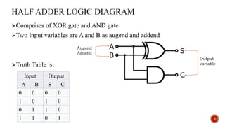
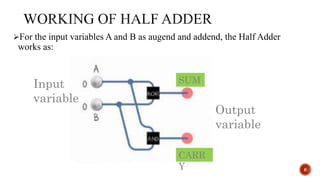
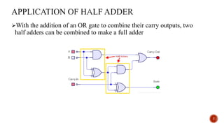
HALF ADDER
1
Presented by: Rabin BK
BSc.CSIT 2nd Semester
Introduction to Adder
What is Half Adder?
Half Adder Logic diagram
A glimpse at the working of Half adder
Application of Half Adder
References
2
A digital logic circuit in electronics that implements addition of 2 bits
Used to calculate addresses and table indices in the ALU and also in
other parts of the processors
Most commonly, it operate on binary numbers
Classified into two types:
 half adder and full adder
3
It adds two binary digits
The input variables are called augend and addend bits and produces two
outputs as sum and carry following simple binary addition
The sum and carry are two outputs
For an example:
0 + 0 = 0 0
0 + 1 = 1 0
1 + 0 = 1 0
1 + 1 = 0 1
4
Carry ‘C’
Sum ‘S’
Comprises of XOR gate and AND gate
Two input variables are A and B as augend and addend
Truth Table is:
5
Augend
Addend
Output
variable
Input Output
A B S C
0 0 0 0
1 0 1 0
0 1 1 0
1 1 0 1
For the input variables A and B as augend and addend, the Half Adder
works as:
6
Input
variable
Output
variable
SUM
CARR
Y
With the addition of an OR gate to combine their carry outputs, two
half adders can be combined to make a full adder
7
References
Web reference:
 https://www.elprocus.com/half-adder-and-full-adder/
 https://upload.wikimedia.org/wikipedia/commons/thumb/9/92/Halfadder.gif/220px-
Halfadder.gif
 http://theteacher.info/index.php/programming-development-1/2-logical-operations/all-
topics/3622-an-application-of-full-adders
 https://www.google.com.np/url?sa=t&rct=j&q=&esrc=s&source=web&cd=2&cad=rja&ua
ct=8&ved=0ahUKEwihmqX-2pbUAhXHtI8KHa-
DF4QFggjMAE&url=https%3A%2F%2Fen.wikipedia.org%2Fwiki%2FAdder_(electronic
s)&usg=AFQjCNFbLNz08tyf8ay0TMSApHtVnXoDGQ&sig2=5_allA9EWff09dqaizgkC
Q
 https://en.wikipedia.org/wiki/Adder_(electronics)
 http://www.lbpcentral.com/forums/showthread.php?51015-Practical-applications-for-
adder-subtraction-circuits-amp-7-bit-registers-e-t-c
8
Queries
9

Half Adder_Digital logic_

  • 1.
    HALF ADDER 1 Presented by:Rabin BK BSc.CSIT 2nd Semester
  • 2.
    Introduction to Adder Whatis Half Adder? Half Adder Logic diagram A glimpse at the working of Half adder Application of Half Adder References 2
  • 3.
    A digital logiccircuit in electronics that implements addition of 2 bits Used to calculate addresses and table indices in the ALU and also in other parts of the processors Most commonly, it operate on binary numbers Classified into two types:  half adder and full adder 3
  • 4.
    It adds twobinary digits The input variables are called augend and addend bits and produces two outputs as sum and carry following simple binary addition The sum and carry are two outputs For an example: 0 + 0 = 0 0 0 + 1 = 1 0 1 + 0 = 1 0 1 + 1 = 0 1 4 Carry ‘C’ Sum ‘S’
  • 5.
    Comprises of XORgate and AND gate Two input variables are A and B as augend and addend Truth Table is: 5 Augend Addend Output variable Input Output A B S C 0 0 0 0 1 0 1 0 0 1 1 0 1 1 0 1
  • 6.
    For the inputvariables A and B as augend and addend, the Half Adder works as: 6 Input variable Output variable SUM CARR Y
  • 7.
    With the additionof an OR gate to combine their carry outputs, two half adders can be combined to make a full adder 7
  • 8.
    References Web reference:  https://www.elprocus.com/half-adder-and-full-adder/ https://upload.wikimedia.org/wikipedia/commons/thumb/9/92/Halfadder.gif/220px- Halfadder.gif  http://theteacher.info/index.php/programming-development-1/2-logical-operations/all- topics/3622-an-application-of-full-adders  https://www.google.com.np/url?sa=t&rct=j&q=&esrc=s&source=web&cd=2&cad=rja&ua ct=8&ved=0ahUKEwihmqX-2pbUAhXHtI8KHa- DF4QFggjMAE&url=https%3A%2F%2Fen.wikipedia.org%2Fwiki%2FAdder_(electronic s)&usg=AFQjCNFbLNz08tyf8ay0TMSApHtVnXoDGQ&sig2=5_allA9EWff09dqaizgkC Q  https://en.wikipedia.org/wiki/Adder_(electronics)  http://www.lbpcentral.com/forums/showthread.php?51015-Practical-applications-for- adder-subtraction-circuits-amp-7-bit-registers-e-t-c 8
  • 9.