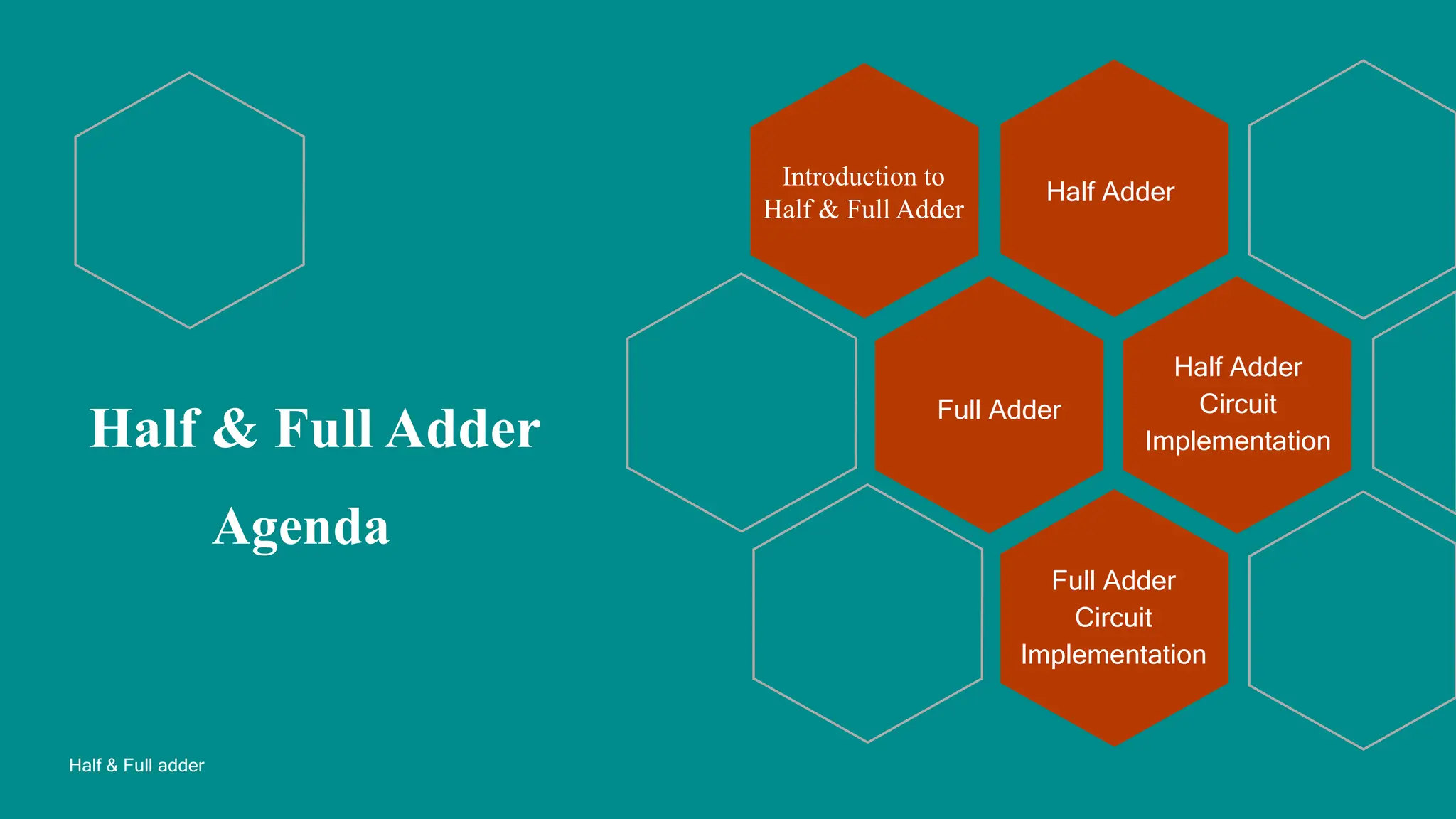
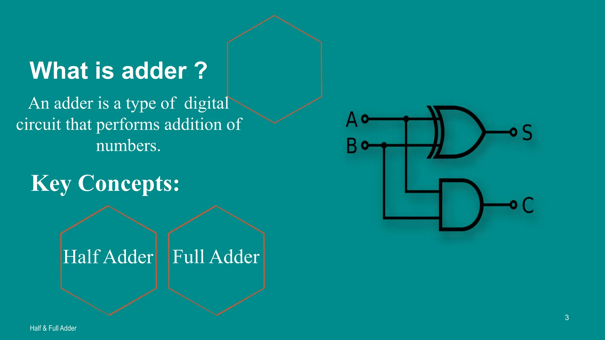
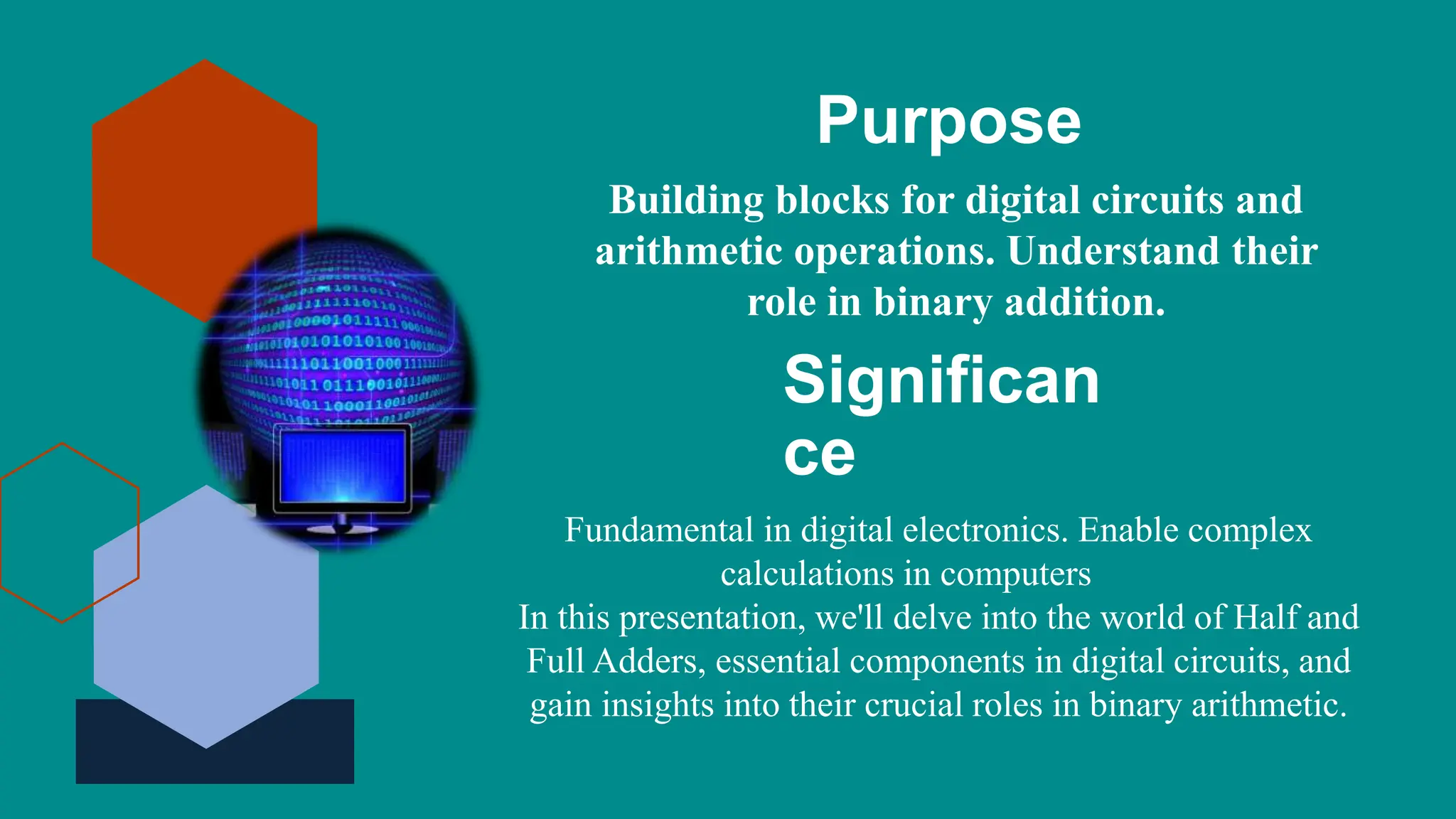
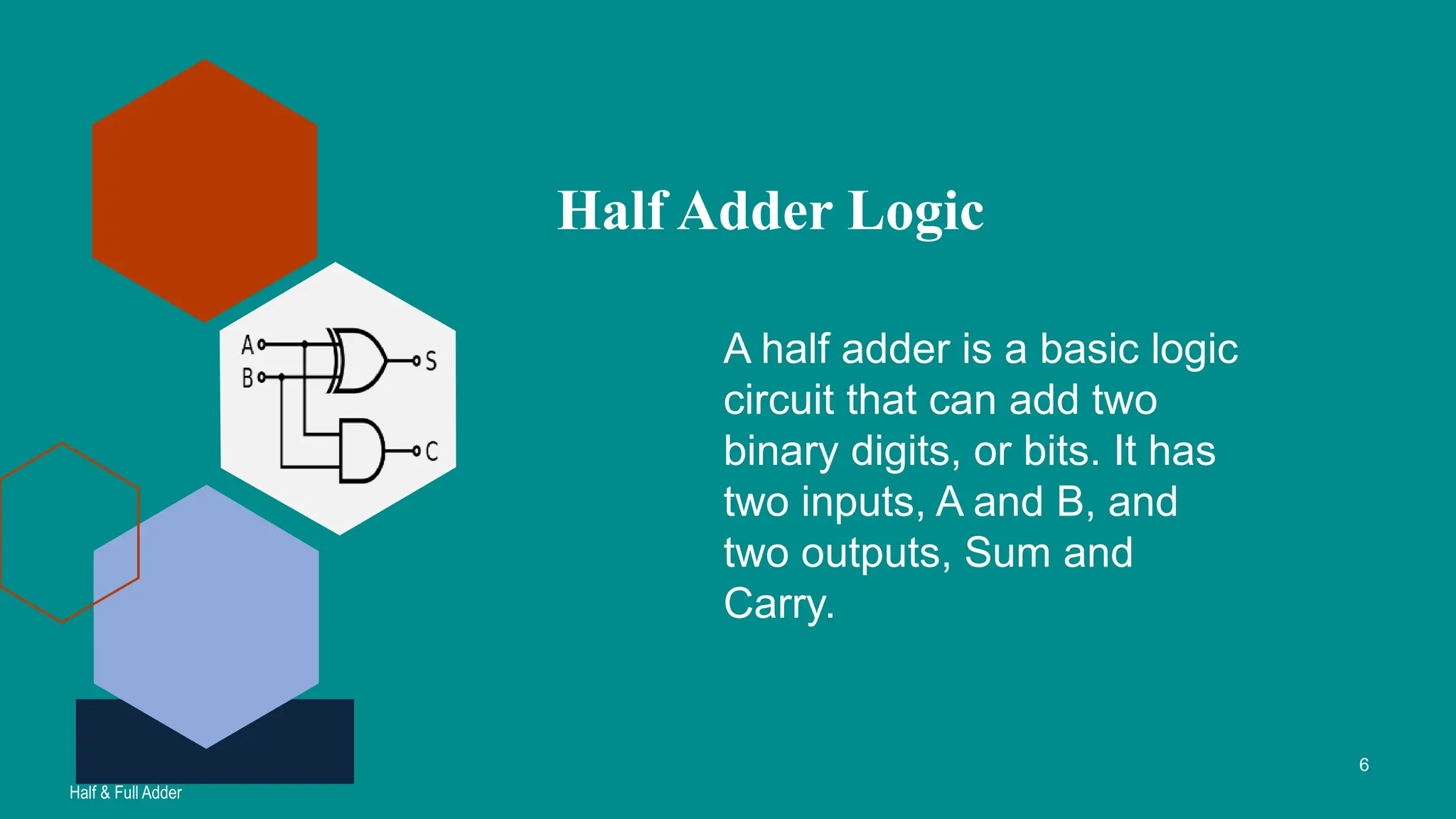
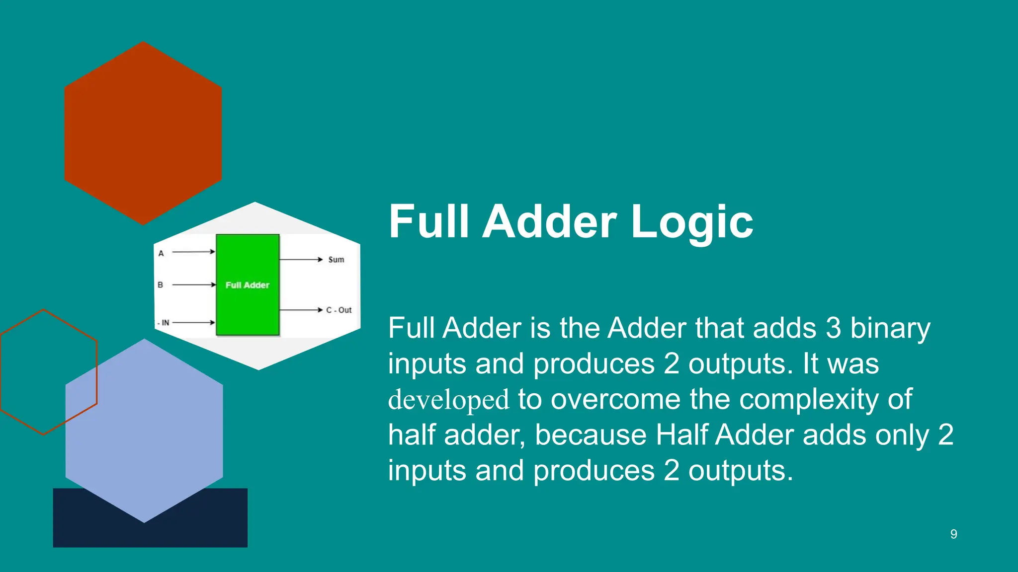
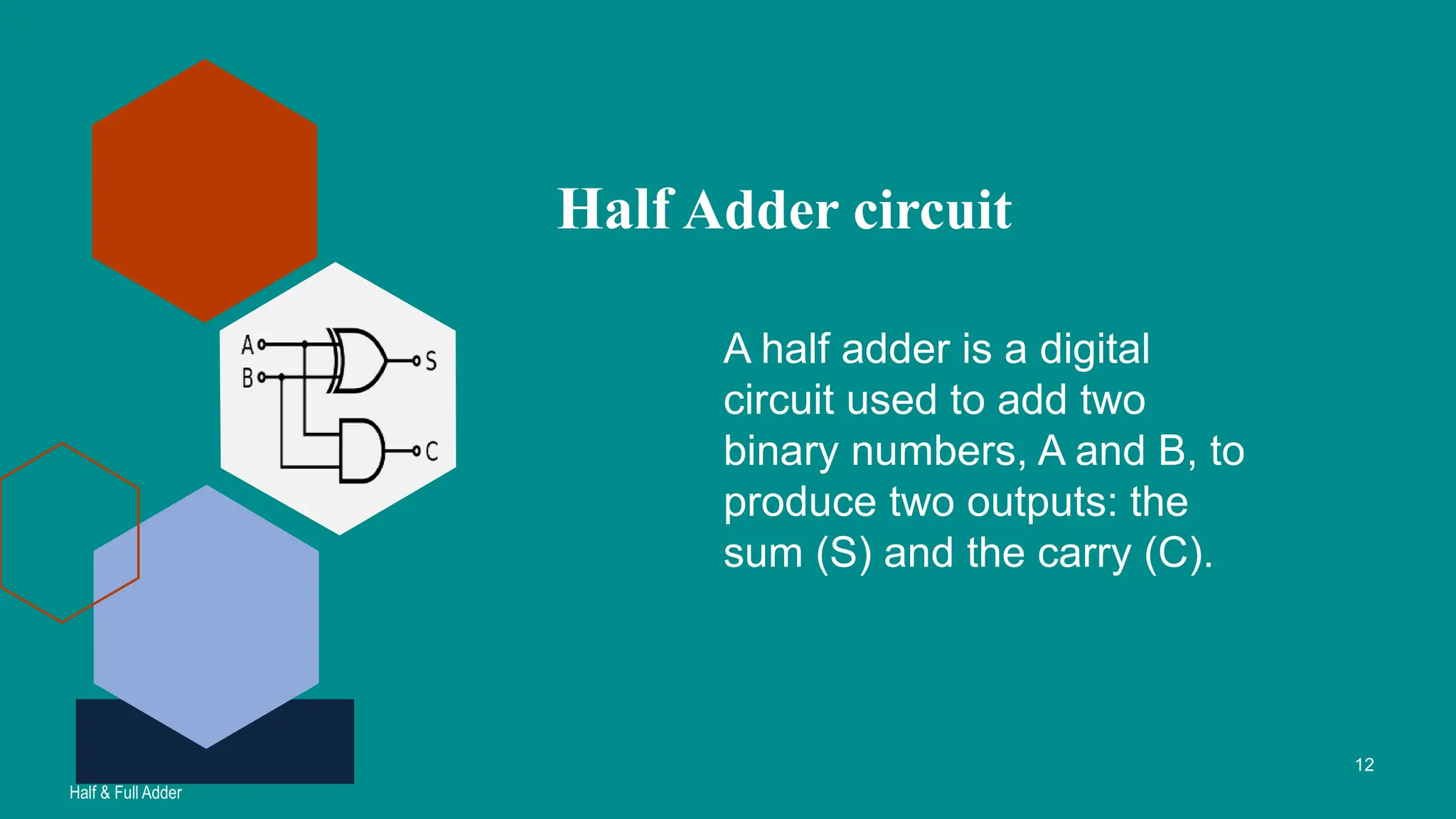
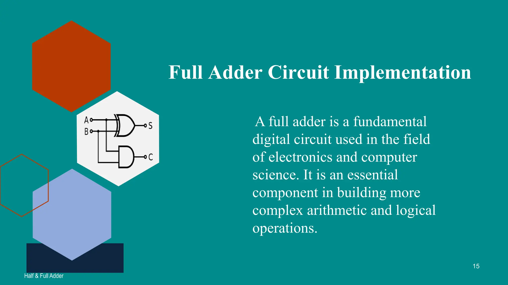
Agenda
Introduction to
Half & Full Adder
Half Adder
Full Adder
Half Adder
Circuit
Implementation
Full Adder
Circuit
Implementation
Half & Full adder
Half & Full Adder
Introduction to
Half & Full Adder
Presenter
Name : Rukaiya Akther Trisha
ID : 232-35-292
Key Concepts:
Half & Full Adder
3
What is adder ?
An adder is a type of digital
circuit that performs addition of
numbers.
Half Adder Full Adder
Purpose
Building blocks for digital circuits and
arithmetic operations. Understand their
role in binary addition.
Significan
ce
Fundamental in digital electronics. Enable complex
calculations in computers
In this presentation, we'll delve into the world of Half and
Full Adders, essential components in digital circuits, and
gain insights into their crucial roles in binary arithmetic.
Half Adder
Presenter
Name : Reduan Ahmad
ID : 232-35-016
A half adder is a basic logic
circuit that can add two
binary digits, or bits. It has
two inputs, A and B, and
two outputs, Sum and
Carry.
Half Adder Logic
Half & Full Adder
6
Truth Table
A B Carry Sum
0 0 0 0
0 1 0 1
1 0 0 1
1 1 1 0
Sum = A XOR B
Carry = AAND B
Full Adder
Presenter
Name : Abdullah Al Noman
ID : 232-35-003
Full Adder Logic
Full Adder is the Adder that adds 3 binary
inputs and produces 2 outputs. It was
developed to overcome the complexity of
half adder, because Half Adder adds only 2
inputs and produces 2 outputs.
9
Truth Table
A B Cin Carry Sum
0 0 0 0 0
0 0 1 1 0
0 1 0 1 0
0 1 1 0 1
1 0 0 1 0
1 0 1 0 1
1 0 0 0 1
1 0 1 1 1
Inputs Outputs
1. Half Adder Circuit
Presenter
Name : KM AHANAF RIAR KAIF
ID : 232-35-149
A half adder is a digital
circuit used to add two
binary numbers, A and B, to
produce two outputs: the
sum (S) and the carry (C).
Half Adder circuit
Half & Full Adder
12
The half adder circuit performs binary addition on
two single-bit binary numbers. The SUM output is
the least significant bit (LSB) of the result, while the
CARRY output is the most significant bit (MSB) of
the result, indicating whether there was a carry-over
from the addition of the two inputs.
Full Adder Circuit
Implementation
Presenter
Name : Mohammad Ali Nayeem
ID : 232-35-022
A full adder is a fundamental
digital circuit used in the field
of electronics and computer
science. It is an essential
component in building more
complex arithmetic and logical
operations.
Full Adder Circuit Implementation
Half & Full Adder
15
To build a full adder circuit, you will need the following
components:
Three input wires (A, B, C-in).
Two XOR gates.
Two AND gates.
One OR gate.
Two output wires (S, C-out).
Thank you
This Photo by
Unknown Author is

Half & Full Adder Adder Logic Circuit.pptx

  • 1.
    Agenda Introduction to Half &Full Adder Half Adder Full Adder Half Adder Circuit Implementation Full Adder Circuit Implementation Half & Full adder Half & Full Adder
  • 2.
    Introduction to Half &Full Adder Presenter Name : Rukaiya Akther Trisha ID : 232-35-292
  • 3.
    Key Concepts: Half &Full Adder 3 What is adder ? An adder is a type of digital circuit that performs addition of numbers. Half Adder Full Adder
  • 4.
    Purpose Building blocks fordigital circuits and arithmetic operations. Understand their role in binary addition. Significan ce Fundamental in digital electronics. Enable complex calculations in computers In this presentation, we'll delve into the world of Half and Full Adders, essential components in digital circuits, and gain insights into their crucial roles in binary arithmetic.
  • 5.
    Half Adder Presenter Name :Reduan Ahmad ID : 232-35-016
  • 6.
    A half adderis a basic logic circuit that can add two binary digits, or bits. It has two inputs, A and B, and two outputs, Sum and Carry. Half Adder Logic Half & Full Adder 6
  • 7.
    Truth Table A BCarry Sum 0 0 0 0 0 1 0 1 1 0 0 1 1 1 1 0 Sum = A XOR B Carry = AAND B
  • 8.
    Full Adder Presenter Name :Abdullah Al Noman ID : 232-35-003
  • 9.
    Full Adder Logic FullAdder is the Adder that adds 3 binary inputs and produces 2 outputs. It was developed to overcome the complexity of half adder, because Half Adder adds only 2 inputs and produces 2 outputs. 9
  • 10.
    Truth Table A BCin Carry Sum 0 0 0 0 0 0 0 1 1 0 0 1 0 1 0 0 1 1 0 1 1 0 0 1 0 1 0 1 0 1 1 0 0 0 1 1 0 1 1 1 Inputs Outputs
  • 11.
    1. Half AdderCircuit Presenter Name : KM AHANAF RIAR KAIF ID : 232-35-149
  • 12.
    A half adderis a digital circuit used to add two binary numbers, A and B, to produce two outputs: the sum (S) and the carry (C). Half Adder circuit Half & Full Adder 12
  • 13.
    The half addercircuit performs binary addition on two single-bit binary numbers. The SUM output is the least significant bit (LSB) of the result, while the CARRY output is the most significant bit (MSB) of the result, indicating whether there was a carry-over from the addition of the two inputs.
  • 14.
    Full Adder Circuit Implementation Presenter Name: Mohammad Ali Nayeem ID : 232-35-022
  • 15.
    A full adderis a fundamental digital circuit used in the field of electronics and computer science. It is an essential component in building more complex arithmetic and logical operations. Full Adder Circuit Implementation Half & Full Adder 15
  • 16.
    To build afull adder circuit, you will need the following components: Three input wires (A, B, C-in). Two XOR gates. Two AND gates. One OR gate. Two output wires (S, C-out).
  • 17.
    Thank you This Photoby Unknown Author is