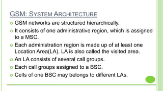
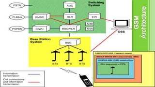
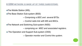
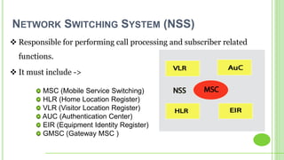
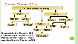
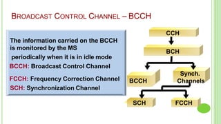
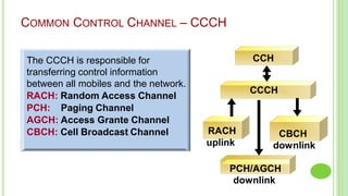
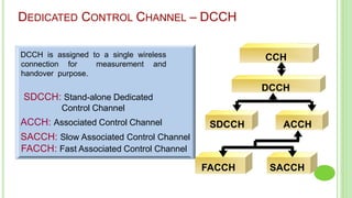
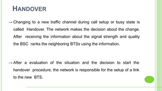
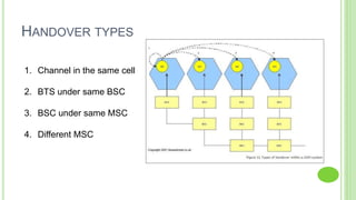
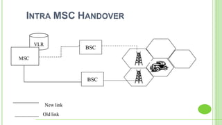
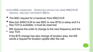
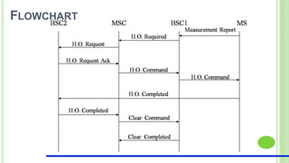
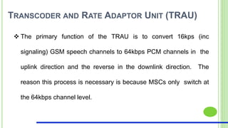
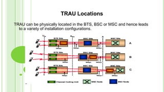
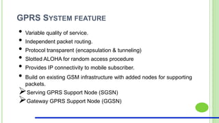
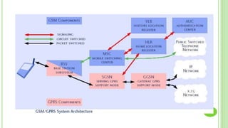
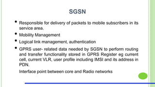
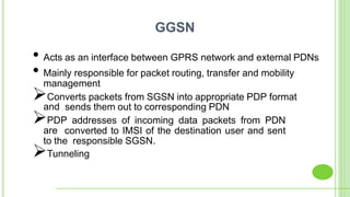
Global System for Mobile Communication
Second Generation technology
GSM ARCHITECTURE
GSM: SYSTEM ARCHITECTURE
 GSM networks are structured hierarchically.
 It consists of one administrative region, which is assigned
to a MSC.
 Each administration region is made up of at least one
Location Area(LA). LA is also called the visited area.
 An LA consists of several call groups.
 Each call groups assigned to a BSC.
 Cells of one BSC may belongs to different LAs.
A GSM NETWORK IS MADE UP OF THREE SUBSYSTEMS:
The Mobile Station (MS).
The Base Station Sub-system (BSS)
– Comprising a BSC and several BTSs.
– Control radio link with MS and BSCs.
The Network and Switching Sub-system (NSS)
– comprising an MSC and associated registers.
The Operation and Support Sub-system (OSS)
– Operator monitor and Control the system.
THE INTERFACES DEFINED BETWEEN EACH OF THESE SUB SYSTEMS INCLUDE:
'A' interface between NSS and BSS.
'Abis' interface between BSC and BTS (within the BSS).
'Um' air interface between the BSS and the MS.
‘SS7’ Interface for connection to other networks.
₪ IMEI (International Mobile Station Equipment Identity)
₪ IMSI (International Mobile Subscriber Identity)
₪ TMSI (Temporary Mobile Subscriber Identity)
₪ MSISDN (Mobile Subscriber *ISDN Number)
₪ MSRN (Mobile Station Roaming Number)
₪ LAI (Location Area Identity)
Mobile Station:
 The Mobile Station (MS) consists of the physical equipment used by a
. PLMN subscriber to connect to the network.
 Itcomprises the Mobile Equipment (ME) and the Subscriber Identity Module (SIM).
 Other Identities Include :-
Public Land Mobile Networks
*Integrated Service Digital Network
The IMSI identifies the subscriber within the GSM network while the MS ISDN is the actual
telephone number a caller (possibly in another network) uses to reach that person.
Security is provided by the use of an authentication key and by the transmission of a
temporary subscriber identity (TMSI) across the radio interface where possible to avoid
using the permanent IMSI identity.
The IMEI may be used to block certain types of equipment from accessing the network if
they are unsuitable and also to check for stolen equipment.
THE BSS COMPRISES:
oBase Station Controller (BSC)
o One or more Base Transceiver Stations (BTSs)
BTS contains:
→ Radio Transmitter/Receiver (TRX)
→ Signal processing and control equipment
→ Antennas and feeder cables
The purpose of the BTS is to:
• Provide radio access to the mobile stations.
• Manage the radio access aspects of the system.
BTS
• Allocates a channel for the duration of a call.
• Maintains the call.
• Monitors quality.
• Controls the power transmitted by the BTS or MS.
• Generates a handover to another cell when required.
BSC
NETWORK SWITCHING SYSTEM (NSS)
 Responsible for performing call processing and subscriber related
functions.
 It must include ->
MSC (Mobile Service Switching)
HLR (Home Location Register)
VLR (Visitor Location Register)
AUC (Authentication Center)
EIR (Equipment Identity Register)
GMSC (Gateway MSC )
MOBILE SERVICE SWITCHING CENTER - MSC
Call Processing.
Operations and Maintenance Support.
Interface Management.
Inter-network and Inter-working.
Billing.
HOME LOCATION REGISTER- HLR
Subscriber ID (IMSI and MSISDN).
Current subscriber VLR (current location).
Supplementary service information.
Subscriber Status (registered / deregistered)
Authentication key and AuC functionality.
VISITOR LOCATION REGISTER- VLR
Mobile Status (IMSI attached / detached / busy .)
Location Area Identity (LAI).
Temporary Mobile Subscriber Identity (TMSI).
Allocation and Roaming Number.
EQUIPMENT IDENTITY REGISTER- EIR
IMEI is checked in
White List
IMEI is checked in
Black/Grey List
EIR Focus on the .
. equipment , not the . .
subscriber!!!
IF NOT FOUND
OMC FUNCTIONAL ARCHITECTURE
CHANNEL ON WIRELESS INTERFACE
Part - 2
PHYSICAL CHANNEL AND LOGICAL CHANNEL
i
The physical channel is the medium over which the
information is carried: 200KHz and 0.577ms
The logical channel consists of the information carried
over the physical channels
0 1 2 3 4 5 6 7 0 1 2 3
Timeslot The information carried in one time
slot is called a “burst”
TDMA FRAME TDMA FRAME
TRAFFIC CHANNEL (TCH)
TCH/FS Full rate Speech Channel
TCH/HS Half rate Speech Channel
TCH/9.6 Data Channel 9.6kb/s
TCH/4.8 Data Channel 4.8kb/s
TCH/2.4 Data Channel 2.4Kb/s
TCH
Traffic Channels
Speech Data
TCH/HS
TCH/9.6 TCH/2.4
TCH/4.8
TCH/FS
TCH Traffic Channel
Broadcast Control Channel – BCCH
Common Control Channel – CCCH
Dedicated Control Channel – DCCH
Associated Control Channel – ACCH
CONTROL CHANNEL (CCH)
FCCHSCH
CCH (Control Channels)
DCCH
SDCCH
BCH
BCCH Synch. CH.ACCH
SACCHFACCH CCCH
RACH CBCH
PCH/AGCH
BCCH
CCH
BCH
Synch.
Channels
FCCH
The information carried on the BCCH
is monitored by the MS
periodically when it is in idle mode
BCCH: Broadcast Control Channel
FCCH: Frequency Correction Channel
SCH: Synchronization Channel
BROADCAST CONTROL CHANNEL – BCCH
SCH
CCH
CCCH
RACH
uplink
CBCH
downlink
PCH/AGCH
downlink
The CCCH is responsible for
transferring control information
between all mobiles and the network.
RACH: Random Access Channel
PCH: Paging Channel
AGCH: Access Grante Channel
CBCH: Cell Broadcast Channel
COMMON CONTROL CHANNEL – CCCH
CCH
DCCH
SDCCH
FACCH SACCH
DCCH is assigned to a single wireless
connection for measurement and
handover purpose.
SDCCH: Stand-alone Dedicated
Control Channel
ACCH: Associated Control Channel
SACCH: Slow Associated Control Channel
FACCH: Fast Associated Control Channel
ACCH
DEDICATED CONTROL CHANNEL – DCCH
HOW TO USE THESE CHANNELS?
MS UPDATION
LOCATION REGISTRATION
• When the mobile is turned on first time in the network, it has no
indications in its data about an old Location Area Identity.
• MS immediately inform the network and request for the Location
Update to the MSC/ VLR.
• After registration MSC/ VLR will consider the MS as active and marked
the MS as “attached”.
LOCATION UPDATE
PAGING
• A call to MS is routed to the MSC/ VLR and send a paging message
to the MS. This message is broadcast all over the Location Area
(LA), which means that all BTSs with in the LA will send a paging
message to the mobile.
• The MS, moving in the LA and listening to the CCCH information,
will hear the paging message and answer it immediately.
PAGING CAPACITY
› Paging capacity is the number of mobiles that can
be paged per second
› This depends on:
› CCCH configuration
› AGCH blocks reservation
› Type of paging message used
› Paging message takes 4 bursts (1 CCCH block)
› This can page up to 4 mobiles depending on the
message type used
CALL FROM MS (MOBILE TO PSTN)
MSC
Exch
PSTN
PLMN
VLR
CALL FROM MS OVERVIEW
• Mobile is active and idle, wants to set up a call
• User dial the number and press send, at first moment it sends on
RACH
• MSC/VLR assigns a dedicated channel
• If the calling MS is allowed to make a call MSC/VLR
acknowledges the access request
Depending on whether a fixed or a mobile subscriber is . . . .
called, number is analyzed directly in the MSC/VLR.
Call setup message is acknowledged as soon as the link is .
ready.
(MOBILEORIGINATED)
(MOBILETERMINATED)
CALL RELEASE
HANDOVERS
HANDOVER
→ Changing to a new traffic channel during call setup or busy state is
called Handover. The network makes the decision about the change.
After receiving the information about the signal strength and quality
the BSC ranks the neighboring BTSs using the information.
→ After a evaluation of the situation and the decision to start the
handover procedure, the network is responsible for the setup of a link
to the new BTS.
HANDOVER TYPES
1. Channel in the same cell
2. BTS under same BSC
3. BSC under same MSC
4. Different MSC
INTRA MSC HANDOVER
BSC
BSC
VLR
MSC
New link
Old link
INTRA MSC HANDOVER: HANDOVER WITHIN THE SAME MSC/VLR
SERVICE AREA BUT DIFFERENT BSCS.
•
•
• The BSC request for a handover from MSC/VLR
• New link (MSC/VLR to new BSC to new BTS) is setup and if a
free TCH is available, it must be reserved.
MS receives the order to change to the new frequency and the
new TCH.
If the BTS change has also change of location area, the MS
sends a request for location update after the call.
FLOWCHART
OTHER IMPORTANT UNITS
TRANSCODER AND RATE ADAPTOR UNIT (TRAU)
 The primary function of the TRAU is to convert 16kps (inc
signaling) GSM speech channels to 64kbps PCM channels in the
uplink direction and the reverse in the downlink direction. The
reason this process is necessary is because MSCs only switch at
the 64kbps channel level.
TRAU Locations
TRAU can be physically located in the BTS, BSC or MSC and hence leads
to a variety of installation configurations.
GATEWAY MSC (GMSC)
• Gateway MSC (GMSC) connects the PLMN with other networks and
the entry point for the mobile subscriber calls having the interrogation
facility. It has the function to obtain the information from the HLR
about the subscriber’s current location and reroute the calls
accordingly.
• In case of the network having only on MSC, the same MSC work as
the GMSC, while in the case having more than one MSC, one
dedicated MSC works as GMSC.
GPRS
PACKET SWITCHED SERVICE:
• Several users can share the same channel.
• Charges based on channel usage (actual usage of byte
transferred).
• Well suited for bursty traffic.
• Resource allocation done independently on UL and DL (good for
applications with asymmetrical bit rate)
• Dynamic allocation of resources
• Can multiplex traffic (voice, data, video).
2
Offered GPRS Traffic
10
9
8
7
6
5
4
3
2
1
0
TCH
Circuit Switched Traffic
6
4
2
0
8
10
12
14
TCH
GSM
capacity
6
8
10
12
14
0
2
4
SPEECH TRAFFIC LEAVES SOME CAPACITY FOR
packet data
GPRS SYSTEM FEATURE
• Variable quality of service.
• Independent packet routing.
• Protocol transparent (encapsulation & tunneling)
• Slotted ALOHA for random access procedure
• Provides IP connectivity to mobile subscriber.
• Build on existing GSM infrastructure with added nodes for supporting
packets.
Serving GPRS Support Node (SGSN)
Gateway GPRS Support Node (GGSN)
SGSN
• Responsible for delivery of packets to mobile subscribers in its
service area.
• Mobility Management
• Logical link management, authentication
• GPRS user- related data needed by SGSN to perform routing
and transfer functionality stored in GPRS Register eg current
cell, current VLR, user profile including IMSI and its address in
PDN.
Interface point between core and Radio networks
• Acts as an interface between GPRS network and external PDNs
• Mainly responsible for packet routing, transfer and mobility
management
Converts packets from SGSN into appropriate PDP format
and sends them out to corresponding PDN
PDP addresses of incoming data packets from PDN
are converted to IMSI of the destination user and sent
to the responsible SGSN.
Tunneling
GGSN
CONCLUSION
In GSM you use a wider variety of phones with your service, it
also allows you to take any GSM hardware and make it "your
phone" instantly, including the ability to carry your contacts right
on the SIM card.
GSM is a frontier technologies having some advantages and
disadvantages.
It depends upon the subscriber’s choice which technology best
suits their needs.
Gsm

Gsm

  • 1.
    Global System forMobile Communication Second Generation technology
  • 2.
  • 3.
    GSM: SYSTEM ARCHITECTURE GSM networks are structured hierarchically.  It consists of one administrative region, which is assigned to a MSC.  Each administration region is made up of at least one Location Area(LA). LA is also called the visited area.  An LA consists of several call groups.  Each call groups assigned to a BSC.  Cells of one BSC may belongs to different LAs.
  • 5.
    A GSM NETWORKIS MADE UP OF THREE SUBSYSTEMS: The Mobile Station (MS). The Base Station Sub-system (BSS) – Comprising a BSC and several BTSs. – Control radio link with MS and BSCs. The Network and Switching Sub-system (NSS) – comprising an MSC and associated registers. The Operation and Support Sub-system (OSS) – Operator monitor and Control the system.
  • 6.
    THE INTERFACES DEFINEDBETWEEN EACH OF THESE SUB SYSTEMS INCLUDE: 'A' interface between NSS and BSS. 'Abis' interface between BSC and BTS (within the BSS). 'Um' air interface between the BSS and the MS. ‘SS7’ Interface for connection to other networks.
  • 7.
    ₪ IMEI (InternationalMobile Station Equipment Identity) ₪ IMSI (International Mobile Subscriber Identity) ₪ TMSI (Temporary Mobile Subscriber Identity) ₪ MSISDN (Mobile Subscriber *ISDN Number) ₪ MSRN (Mobile Station Roaming Number) ₪ LAI (Location Area Identity) Mobile Station:  The Mobile Station (MS) consists of the physical equipment used by a . PLMN subscriber to connect to the network.  Itcomprises the Mobile Equipment (ME) and the Subscriber Identity Module (SIM).  Other Identities Include :- Public Land Mobile Networks *Integrated Service Digital Network
  • 8.
    The IMSI identifiesthe subscriber within the GSM network while the MS ISDN is the actual telephone number a caller (possibly in another network) uses to reach that person. Security is provided by the use of an authentication key and by the transmission of a temporary subscriber identity (TMSI) across the radio interface where possible to avoid using the permanent IMSI identity. The IMEI may be used to block certain types of equipment from accessing the network if they are unsuitable and also to check for stolen equipment.
  • 9.
    THE BSS COMPRISES: oBaseStation Controller (BSC) o One or more Base Transceiver Stations (BTSs) BTS contains: → Radio Transmitter/Receiver (TRX) → Signal processing and control equipment → Antennas and feeder cables The purpose of the BTS is to: • Provide radio access to the mobile stations. • Manage the radio access aspects of the system. BTS
  • 10.
    • Allocates achannel for the duration of a call. • Maintains the call. • Monitors quality. • Controls the power transmitted by the BTS or MS. • Generates a handover to another cell when required. BSC
  • 11.
    NETWORK SWITCHING SYSTEM(NSS)  Responsible for performing call processing and subscriber related functions.  It must include -> MSC (Mobile Service Switching) HLR (Home Location Register) VLR (Visitor Location Register) AUC (Authentication Center) EIR (Equipment Identity Register) GMSC (Gateway MSC )
  • 12.
    MOBILE SERVICE SWITCHINGCENTER - MSC Call Processing. Operations and Maintenance Support. Interface Management. Inter-network and Inter-working. Billing.
  • 13.
    HOME LOCATION REGISTER-HLR Subscriber ID (IMSI and MSISDN). Current subscriber VLR (current location). Supplementary service information. Subscriber Status (registered / deregistered) Authentication key and AuC functionality.
  • 14.
    VISITOR LOCATION REGISTER-VLR Mobile Status (IMSI attached / detached / busy .) Location Area Identity (LAI). Temporary Mobile Subscriber Identity (TMSI). Allocation and Roaming Number.
  • 15.
    EQUIPMENT IDENTITY REGISTER-EIR IMEI is checked in White List IMEI is checked in Black/Grey List EIR Focus on the . . equipment , not the . . subscriber!!! IF NOT FOUND
  • 16.
  • 17.
    CHANNEL ON WIRELESSINTERFACE Part - 2
  • 18.
    PHYSICAL CHANNEL ANDLOGICAL CHANNEL i The physical channel is the medium over which the information is carried: 200KHz and 0.577ms The logical channel consists of the information carried over the physical channels 0 1 2 3 4 5 6 7 0 1 2 3 Timeslot The information carried in one time slot is called a “burst” TDMA FRAME TDMA FRAME
  • 20.
    TRAFFIC CHANNEL (TCH) TCH/FSFull rate Speech Channel TCH/HS Half rate Speech Channel TCH/9.6 Data Channel 9.6kb/s TCH/4.8 Data Channel 4.8kb/s TCH/2.4 Data Channel 2.4Kb/s TCH Traffic Channels Speech Data TCH/HS TCH/9.6 TCH/2.4 TCH/4.8 TCH/FS TCH Traffic Channel
  • 21.
    Broadcast Control Channel– BCCH Common Control Channel – CCCH Dedicated Control Channel – DCCH Associated Control Channel – ACCH CONTROL CHANNEL (CCH) FCCHSCH CCH (Control Channels) DCCH SDCCH BCH BCCH Synch. CH.ACCH SACCHFACCH CCCH RACH CBCH PCH/AGCH
  • 22.
    BCCH CCH BCH Synch. Channels FCCH The information carriedon the BCCH is monitored by the MS periodically when it is in idle mode BCCH: Broadcast Control Channel FCCH: Frequency Correction Channel SCH: Synchronization Channel BROADCAST CONTROL CHANNEL – BCCH SCH
  • 23.
    CCH CCCH RACH uplink CBCH downlink PCH/AGCH downlink The CCCH isresponsible for transferring control information between all mobiles and the network. RACH: Random Access Channel PCH: Paging Channel AGCH: Access Grante Channel CBCH: Cell Broadcast Channel COMMON CONTROL CHANNEL – CCCH
  • 24.
    CCH DCCH SDCCH FACCH SACCH DCCH isassigned to a single wireless connection for measurement and handover purpose. SDCCH: Stand-alone Dedicated Control Channel ACCH: Associated Control Channel SACCH: Slow Associated Control Channel FACCH: Fast Associated Control Channel ACCH DEDICATED CONTROL CHANNEL – DCCH
  • 25.
    HOW TO USETHESE CHANNELS?
  • 26.
  • 27.
    LOCATION REGISTRATION • Whenthe mobile is turned on first time in the network, it has no indications in its data about an old Location Area Identity. • MS immediately inform the network and request for the Location Update to the MSC/ VLR. • After registration MSC/ VLR will consider the MS as active and marked the MS as “attached”.
  • 28.
  • 29.
    PAGING • A callto MS is routed to the MSC/ VLR and send a paging message to the MS. This message is broadcast all over the Location Area (LA), which means that all BTSs with in the LA will send a paging message to the mobile. • The MS, moving in the LA and listening to the CCCH information, will hear the paging message and answer it immediately.
  • 30.
    PAGING CAPACITY › Pagingcapacity is the number of mobiles that can be paged per second › This depends on: › CCCH configuration › AGCH blocks reservation › Type of paging message used › Paging message takes 4 bursts (1 CCCH block) › This can page up to 4 mobiles depending on the message type used
  • 31.
    CALL FROM MS(MOBILE TO PSTN) MSC Exch PSTN PLMN VLR
  • 32.
    CALL FROM MSOVERVIEW • Mobile is active and idle, wants to set up a call • User dial the number and press send, at first moment it sends on RACH • MSC/VLR assigns a dedicated channel • If the calling MS is allowed to make a call MSC/VLR acknowledges the access request Depending on whether a fixed or a mobile subscriber is . . . . called, number is analyzed directly in the MSC/VLR. Call setup message is acknowledged as soon as the link is . ready.
  • 33.
  • 34.
  • 35.
  • 36.
  • 37.
    HANDOVER → Changing toa new traffic channel during call setup or busy state is called Handover. The network makes the decision about the change. After receiving the information about the signal strength and quality the BSC ranks the neighboring BTSs using the information. → After a evaluation of the situation and the decision to start the handover procedure, the network is responsible for the setup of a link to the new BTS.
  • 38.
    HANDOVER TYPES 1. Channelin the same cell 2. BTS under same BSC 3. BSC under same MSC 4. Different MSC
  • 39.
  • 40.
    INTRA MSC HANDOVER:HANDOVER WITHIN THE SAME MSC/VLR SERVICE AREA BUT DIFFERENT BSCS. • • • The BSC request for a handover from MSC/VLR • New link (MSC/VLR to new BSC to new BTS) is setup and if a free TCH is available, it must be reserved. MS receives the order to change to the new frequency and the new TCH. If the BTS change has also change of location area, the MS sends a request for location update after the call.
  • 41.
  • 42.
  • 43.
    TRANSCODER AND RATEADAPTOR UNIT (TRAU)  The primary function of the TRAU is to convert 16kps (inc signaling) GSM speech channels to 64kbps PCM channels in the uplink direction and the reverse in the downlink direction. The reason this process is necessary is because MSCs only switch at the 64kbps channel level.
  • 44.
    TRAU Locations TRAU canbe physically located in the BTS, BSC or MSC and hence leads to a variety of installation configurations.
  • 45.
    GATEWAY MSC (GMSC) •Gateway MSC (GMSC) connects the PLMN with other networks and the entry point for the mobile subscriber calls having the interrogation facility. It has the function to obtain the information from the HLR about the subscriber’s current location and reroute the calls accordingly. • In case of the network having only on MSC, the same MSC work as the GMSC, while in the case having more than one MSC, one dedicated MSC works as GMSC.
  • 47.
  • 48.
    PACKET SWITCHED SERVICE: •Several users can share the same channel. • Charges based on channel usage (actual usage of byte transferred). • Well suited for bursty traffic. • Resource allocation done independently on UL and DL (good for applications with asymmetrical bit rate) • Dynamic allocation of resources • Can multiplex traffic (voice, data, video).
  • 49.
    2 Offered GPRS Traffic 10 9 8 7 6 5 4 3 2 1 0 TCH CircuitSwitched Traffic 6 4 2 0 8 10 12 14 TCH GSM capacity 6 8 10 12 14 0 2 4 SPEECH TRAFFIC LEAVES SOME CAPACITY FOR packet data
  • 50.
    GPRS SYSTEM FEATURE •Variable quality of service. • Independent packet routing. • Protocol transparent (encapsulation & tunneling) • Slotted ALOHA for random access procedure • Provides IP connectivity to mobile subscriber. • Build on existing GSM infrastructure with added nodes for supporting packets. Serving GPRS Support Node (SGSN) Gateway GPRS Support Node (GGSN)
  • 52.
    SGSN • Responsible fordelivery of packets to mobile subscribers in its service area. • Mobility Management • Logical link management, authentication • GPRS user- related data needed by SGSN to perform routing and transfer functionality stored in GPRS Register eg current cell, current VLR, user profile including IMSI and its address in PDN. Interface point between core and Radio networks
  • 53.
    • Acts asan interface between GPRS network and external PDNs • Mainly responsible for packet routing, transfer and mobility management Converts packets from SGSN into appropriate PDP format and sends them out to corresponding PDN PDP addresses of incoming data packets from PDN are converted to IMSI of the destination user and sent to the responsible SGSN. Tunneling GGSN
  • 54.
    CONCLUSION In GSM youuse a wider variety of phones with your service, it also allows you to take any GSM hardware and make it "your phone" instantly, including the ability to carry your contacts right on the SIM card. GSM is a frontier technologies having some advantages and disadvantages. It depends upon the subscriber’s choice which technology best suits their needs.