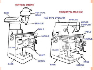
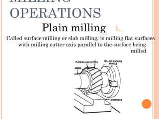
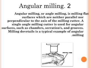
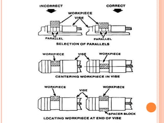
By: Saumya Ranjan BehuraBy: Saumya Ranjan Behura
 Milling machine unlike lathes they require
more power than hand driven – lathes.
Milling is the process of machining flat , curved,
or irregular surfaces by feeding the work piece
against a rotating cutter containing a number of
cutting edges.
THANK YOU SO MUCH
1. Vertical milling machines.
2. Horizontal milling machines.
 These machine also classified as:
Knee-type, Ram-type, manufacturing or bed type,
and planer-type.
 The universal milling machine:
A more complex form of the milling machine
The table of universal milling machine can be
swiveled through angle (up to 45 in either
direction).
 The universal milling machine can be fitted with
various attachments such as :
 The indexing fixture, rotary table, slotting and
rack cutting attachments and various special
fixtures.
The universal milling machine may be vertical
or horizontal machines.
The main components of these machines:
1.Ram
2.Spindle
3.Table
4.Saddle
5.Knee
6.Column
7.screw
FEEDING MECHANISM
SPECIFICATION OF THE MACHINE
Working surface 49 1/4” x 11” (1250 x 280mm)
Number of T slots 3” x 5/8” (3 x 16mm)
Distance between T slots 2 1/2” (63mm)
Table Swivel +/- 45°
Tabl
e
Transverse
Automatic Longitudinal 33 1/2” (851mm)
Automatic Cross 12” (290mm)
Automatic Vertical 18 3/4” (475mm)
Distance From Spindle to Over arm. 5 3/4” (147mm)
Feeds
Horizontal spindle
Number of Feeds Cont. Variable Speed
Longitudinal and Cross
Feed
0 + 51 3/16” (0 + 1300mm)
Vertical Feed 0 + 15 3/8” (0 + 390mm)
Spindle Taper #40
Main Spindle Diameter 3 1/2” (88.88mm)
Arbor Milling Diameter 1” (22mm)
Number of Speeds Variable Speed
Speed Range at 50Hz 35 - 1800 RPM
Speed Range at 60Hz 42 - 2160 (±10%) RPM
Main motor
Coolant system
weight
Main Spindle 5.5 HP
Working Feeds - Quick
Traverse
2 HP
Coolant Pump 0.12 HP
Approximate Net Weight 1800 kg
Maximum Weight Over the
Table
300 kg
MILLING
OPERATIONS
1.Plain milling
Called surface milling or slab milling, is milling flat surfaces
with milling cutter axis parallel to the surface being
milled
2.Angular milling
Angular milling, or angle milling, is milling flat
surfaces which are neither parallel nor
perpendicular to the axis of the milling cutter. A
single angle milling cutter is used for angular
surfaces, such as chamfers, serration's, and grooves.
Milling dovetails is a typical example of angular
milling.
3.Milling dovetails
The usual angle of cutter is 45° 50°, 55°, or 60° based on
common dovetail designs
4.Straddle Milling
When two or more parallel vertical surfaces are
machined at a single cut, the operation is called
straddle milling. Straddle milling is accomplished by
mounting two side milling cutters on the same arbor,
set apart at an exact spacing. Two sides of the work
piece are machined simultaneously and final width
dimensions are exactly controlled. Straddle milling
has many useful applications in production
machining.
5.Milling Hexagon
The work piece is usually mounted between centers in
the indexing fixture or mounted vertically in a swivel
vise. The two side milling cutters are separated by
spacers, washers, and shims so that the distance
between the cutting teeth of each cutter is exactly
equal to the width of the work piece area required.
6.Face milling
Face milling is the milling of surfaces that are
perpendicular to the cutter axis. Face milling
produces flat surfaces and machines work to the
required length. In face milling, the feed can be either
horizontal or vertical.
7.Gang Milling
which two or more milling cutters are mounted on the
same arbor and used when cutting horizontal
surfaces.
All cutters may perform the same type of operation or
each cutter may perform a different type of operation.
8.Form Milling.
IS the process of machining
special contours composed of
Curved and straight lines , or
Entirely of curves, at a single cut.
The more common form milling
operations involve milling
half-round recesses and beads
and quarter-round radii on
Work piece
9.Fly cutting
Fly cutting is one of the most versatile milling
operations. It is done with a single- point cutting
tool shaped like a lathe tool bit. It is held and rotated
by a fly cutter arbor . formed cutters are expensive
And usually suitable only for one particular job
10.Gear cutting
Is enough of the broken gear to grind the cutting tool to
the proper shape. It can also be used in the cutting of
splines and standard and special forms.
11.Keyway Milling
The type of key and corresponding keyway to be used
depends upon the class of work for which it is
intended.
Types of keys:
1.Woodruff key
2.Square - end machine keys
3.Round - end machine keys
1.Wood ruff key
The Woodruff keys are semi cylindrical in shape and
are manufactured in various diameters and width
2.Square - end machine key
Square-ends machine keys are square or rectangular in
section and several times as long as they are wide.
For the purpose of interchangeability and
standardization, these keys are usually
proportioned with relation to the shaft diameter
3.Round – end- machine key
The round-ends machine keys are square in section with
either one or both ends rounded off. These keys are
the same as square-ends machine keys in
measurements.
MILLING CUTTER USED
FOR MILLING KEYWAYS
12.T slot milling
Cutting T-slots in a work piece holding device is a
typical milling operation. The size of the T-slots
depends upon the size of the T-slot bolts which will be
used. Dimensions of T-slots and T-slot bolts are
standardized for specific bolt diameters.
Selection of milling cutter:
The T-slot milling cutter is then
used to cut the head space to the
prescribed dimensions.
13.Sawing and parting
Metal slitting saw milling cutters are used to part stock
on a milling machine . The work piece is being fed
against the rotation of the cutter.
14.Gear cutting
Gear teeth are cut on the milling machine using formed
milling cutters called involute gear cutters. These
cutters are manufactured in many pitch sizes and
shapes for different numbers of teeth.
15.Drilling
The milling machine may be used effectively for drilling,
since accurate location of the hole may be secured by
means of the feed screw graduations. Spacing holes in
a circular path, such as the holes in an index plate,
may be accomplished by indexing with the index head
positioned vertically.
16.Boring
Various types of boring tool holders may be used for
boring on the milling machine, the boring tools being
provided with either straight shanks to be held in
chucks and holders or taper shanks to fit collets and
adapters. The two attachments most commonly used
for boring are the fly cutter arbor and the offset
boring head.
The single-edge cutting tool used for boring on the
milling machine is the same as a lathe cutter bit.
Cutting speeds, feeds, and depth of cut should be the
same as that prescribed for lathe operations.
TOOL HOLDING
Methods of cutters fixation:
Types of fixation
1.Arbors
Arbors are supplied with one of
three tapers to fit the milling
machine spindle:
.1 1.Standard milling machine arbor
The standard milling machine arbor has a tapered,
cylindrical shaft with a standard milling taper on the
driving end and a threaded portion on the opposite
end to receive the arbor nut.
.1 2.sc
ew arbor
Screw arbors are used to hold small cutters that have
threaded holes.
.1 3.The slitting saw milling cutter
arbor
is a short arbor having two flanges between which the
milling cutter is secured by tightening
a clamping nut.
.1 4.the shell end milling cutting arbor
has a bore in the end in which shell end milling cutters
fit and are locked in place by means of a cap screw.
.1 5.the fly cutter arbor
is used to support a single-edge lathe, shaper,
Or planer cutter bit for boring and gear cutting
operations on the milling machine.
2.Collets
Collets is a form of a sleeve bushing for reducing the
size of the hole in the milling machine spindle so that
small shank tools can be fitted into large spindle
recesses.
3.Chuck adapter
A chuck adapter is used to
attach chucks to milling
machines having a standard
spindle end
4.Spindle adapter
A spindle adapter is a form of collets having a
standardized spindle end.
5.Quick - change tooling
The quick-change adapter mounted on the spindle nose
is used to speed up tool changing.
Tool changing with this system allows you to set up a
number of milling operations such as drilling, end
milling, and boring without changing the Set up of the
part being machined.
MOUNTING WORK
PIECES
1.Clamping Workpieces to the Table.
2.Clamping a Workpiece to the Angle Plate.
3.Clamping Workpieces in Fixtures.
4.Holding Workpieces between Centers.
5.Holding Workpieces in a Chuck.
6.Holding Workpieces in the Vise.
Miling machine

Miling machine

  • 1.
    By: Saumya RanjanBehuraBy: Saumya Ranjan Behura
  • 2.
     Milling machineunlike lathes they require more power than hand driven – lathes. Milling is the process of machining flat , curved, or irregular surfaces by feeding the work piece against a rotating cutter containing a number of cutting edges.
  • 3.
  • 4.
    1. Vertical millingmachines. 2. Horizontal milling machines.  These machine also classified as: Knee-type, Ram-type, manufacturing or bed type, and planer-type.
  • 5.
     The universalmilling machine: A more complex form of the milling machine The table of universal milling machine can be swiveled through angle (up to 45 in either direction).  The universal milling machine can be fitted with various attachments such as :  The indexing fixture, rotary table, slotting and rack cutting attachments and various special fixtures.
  • 6.
    The universal millingmachine may be vertical or horizontal machines. The main components of these machines: 1.Ram 2.Spindle 3.Table 4.Saddle 5.Knee 6.Column 7.screw
  • 8.
  • 10.
    SPECIFICATION OF THEMACHINE Working surface 49 1/4” x 11” (1250 x 280mm) Number of T slots 3” x 5/8” (3 x 16mm) Distance between T slots 2 1/2” (63mm) Table Swivel +/- 45° Tabl e Transverse Automatic Longitudinal 33 1/2” (851mm) Automatic Cross 12” (290mm) Automatic Vertical 18 3/4” (475mm) Distance From Spindle to Over arm. 5 3/4” (147mm)
  • 11.
    Feeds Horizontal spindle Number ofFeeds Cont. Variable Speed Longitudinal and Cross Feed 0 + 51 3/16” (0 + 1300mm) Vertical Feed 0 + 15 3/8” (0 + 390mm) Spindle Taper #40 Main Spindle Diameter 3 1/2” (88.88mm) Arbor Milling Diameter 1” (22mm) Number of Speeds Variable Speed Speed Range at 50Hz 35 - 1800 RPM Speed Range at 60Hz 42 - 2160 (±10%) RPM
  • 12.
    Main motor Coolant system weight MainSpindle 5.5 HP Working Feeds - Quick Traverse 2 HP Coolant Pump 0.12 HP Approximate Net Weight 1800 kg Maximum Weight Over the Table 300 kg
  • 13.
    MILLING OPERATIONS 1.Plain milling Called surfacemilling or slab milling, is milling flat surfaces with milling cutter axis parallel to the surface being milled
  • 14.
    2.Angular milling Angular milling,or angle milling, is milling flat surfaces which are neither parallel nor perpendicular to the axis of the milling cutter. A single angle milling cutter is used for angular surfaces, such as chamfers, serration's, and grooves. Milling dovetails is a typical example of angular milling.
  • 15.
    3.Milling dovetails The usualangle of cutter is 45° 50°, 55°, or 60° based on common dovetail designs 4.Straddle Milling When two or more parallel vertical surfaces are machined at a single cut, the operation is called straddle milling. Straddle milling is accomplished by mounting two side milling cutters on the same arbor, set apart at an exact spacing. Two sides of the work piece are machined simultaneously and final width dimensions are exactly controlled. Straddle milling has many useful applications in production machining.
  • 16.
    5.Milling Hexagon The workpiece is usually mounted between centers in the indexing fixture or mounted vertically in a swivel vise. The two side milling cutters are separated by spacers, washers, and shims so that the distance between the cutting teeth of each cutter is exactly equal to the width of the work piece area required.
  • 17.
    6.Face milling Face millingis the milling of surfaces that are perpendicular to the cutter axis. Face milling produces flat surfaces and machines work to the required length. In face milling, the feed can be either horizontal or vertical.
  • 18.
    7.Gang Milling which twoor more milling cutters are mounted on the same arbor and used when cutting horizontal surfaces. All cutters may perform the same type of operation or each cutter may perform a different type of operation.
  • 19.
    8.Form Milling. IS theprocess of machining special contours composed of Curved and straight lines , or Entirely of curves, at a single cut. The more common form milling operations involve milling half-round recesses and beads and quarter-round radii on Work piece
  • 20.
    9.Fly cutting Fly cuttingis one of the most versatile milling operations. It is done with a single- point cutting tool shaped like a lathe tool bit. It is held and rotated by a fly cutter arbor . formed cutters are expensive And usually suitable only for one particular job
  • 21.
    10.Gear cutting Is enoughof the broken gear to grind the cutting tool to the proper shape. It can also be used in the cutting of splines and standard and special forms. 11.Keyway Milling The type of key and corresponding keyway to be used depends upon the class of work for which it is intended. Types of keys: 1.Woodruff key 2.Square - end machine keys 3.Round - end machine keys
  • 22.
    1.Wood ruff key TheWoodruff keys are semi cylindrical in shape and are manufactured in various diameters and width 2.Square - end machine key Square-ends machine keys are square or rectangular in section and several times as long as they are wide. For the purpose of interchangeability and standardization, these keys are usually proportioned with relation to the shaft diameter
  • 23.
    3.Round – end-machine key The round-ends machine keys are square in section with either one or both ends rounded off. These keys are the same as square-ends machine keys in measurements.
  • 24.
    MILLING CUTTER USED FORMILLING KEYWAYS
  • 25.
    12.T slot milling CuttingT-slots in a work piece holding device is a typical milling operation. The size of the T-slots depends upon the size of the T-slot bolts which will be used. Dimensions of T-slots and T-slot bolts are standardized for specific bolt diameters. Selection of milling cutter: The T-slot milling cutter is then used to cut the head space to the prescribed dimensions.
  • 26.
    13.Sawing and parting Metalslitting saw milling cutters are used to part stock on a milling machine . The work piece is being fed against the rotation of the cutter.
  • 27.
    14.Gear cutting Gear teethare cut on the milling machine using formed milling cutters called involute gear cutters. These cutters are manufactured in many pitch sizes and shapes for different numbers of teeth. 15.Drilling The milling machine may be used effectively for drilling, since accurate location of the hole may be secured by means of the feed screw graduations. Spacing holes in a circular path, such as the holes in an index plate, may be accomplished by indexing with the index head positioned vertically.
  • 28.
    16.Boring Various types ofboring tool holders may be used for boring on the milling machine, the boring tools being provided with either straight shanks to be held in chucks and holders or taper shanks to fit collets and adapters. The two attachments most commonly used for boring are the fly cutter arbor and the offset boring head. The single-edge cutting tool used for boring on the milling machine is the same as a lathe cutter bit. Cutting speeds, feeds, and depth of cut should be the same as that prescribed for lathe operations.
  • 29.
    TOOL HOLDING Methods ofcutters fixation: Types of fixation 1.Arbors
  • 30.
    Arbors are suppliedwith one of three tapers to fit the milling machine spindle: .1 1.Standard milling machine arbor The standard milling machine arbor has a tapered, cylindrical shaft with a standard milling taper on the driving end and a threaded portion on the opposite end to receive the arbor nut.
  • 31.
    .1 2.sc ew arbor Screwarbors are used to hold small cutters that have threaded holes. .1 3.The slitting saw milling cutter arbor is a short arbor having two flanges between which the milling cutter is secured by tightening a clamping nut.
  • 32.
    .1 4.the shellend milling cutting arbor has a bore in the end in which shell end milling cutters fit and are locked in place by means of a cap screw. .1 5.the fly cutter arbor is used to support a single-edge lathe, shaper, Or planer cutter bit for boring and gear cutting operations on the milling machine.
  • 33.
    2.Collets Collets is aform of a sleeve bushing for reducing the size of the hole in the milling machine spindle so that small shank tools can be fitted into large spindle recesses. 3.Chuck adapter A chuck adapter is used to attach chucks to milling machines having a standard spindle end
  • 34.
    4.Spindle adapter A spindleadapter is a form of collets having a standardized spindle end.
  • 35.
    5.Quick - changetooling The quick-change adapter mounted on the spindle nose is used to speed up tool changing. Tool changing with this system allows you to set up a number of milling operations such as drilling, end milling, and boring without changing the Set up of the part being machined.
  • 36.
    MOUNTING WORK PIECES 1.Clamping Workpiecesto the Table. 2.Clamping a Workpiece to the Angle Plate. 3.Clamping Workpieces in Fixtures. 4.Holding Workpieces between Centers. 5.Holding Workpieces in a Chuck. 6.Holding Workpieces in the Vise.