Downloaded 116 times


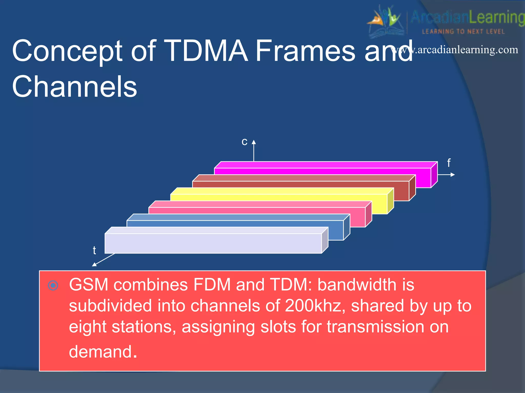

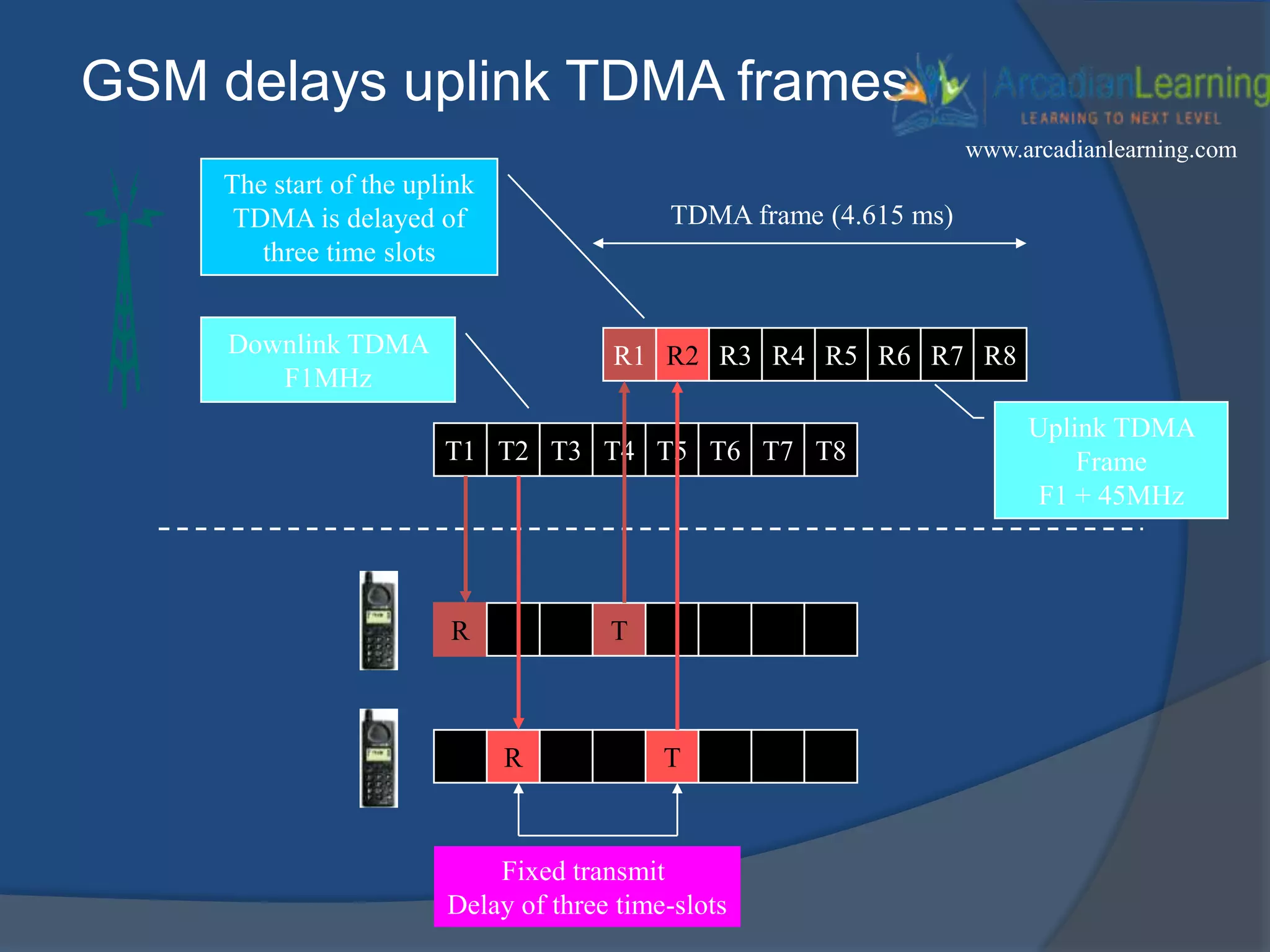
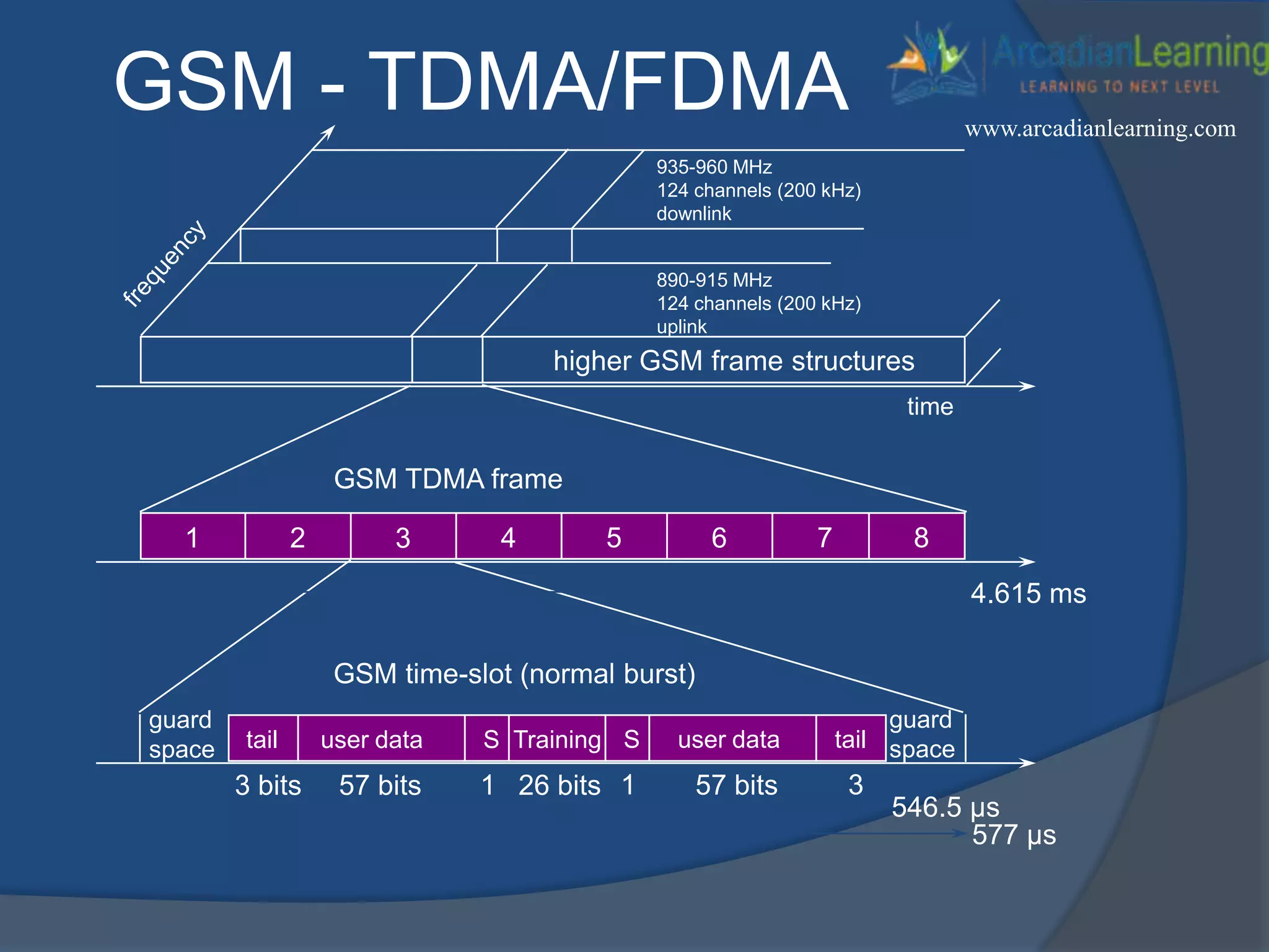
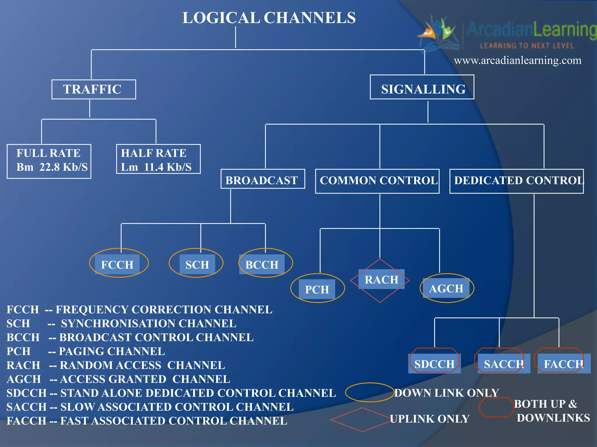
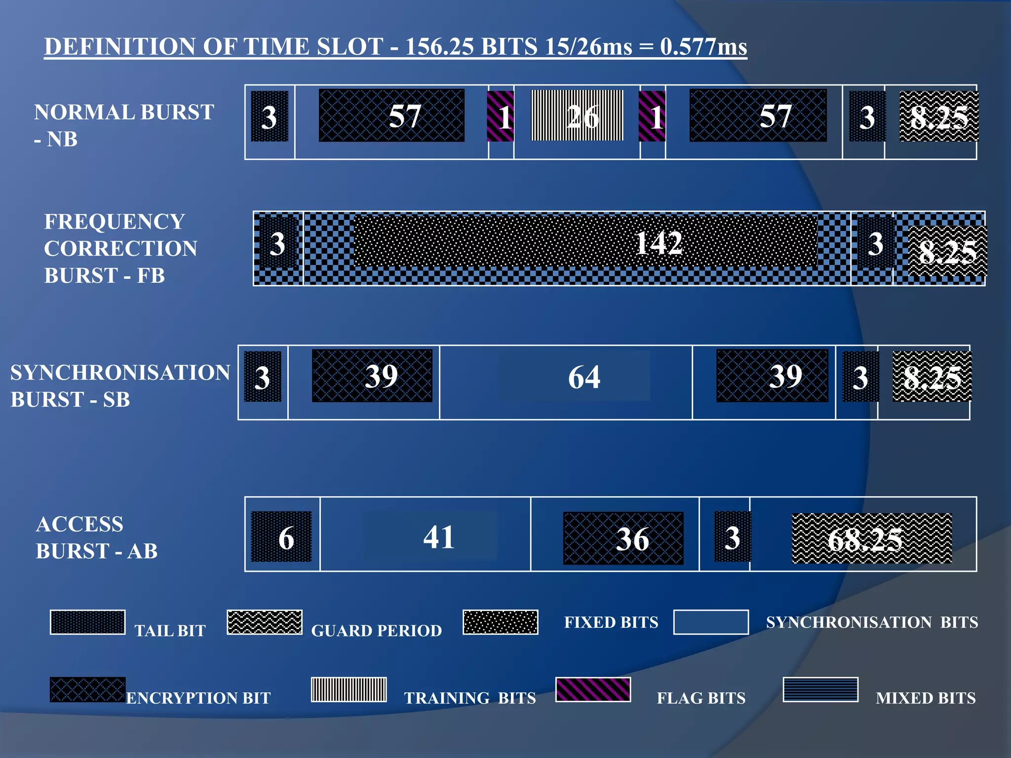

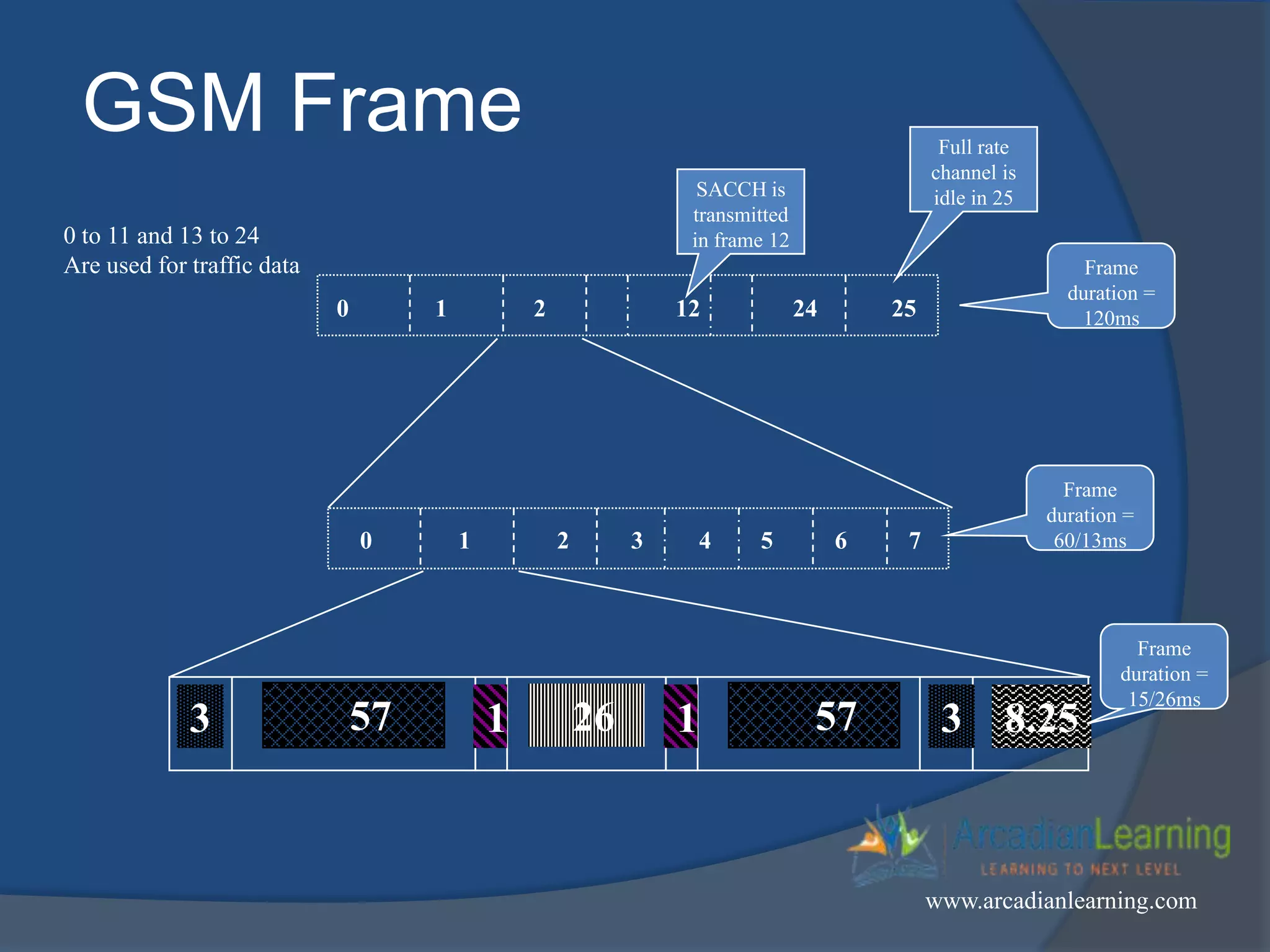
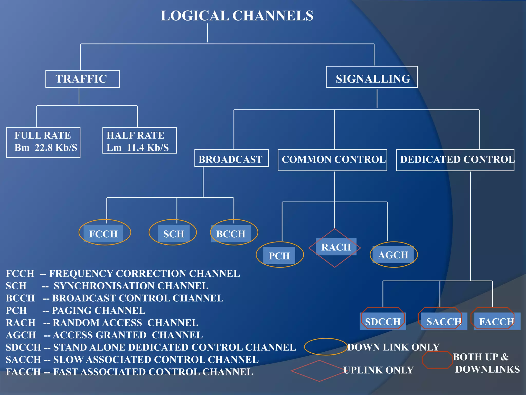
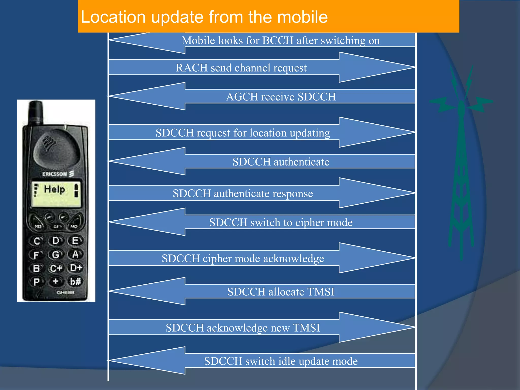
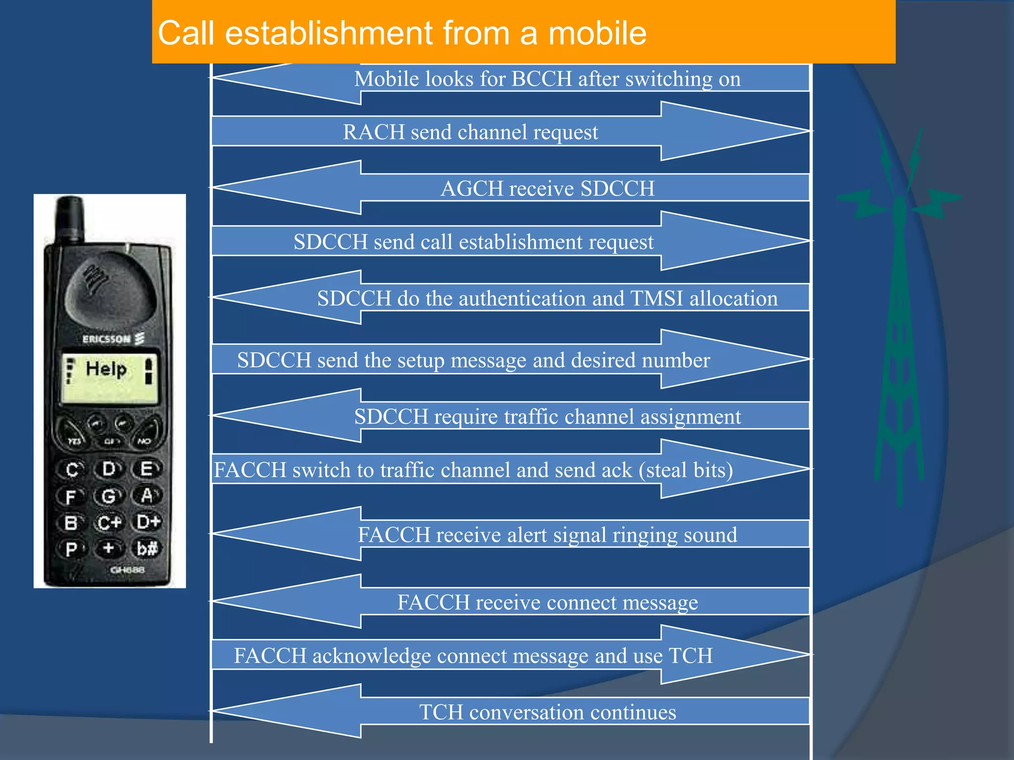
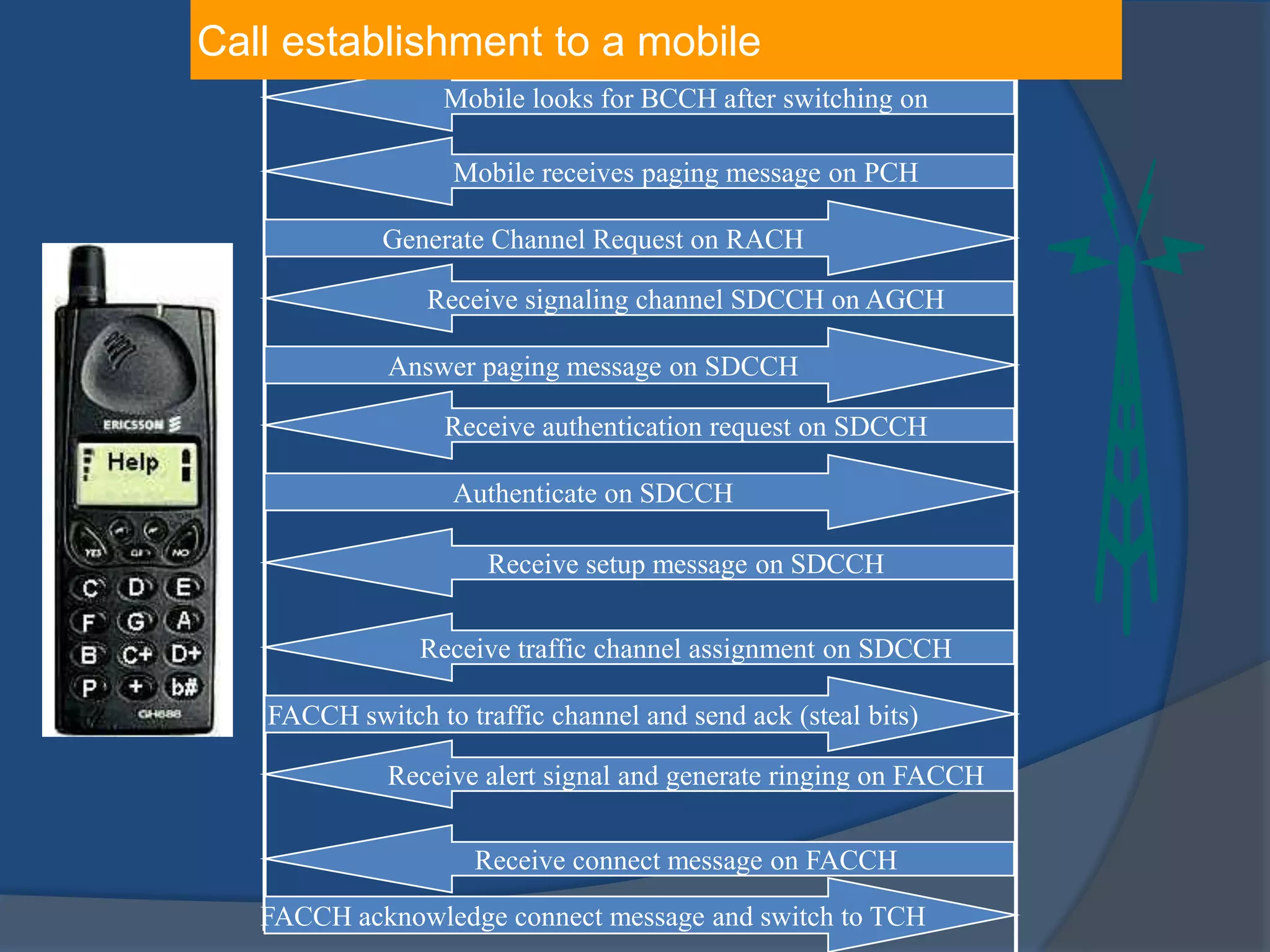
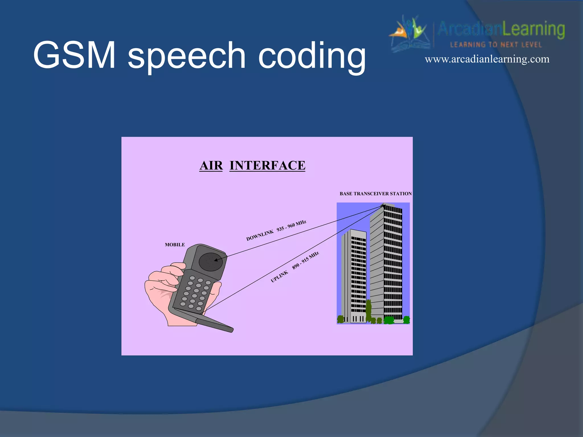
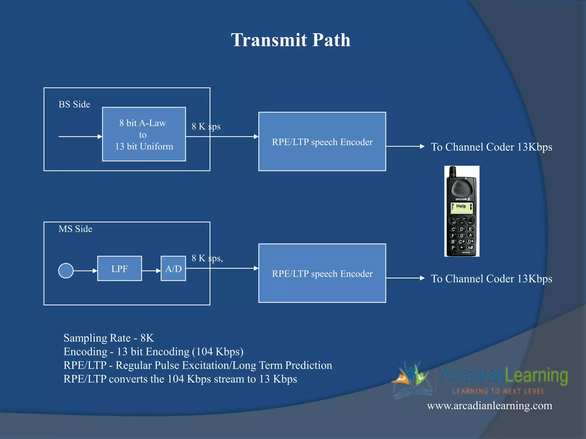
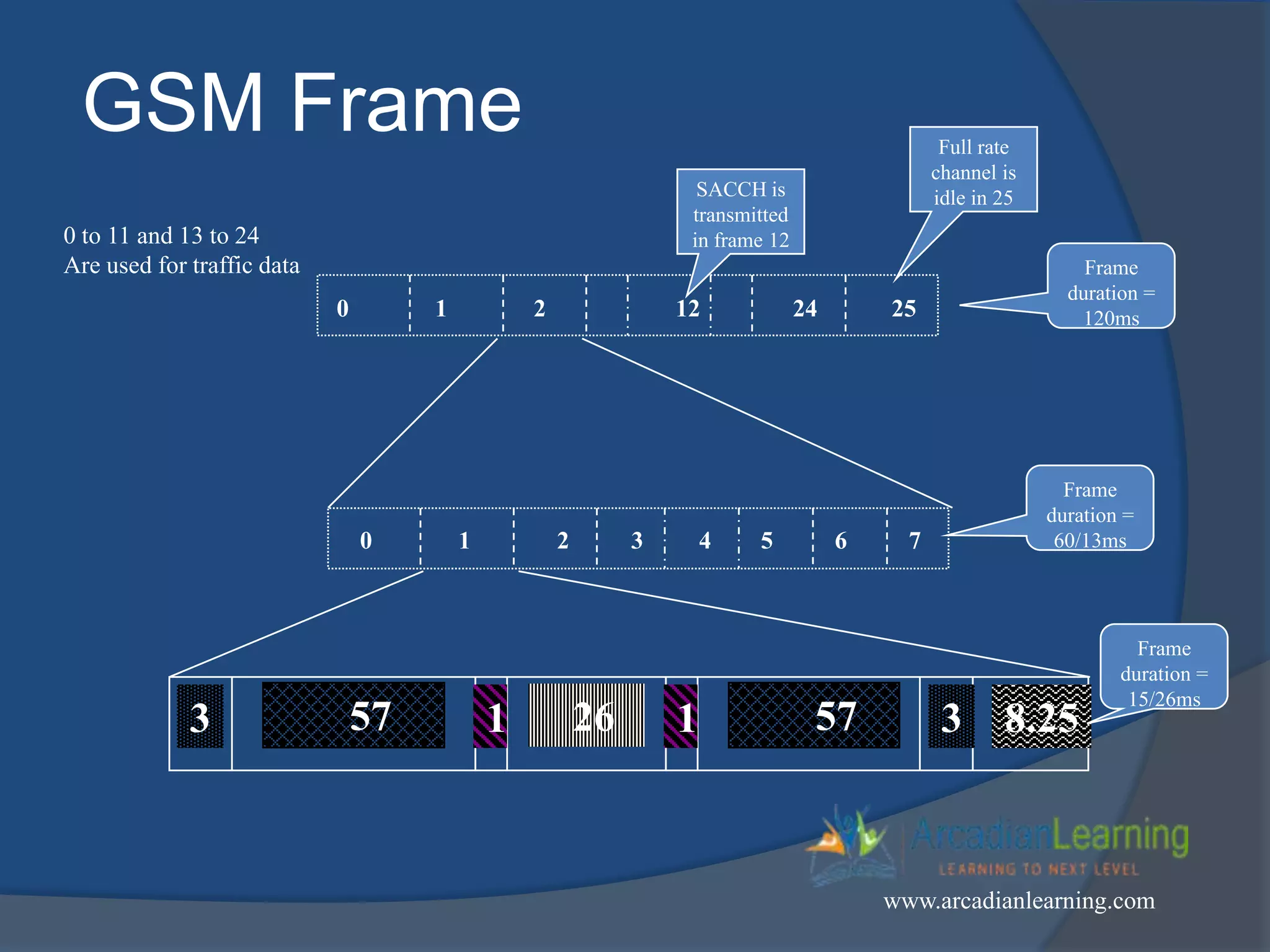
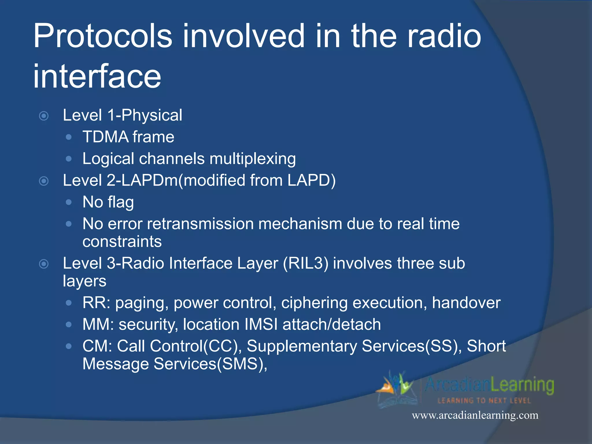


GSM combines frequency division multiple access (FDMA) and time division multiple access (TDMA) to allow multiple stations to access the same radio channel. The bandwidth is divided into 124 channels of 200 kHz each that are shared between up to eight mobile stations by assigning transmission slots. TDMA frames are 4.615 ms long and each frame is divided into 8 time slots of 577 μs. Uplink and downlink frames are offset by three time slots to avoid collisions. Logical channels include traffic channels, broadcast channels, common control channels, and dedicated control channels for functions like paging, synchronization, authentication and call setup. GSM uses pulse code modulation and RPE-LPC speech coding at 13 kbps to compress