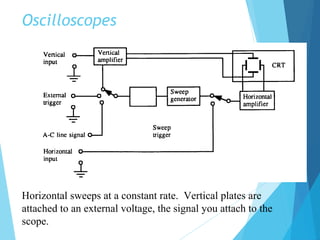
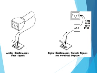
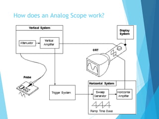
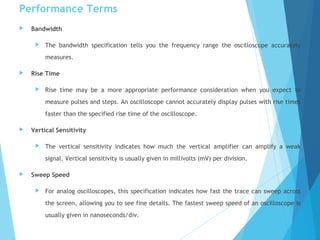
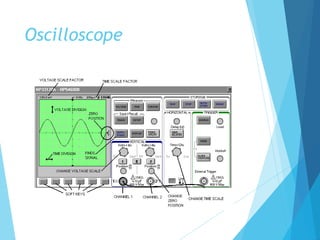
SlideShare a Scribd company logo
Oscilloscope Tutorial
 The oscilloscope is basically a graph-displaying device
 It draws a graph of an electrical signal.
 In most applications the graph shows how signals change
over time:
 the vertical (Y) axis represents voltage
 the horizontal (X) axis represents time. 65
 56
 45
 453
 6
 56
 35
Oscilloscopes
Horizontal sweeps at a constant rate. Vertical plates are
attached to an external voltage, the signal you attach to the
scope.
Scope (Con’t)
 This simple graph can tell you many things
about a signal:
 You can determine the time and voltage values of
a signal.
 You can calculate the frequency of an oscillating
signal.
 You can see the "moving parts" of a circuit
represented by the signal.
 You can tell if a malfunctioning component is
distorting the signal.
 You can find out how much of a signal is direct
current (DC) or alternating current (AC).
 You can tell how much of the signal is noise and
whether the noise is changing with time.
How does an Analog Scope work?
How does a Digital Scope work?
Triggering Stabilizes a Repeating
Waveform
Waveform shapes tell you a great deal about a signal
If a signal repeats, it has a frequency. The frequency is
measured in Hertz (Hz) and equals the number of times the
signal repeats itself in one second
Voltage, Current, & Phase
Performance Terms
 Bandwidth
 The bandwidth specification tells you the frequency range the oscilloscope accurately
measures.
 Rise Time
 Rise time may be a more appropriate performance consideration when you expect to
measure pulses and steps. An oscilloscope cannot accurately display pulses with rise times
faster than the specified rise time of the oscilloscope.
 Vertical Sensitivity
 The vertical sensitivity indicates how much the vertical amplifier can amplify a weak
signal. Vertical sensitivity is usually given in millivolts (mV) per division.
 Sweep Speed
 For analog oscilloscopes, this specification indicates how fast the trace can sweep across
the screen, allowing you to see fine details. The fastest sweep speed of an oscilloscope is
usually given in nanoseconds/div.
 Gain Accuracy
 The gain accuracy indicates how accurately the vertical system attenuates or amplifies a
signal.
 Time Base or Horizontal Accuracy
 The time base or horizontal accuracy indicates how accurately the horizontal system
displays the timing of a signal.
Sample Rate
 On digital oscilloscopes, the sampling rate indicates how many samples per second the
ADC can acquire. Maximum sample rates are usually given in megasamples per second
(MS/s). The faster the oscilloscope can sample, the more accurately it can represent fine
details in a fast signal..
 ADC Resolution (Or Vertical Resolution)
 The resolution, in bits, of the ADC indicates how precisely it can turn input voltages into
digital values.
 Record Length
 The record length of a digital oscilloscope indicates how many waveform points the
oscilloscope is able to acquire for one waveform record.
Grounding
 Proper grounding is an important step when setting up to take measurements.
 Properly grounding the oscilloscope protects you from a hazardous shock and protects
your circuits from damage.
 Grounding the oscilloscope is necessary for safety. If a high voltage contacts the case of
an ungrounded oscilloscope, any part of the case, including knobs that appear
insulated, it can give you a shock. However, with a properly grounded oscilloscope, the
current travels through the grounding path to earth ground rather than through you to
earth ground.
 To ground the oscilloscope means to connect it to an electrically neutral reference
point (such as earth ground). Ground your oscilloscope by plugging its three-pronged
power cord into an outlet grounded to earth ground.
 Grounding is also necessary for taking accurate measurements with your oscilloscope.
The oscilloscope needs to share the same ground as any circuits you are testing.
 Some oscilloscopes do not require the separate connection to earth ground. These
oscilloscopes have insulated cases and controls, which keeps any possible shock hazard
away from the user.
Scope Probes
Most passive probes have some degree of attenuation factor, such as
10X, 100X, and so on. By convention, attenuation factors, such as for the
10X attenuator probe, have the X after the factor.
In contrast, magnification factors like X10 have the X first
Vertical Controls
 Position and Volts per Division
 The vertical position control lets you move the
waveform up or down to exactly where you want it
on the screen.
 The volts per division (usually written volts/div)
setting varies the size of the waveform on the
screen. A good general purpose oscilloscope can
accurately display signal levels from about 4
millivolts to 40 volts.
 Often the volts/div scale has either a variable gain
or a fine gain control for scaling a displayed signal to
a certain number of divisions.
Input Coupling
 Coupling means the method used to connect an electrical signal from one
circuit to another.
Horizontal Controls
 Position and Seconds per Division
 The horizontal position control moves the waveform from left
and right to exactly where you want it on the screen.
 The seconds per division (usually written as sec/div) setting
lets you select the rate at which the waveform is drawn
across the screen (also known as the time base setting or
sweep speed). This setting is a scale factor. For example, if
the setting is 1 ms, each horizontal division represents 1 ms
and the total screen width represents 10 ms (ten divisions).
Changing the sec/div setting lets you look at longer or shorter
time intervals of the input signal.
Trigger Position
 The trigger position control may be located in the horizontal control section of
your oscilloscope. It actually represents "the horizontal position of the trigger in
the waveform record." Horizontal trigger position control is only available on
digital oscilloscopes.
 Varying the horizontal trigger position allows you to capture what a signal did
before a trigger event (called pretrigger viewing).
 Digital oscilloscopes can provide pretrigger viewing because they constantly
process the input signal whether a trigger has been received or not. A steady
stream of data flows through the oscilloscope; the trigger merely tells the
oscilloscope to save the present data in memory. I
 n contrast, analog oscilloscopes only display the signal after receiving the
trigger.
Trigger Controls (con’t)
Pulse and Rise Time Measurements
Multimeter tutorial
 A meter is a measuring instrument. An ammeter
measures current, a voltmeter measures the potential
difference (voltage) between two points, and an
ohmmeter measures resistance.
 A multimeter combines these functions, and possibly
some additional ones as well, into a single instrument.
To measure current, the circuit must be broken to allow
the
ammeter to be connected in series
Ammeters must have a LOW resistance
To measure potential difference (voltage), the circuit is not
changed: the voltmeter is connected in parallel
Voltmeters must have a HIGH resistance
To measure resistance, the component must be removed
from the circuit altogether
Ohmmeters work by passing a current through the
component being tested
Digital Multimeters
Digital meters give an output in numbers, usually on a liquid
crystal display.
Most modern multimeters are digital and traditional
analogue types are destined to become obsolete.
Digital multimeters come in a wide range of sizes and
capability. Everything from simple 3 ½ digit auto ranging
pocket meters to larger 8 ½ digit bench model with
operator or computer (IEEE488 compatible) settable range
selection
Function Generator
 An electronic instrument that generates various
waveforms such as
 Sine wave
 Square wave
 Pulse trains
 Sawtooth
 The amplitude, DC offset, frequency are adjustable.
Function Generators (con’t)
 Like multimeters there is a wide variety of device
offering various
 Amplitude characteristics
 Bandwidth
 Adjustments of rise and fall times
 Modulation capability (AM, FM, Pulse, etc.)
Power Supply
 This is the device that transfers electric power from a source to a load using
electronic circuits.
 Typical application of power supplies is to convert utility's AC input power to a
regulated voltage(s) required for electronic equipment.
 Depending on the mode of operation of power semiconductors PS can be linear or
switching.
 In a switched-mode power supply, or SMPS power handling electronic
components are continuously switching on and off with high frequency in order to
provide the transfer of electric energy. By varying duty cycle, frequency or a
phase of these transitions an output parameter (such as output voltage) is
controlled. Typical frequency range of SMPS is from 20 kHz to several MHz.
Power Supply (con’t)
 Power supplies like many of the other electronic instruments, come in
many varieties with a wide range of capabilities:
 Parameters that are Power Supply specific include:
 Voltage levels
 Current
 Regulation
 Protection
 Output impedance
 Noise (ripple)
 It’s the designer (or researcher) responsibility to identify the
characteristics required.
Oscilloscope
Oscilloscope(continue)
DEMO…….Lab3a
Oscilloscope tutorial

More Related Content

What's hot

adc dac converter
adc dac converteradc dac converter
adc dac converter
Gaurav Rai
 
Digital voltmeter (DVM) and its Classification
Digital voltmeter (DVM) and its ClassificationDigital voltmeter (DVM) and its Classification
Digital voltmeter (DVM) and its Classification
ST. MARTIN'S ENGINEERING COLLEGE
 
Unit 2
Unit 2Unit 2
Unit 2
tamilnesaner
 
Signal generators
Signal generatorsSignal generators
Signal generators
chethank27
 
Oscilloscope
OscilloscopeOscilloscope
Oscilloscope
prasadpawaskar
 
Operational amplifier
Operational amplifierOperational amplifier
Operational amplifier
Unsa Shakir
 
Pmmc instrument
Pmmc instrumentPmmc instrument
Pmmc instrument
GITAM UNIVERSITY
 
Function generator
Function generatorFunction generator
Function generator
Poojith Chowdhary
 
EC6202 ELECTRONIC DEVICES AND CIRCUITS Unit 2
EC6202 ELECTRONIC DEVICES AND CIRCUITS Unit 2EC6202 ELECTRONIC DEVICES AND CIRCUITS Unit 2
EC6202 ELECTRONIC DEVICES AND CIRCUITS Unit 2
RMK ENGINEERING COLLEGE, CHENNAI
 
OP AMP Applications
OP AMP ApplicationsOP AMP Applications
OP AMP Applications
aroosa khan
 
Q meter ppt
Q meter pptQ meter ppt
Q meter ppt
Pushkar Singh
 
Op amp(operational amplifier)
Op amp(operational amplifier)Op amp(operational amplifier)
Op amp(operational amplifier)
Kausik das
 
Moving iron (MI) instruments
Moving iron (MI) instrumentsMoving iron (MI) instruments
Moving iron (MI) instruments
Chandan Singh
 
Wave analyzers done by Priyanga KR
Wave analyzers done by Priyanga KRWave analyzers done by Priyanga KR
Wave analyzers done by Priyanga KR
PriyangaKR1
 
integrator and differentiator op-amp
integrator and differentiator op-ampintegrator and differentiator op-amp
integrator and differentiator op-amp
danish iqbal
 
Buck boost converter
Buck boost converterBuck boost converter
Buck boost converter
NazmushSakib7
 
Choppers
ChoppersChoppers
Oscilloscopes
OscilloscopesOscilloscopes
Oscilloscopes
napisham
 

What's hot (20)

Transducers ppt
Transducers pptTransducers ppt
Transducers ppt
 
adc dac converter
adc dac converteradc dac converter
adc dac converter
 
Digital voltmeter (DVM) and its Classification
Digital voltmeter (DVM) and its ClassificationDigital voltmeter (DVM) and its Classification
Digital voltmeter (DVM) and its Classification
 
Unit 2
Unit 2Unit 2
Unit 2
 
Signal generators
Signal generatorsSignal generators
Signal generators
 
Oscilloscope
OscilloscopeOscilloscope
Oscilloscope
 
Operational amplifier
Operational amplifierOperational amplifier
Operational amplifier
 
Pmmc instrument
Pmmc instrumentPmmc instrument
Pmmc instrument
 
Function generator
Function generatorFunction generator
Function generator
 
EC6202 ELECTRONIC DEVICES AND CIRCUITS Unit 2
EC6202 ELECTRONIC DEVICES AND CIRCUITS Unit 2EC6202 ELECTRONIC DEVICES AND CIRCUITS Unit 2
EC6202 ELECTRONIC DEVICES AND CIRCUITS Unit 2
 
OP AMP Applications
OP AMP ApplicationsOP AMP Applications
OP AMP Applications
 
Transducers
TransducersTransducers
Transducers
 
Q meter ppt
Q meter pptQ meter ppt
Q meter ppt
 
Op amp(operational amplifier)
Op amp(operational amplifier)Op amp(operational amplifier)
Op amp(operational amplifier)
 
Moving iron (MI) instruments
Moving iron (MI) instrumentsMoving iron (MI) instruments
Moving iron (MI) instruments
 
Wave analyzers done by Priyanga KR
Wave analyzers done by Priyanga KRWave analyzers done by Priyanga KR
Wave analyzers done by Priyanga KR
 
integrator and differentiator op-amp
integrator and differentiator op-ampintegrator and differentiator op-amp
integrator and differentiator op-amp
 
Buck boost converter
Buck boost converterBuck boost converter
Buck boost converter
 
Choppers
ChoppersChoppers
Choppers
 
Oscilloscopes
OscilloscopesOscilloscopes
Oscilloscopes
 

Similar to Oscilloscope tutorial

Free Ebooks Download
Free Ebooks DownloadFree Ebooks Download
Free Ebooks Download
Edhole.com
 
Fluke making sense-of-electrical-signals
Fluke making sense-of-electrical-signalsFluke making sense-of-electrical-signals
Fluke making sense-of-electrical-signals
hcsurfa
 
CRO
CROCRO
CRO
vmr1124
 
157929707-Presentation-on-Cro.pptx
157929707-Presentation-on-Cro.pptx157929707-Presentation-on-Cro.pptx
157929707-Presentation-on-Cro.pptx
pranjalmishra68
 
digital-oscilloscope 8051 Microcontroller.docx
digital-oscilloscope 8051 Microcontroller.docxdigital-oscilloscope 8051 Microcontroller.docx
digital-oscilloscope 8051 Microcontroller.docx
SajidHossainKhan1
 
cathode ray oscilloscope &function generator
cathode ray oscilloscope &function generatorcathode ray oscilloscope &function generator
cathode ray oscilloscope &function generatormegha agrawal
 
Cro cathode ray oscilloscope working and applications
Cro cathode ray oscilloscope working and applicationsCro cathode ray oscilloscope working and applications
Cro cathode ray oscilloscope working and applications
Edgefxkits & Solutions
 
Cathode ray oscilloscope
Cathode ray oscilloscopeCathode ray oscilloscope
Cathode ray oscilloscope
esmaeel21
 
CRO and functional generator physics
CRO and functional generator physicsCRO and functional generator physics
CRO and functional generator physics
Abdul Wahab Raza
 
Lab LCA 1 7
Lab LCA 1 7Lab LCA 1 7
Lab LCA 1 7
NUST Stuff
 
Cathode Ray Oscilloscope CRO & Digital Oscilloscope 'S WORKING
Cathode Ray Oscilloscope CRO & Digital Oscilloscope 'S WORKINGCathode Ray Oscilloscope CRO & Digital Oscilloscope 'S WORKING
Cathode Ray Oscilloscope CRO & Digital Oscilloscope 'S WORKING
Abdul Qayoom Mangrio
 
data-acquisition-system-ppt
data-acquisition-system-pptdata-acquisition-system-ppt
data-acquisition-system-ppt
Ravi Anand
 
Ie practical file
Ie practical fileIe practical file
Ie practical file
KANAIYABHATT
 
unit 4.pdf
unit 4.pdfunit 4.pdf
unit 4.pdf
ArcadePrinters
 
Cathode Ray Oscilloscope
Cathode Ray OscilloscopeCathode Ray Oscilloscope
Cathode Ray Oscilloscope
rajainayat
 
Unit1 measurement and tech(1b)
Unit1 measurement and tech(1b)Unit1 measurement and tech(1b)
Unit1 measurement and tech(1b)Hira Rizvi
 
1.Oscilloscope. 2.Block diagram of Oscilloscope. 3.Types of Oscilloscope. 4.A...
1.Oscilloscope. 2.Block diagram of Oscilloscope. 3.Types of Oscilloscope. 4.A...1.Oscilloscope. 2.Block diagram of Oscilloscope. 3.Types of Oscilloscope. 4.A...
1.Oscilloscope. 2.Block diagram of Oscilloscope. 3.Types of Oscilloscope. 4.A...
AL- AMIN
 
Oscilloscope
OscilloscopeOscilloscope
CHapter 4 -Signal Conditioning.pptxyyhhhj
CHapter 4 -Signal Conditioning.pptxyyhhhjCHapter 4 -Signal Conditioning.pptxyyhhhj
CHapter 4 -Signal Conditioning.pptxyyhhhj
teddiyfentaw
 

Similar to Oscilloscope tutorial (20)

Free Ebooks Download
Free Ebooks DownloadFree Ebooks Download
Free Ebooks Download
 
Fluke making sense-of-electrical-signals
Fluke making sense-of-electrical-signalsFluke making sense-of-electrical-signals
Fluke making sense-of-electrical-signals
 
CRO
CROCRO
CRO
 
157929707-Presentation-on-Cro.pptx
157929707-Presentation-on-Cro.pptx157929707-Presentation-on-Cro.pptx
157929707-Presentation-on-Cro.pptx
 
digital-oscilloscope 8051 Microcontroller.docx
digital-oscilloscope 8051 Microcontroller.docxdigital-oscilloscope 8051 Microcontroller.docx
digital-oscilloscope 8051 Microcontroller.docx
 
cathode ray oscilloscope &function generator
cathode ray oscilloscope &function generatorcathode ray oscilloscope &function generator
cathode ray oscilloscope &function generator
 
Cro cathode ray oscilloscope working and applications
Cro cathode ray oscilloscope working and applicationsCro cathode ray oscilloscope working and applications
Cro cathode ray oscilloscope working and applications
 
Cathode ray oscilloscope
Cathode ray oscilloscopeCathode ray oscilloscope
Cathode ray oscilloscope
 
CRO and functional generator physics
CRO and functional generator physicsCRO and functional generator physics
CRO and functional generator physics
 
Lab LCA 1 7
Lab LCA 1 7Lab LCA 1 7
Lab LCA 1 7
 
Cathode Ray Oscilloscope CRO & Digital Oscilloscope 'S WORKING
Cathode Ray Oscilloscope CRO & Digital Oscilloscope 'S WORKINGCathode Ray Oscilloscope CRO & Digital Oscilloscope 'S WORKING
Cathode Ray Oscilloscope CRO & Digital Oscilloscope 'S WORKING
 
data-acquisition-system-ppt
data-acquisition-system-pptdata-acquisition-system-ppt
data-acquisition-system-ppt
 
Ie practical file
Ie practical fileIe practical file
Ie practical file
 
unit 4.pdf
unit 4.pdfunit 4.pdf
unit 4.pdf
 
Cathode Ray Oscilloscope
Cathode Ray OscilloscopeCathode Ray Oscilloscope
Cathode Ray Oscilloscope
 
Unit1 measurement and tech(1b)
Unit1 measurement and tech(1b)Unit1 measurement and tech(1b)
Unit1 measurement and tech(1b)
 
Testing
TestingTesting
Testing
 
1.Oscilloscope. 2.Block diagram of Oscilloscope. 3.Types of Oscilloscope. 4.A...
1.Oscilloscope. 2.Block diagram of Oscilloscope. 3.Types of Oscilloscope. 4.A...1.Oscilloscope. 2.Block diagram of Oscilloscope. 3.Types of Oscilloscope. 4.A...
1.Oscilloscope. 2.Block diagram of Oscilloscope. 3.Types of Oscilloscope. 4.A...
 
Oscilloscope
OscilloscopeOscilloscope
Oscilloscope
 
CHapter 4 -Signal Conditioning.pptxyyhhhj
CHapter 4 -Signal Conditioning.pptxyyhhhjCHapter 4 -Signal Conditioning.pptxyyhhhj
CHapter 4 -Signal Conditioning.pptxyyhhhj
 

More from Saumya Ranjan Behura

Gsm
GsmGsm
Quadcopters
QuadcoptersQuadcopters
Nano technology
Nano technologyNano technology
Nano technology
Saumya Ranjan Behura
 
Miling machine
Miling machineMiling machine
Miling machine
Saumya Ranjan Behura
 
Manglev train
Manglev trainManglev train
Manglev train
Saumya Ranjan Behura
 
E nose
E noseE nose
Clockless chips
Clockless chipsClockless chips
Clockless chips
Saumya Ranjan Behura
 
Cell phone jammers
Cell phone jammersCell phone jammers
Cell phone jammers
Saumya Ranjan Behura
 
Blu ray disk
Blu ray diskBlu ray disk
Blu ray disk
Saumya Ranjan Behura
 
Bit torrent
Bit torrentBit torrent
Bio chemical senors
Bio chemical senorsBio chemical senors
Bio chemical senors
Saumya Ranjan Behura
 
Analog to digital converters, adc
Analog to digital converters, adcAnalog to digital converters, adc
Analog to digital converters, adc
Saumya Ranjan Behura
 
Seminar on nanorobotics
Seminar on nanoroboticsSeminar on nanorobotics
Seminar on nanorobotics
Saumya Ranjan Behura
 
Security system wireless technology
Security system wireless technologySecurity system wireless technology
Security system wireless technology
Saumya Ranjan Behura
 
Oscilloscopes basics
Oscilloscopes basicsOscilloscopes basics
Oscilloscopes basics
Saumya Ranjan Behura
 
Optical sensors and their applications
Optical sensors and their applicationsOptical sensors and their applications
Optical sensors and their applications
Saumya Ranjan Behura
 
Night vision
Night visionNight vision
Night vision
Saumya Ranjan Behura
 
Sensors and transducer
Sensors and transducerSensors and transducer
Sensors and transducer
Saumya Ranjan Behura
 
Sensors
SensorsSensors
Smart card
Smart cardSmart card

More from Saumya Ranjan Behura (20)

Gsm
GsmGsm
Gsm
 
Quadcopters
QuadcoptersQuadcopters
Quadcopters
 
Nano technology
Nano technologyNano technology
Nano technology
 
Miling machine
Miling machineMiling machine
Miling machine
 
Manglev train
Manglev trainManglev train
Manglev train
 
E nose
E noseE nose
E nose
 
Clockless chips
Clockless chipsClockless chips
Clockless chips
 
Cell phone jammers
Cell phone jammersCell phone jammers
Cell phone jammers
 
Blu ray disk
Blu ray diskBlu ray disk
Blu ray disk
 
Bit torrent
Bit torrentBit torrent
Bit torrent
 
Bio chemical senors
Bio chemical senorsBio chemical senors
Bio chemical senors
 
Analog to digital converters, adc
Analog to digital converters, adcAnalog to digital converters, adc
Analog to digital converters, adc
 
Seminar on nanorobotics
Seminar on nanoroboticsSeminar on nanorobotics
Seminar on nanorobotics
 
Security system wireless technology
Security system wireless technologySecurity system wireless technology
Security system wireless technology
 
Oscilloscopes basics
Oscilloscopes basicsOscilloscopes basics
Oscilloscopes basics
 
Optical sensors and their applications
Optical sensors and their applicationsOptical sensors and their applications
Optical sensors and their applications
 
Night vision
Night visionNight vision
Night vision
 
Sensors and transducer
Sensors and transducerSensors and transducer
Sensors and transducer
 
Sensors
SensorsSensors
Sensors
 
Smart card
Smart cardSmart card
Smart card
 

Recently uploaded

State of ICS and IoT Cyber Threat Landscape Report 2024 preview
State of ICS and IoT Cyber Threat Landscape Report 2024 previewState of ICS and IoT Cyber Threat Landscape Report 2024 preview
State of ICS and IoT Cyber Threat Landscape Report 2024 preview
Prayukth K V
 
Builder.ai Founder Sachin Dev Duggal's Strategic Approach to Create an Innova...
Builder.ai Founder Sachin Dev Duggal's Strategic Approach to Create an Innova...Builder.ai Founder Sachin Dev Duggal's Strategic Approach to Create an Innova...
Builder.ai Founder Sachin Dev Duggal's Strategic Approach to Create an Innova...
Ramesh Iyer
 
LF Energy Webinar: Electrical Grid Modelling and Simulation Through PowSyBl -...
LF Energy Webinar: Electrical Grid Modelling and Simulation Through PowSyBl -...LF Energy Webinar: Electrical Grid Modelling and Simulation Through PowSyBl -...
LF Energy Webinar: Electrical Grid Modelling and Simulation Through PowSyBl -...
DanBrown980551
 
Bits & Pixels using AI for Good.........
Bits & Pixels using AI for Good.........Bits & Pixels using AI for Good.........
Bits & Pixels using AI for Good.........
Alison B. Lowndes
 
The Art of the Pitch: WordPress Relationships and Sales
The Art of the Pitch: WordPress Relationships and SalesThe Art of the Pitch: WordPress Relationships and Sales
The Art of the Pitch: WordPress Relationships and Sales
Laura Byrne
 
Mission to Decommission: Importance of Decommissioning Products to Increase E...
Mission to Decommission: Importance of Decommissioning Products to Increase E...Mission to Decommission: Importance of Decommissioning Products to Increase E...
Mission to Decommission: Importance of Decommissioning Products to Increase E...
Product School
 
Accelerate your Kubernetes clusters with Varnish Caching
Accelerate your Kubernetes clusters with Varnish CachingAccelerate your Kubernetes clusters with Varnish Caching
Accelerate your Kubernetes clusters with Varnish Caching
Thijs Feryn
 
Software Delivery At the Speed of AI: Inflectra Invests In AI-Powered Quality
Software Delivery At the Speed of AI: Inflectra Invests In AI-Powered QualitySoftware Delivery At the Speed of AI: Inflectra Invests In AI-Powered Quality
Software Delivery At the Speed of AI: Inflectra Invests In AI-Powered Quality
Inflectra
 
Epistemic Interaction - tuning interfaces to provide information for AI support
Epistemic Interaction - tuning interfaces to provide information for AI supportEpistemic Interaction - tuning interfaces to provide information for AI support
Epistemic Interaction - tuning interfaces to provide information for AI support
Alan Dix
 
GraphRAG is All You need? LLM & Knowledge Graph
GraphRAG is All You need? LLM & Knowledge GraphGraphRAG is All You need? LLM & Knowledge Graph
GraphRAG is All You need? LLM & Knowledge Graph
Guy Korland
 
The Future of Platform Engineering
The Future of Platform EngineeringThe Future of Platform Engineering
The Future of Platform Engineering
Jemma Hussein Allen
 
Search and Society: Reimagining Information Access for Radical Futures
Search and Society: Reimagining Information Access for Radical FuturesSearch and Society: Reimagining Information Access for Radical Futures
Search and Society: Reimagining Information Access for Radical Futures
Bhaskar Mitra
 
PHP Frameworks: I want to break free (IPC Berlin 2024)
PHP Frameworks: I want to break free (IPC Berlin 2024)PHP Frameworks: I want to break free (IPC Berlin 2024)
PHP Frameworks: I want to break free (IPC Berlin 2024)
Ralf Eggert
 
DevOps and Testing slides at DASA Connect
DevOps and Testing slides at DASA ConnectDevOps and Testing slides at DASA Connect
DevOps and Testing slides at DASA Connect
Kari Kakkonen
 
UiPath Test Automation using UiPath Test Suite series, part 3
UiPath Test Automation using UiPath Test Suite series, part 3UiPath Test Automation using UiPath Test Suite series, part 3
UiPath Test Automation using UiPath Test Suite series, part 3
DianaGray10
 
"Impact of front-end architecture on development cost", Viktor Turskyi
"Impact of front-end architecture on development cost", Viktor Turskyi"Impact of front-end architecture on development cost", Viktor Turskyi
"Impact of front-end architecture on development cost", Viktor Turskyi
Fwdays
 
Connector Corner: Automate dynamic content and events by pushing a button
Connector Corner: Automate dynamic content and events by pushing a buttonConnector Corner: Automate dynamic content and events by pushing a button
Connector Corner: Automate dynamic content and events by pushing a button
DianaGray10
 
Leading Change strategies and insights for effective change management pdf 1.pdf
Leading Change strategies and insights for effective change management pdf 1.pdfLeading Change strategies and insights for effective change management pdf 1.pdf
Leading Change strategies and insights for effective change management pdf 1.pdf
OnBoard
 
Essentials of Automations: Optimizing FME Workflows with Parameters
Essentials of Automations: Optimizing FME Workflows with ParametersEssentials of Automations: Optimizing FME Workflows with Parameters
Essentials of Automations: Optimizing FME Workflows with Parameters
Safe Software
 
Key Trends Shaping the Future of Infrastructure.pdf
Key Trends Shaping the Future of Infrastructure.pdfKey Trends Shaping the Future of Infrastructure.pdf
Key Trends Shaping the Future of Infrastructure.pdf
Cheryl Hung
 

Recently uploaded (20)

State of ICS and IoT Cyber Threat Landscape Report 2024 preview
State of ICS and IoT Cyber Threat Landscape Report 2024 previewState of ICS and IoT Cyber Threat Landscape Report 2024 preview
State of ICS and IoT Cyber Threat Landscape Report 2024 preview
 
Builder.ai Founder Sachin Dev Duggal's Strategic Approach to Create an Innova...
Builder.ai Founder Sachin Dev Duggal's Strategic Approach to Create an Innova...Builder.ai Founder Sachin Dev Duggal's Strategic Approach to Create an Innova...
Builder.ai Founder Sachin Dev Duggal's Strategic Approach to Create an Innova...
 
LF Energy Webinar: Electrical Grid Modelling and Simulation Through PowSyBl -...
LF Energy Webinar: Electrical Grid Modelling and Simulation Through PowSyBl -...LF Energy Webinar: Electrical Grid Modelling and Simulation Through PowSyBl -...
LF Energy Webinar: Electrical Grid Modelling and Simulation Through PowSyBl -...
 
Bits & Pixels using AI for Good.........
Bits & Pixels using AI for Good.........Bits & Pixels using AI for Good.........
Bits & Pixels using AI for Good.........
 
The Art of the Pitch: WordPress Relationships and Sales
The Art of the Pitch: WordPress Relationships and SalesThe Art of the Pitch: WordPress Relationships and Sales
The Art of the Pitch: WordPress Relationships and Sales
 
Mission to Decommission: Importance of Decommissioning Products to Increase E...
Mission to Decommission: Importance of Decommissioning Products to Increase E...Mission to Decommission: Importance of Decommissioning Products to Increase E...
Mission to Decommission: Importance of Decommissioning Products to Increase E...
 
Accelerate your Kubernetes clusters with Varnish Caching
Accelerate your Kubernetes clusters with Varnish CachingAccelerate your Kubernetes clusters with Varnish Caching
Accelerate your Kubernetes clusters with Varnish Caching
 
Software Delivery At the Speed of AI: Inflectra Invests In AI-Powered Quality
Software Delivery At the Speed of AI: Inflectra Invests In AI-Powered QualitySoftware Delivery At the Speed of AI: Inflectra Invests In AI-Powered Quality
Software Delivery At the Speed of AI: Inflectra Invests In AI-Powered Quality
 
Epistemic Interaction - tuning interfaces to provide information for AI support
Epistemic Interaction - tuning interfaces to provide information for AI supportEpistemic Interaction - tuning interfaces to provide information for AI support
Epistemic Interaction - tuning interfaces to provide information for AI support
 
GraphRAG is All You need? LLM & Knowledge Graph
GraphRAG is All You need? LLM & Knowledge GraphGraphRAG is All You need? LLM & Knowledge Graph
GraphRAG is All You need? LLM & Knowledge Graph
 
The Future of Platform Engineering
The Future of Platform EngineeringThe Future of Platform Engineering
The Future of Platform Engineering
 
Search and Society: Reimagining Information Access for Radical Futures
Search and Society: Reimagining Information Access for Radical FuturesSearch and Society: Reimagining Information Access for Radical Futures
Search and Society: Reimagining Information Access for Radical Futures
 
PHP Frameworks: I want to break free (IPC Berlin 2024)
PHP Frameworks: I want to break free (IPC Berlin 2024)PHP Frameworks: I want to break free (IPC Berlin 2024)
PHP Frameworks: I want to break free (IPC Berlin 2024)
 
DevOps and Testing slides at DASA Connect
DevOps and Testing slides at DASA ConnectDevOps and Testing slides at DASA Connect
DevOps and Testing slides at DASA Connect
 
UiPath Test Automation using UiPath Test Suite series, part 3
UiPath Test Automation using UiPath Test Suite series, part 3UiPath Test Automation using UiPath Test Suite series, part 3
UiPath Test Automation using UiPath Test Suite series, part 3
 
"Impact of front-end architecture on development cost", Viktor Turskyi
"Impact of front-end architecture on development cost", Viktor Turskyi"Impact of front-end architecture on development cost", Viktor Turskyi
"Impact of front-end architecture on development cost", Viktor Turskyi
 
Connector Corner: Automate dynamic content and events by pushing a button
Connector Corner: Automate dynamic content and events by pushing a buttonConnector Corner: Automate dynamic content and events by pushing a button
Connector Corner: Automate dynamic content and events by pushing a button
 
Leading Change strategies and insights for effective change management pdf 1.pdf
Leading Change strategies and insights for effective change management pdf 1.pdfLeading Change strategies and insights for effective change management pdf 1.pdf
Leading Change strategies and insights for effective change management pdf 1.pdf
 
Essentials of Automations: Optimizing FME Workflows with Parameters
Essentials of Automations: Optimizing FME Workflows with ParametersEssentials of Automations: Optimizing FME Workflows with Parameters
Essentials of Automations: Optimizing FME Workflows with Parameters
 
Key Trends Shaping the Future of Infrastructure.pdf
Key Trends Shaping the Future of Infrastructure.pdfKey Trends Shaping the Future of Infrastructure.pdf
Key Trends Shaping the Future of Infrastructure.pdf
 

Oscilloscope tutorial

  • 1. Oscilloscope Tutorial  The oscilloscope is basically a graph-displaying device  It draws a graph of an electrical signal.  In most applications the graph shows how signals change over time:  the vertical (Y) axis represents voltage  the horizontal (X) axis represents time. 65  56  45  453  6  56  35
  • 2. Oscilloscopes Horizontal sweeps at a constant rate. Vertical plates are attached to an external voltage, the signal you attach to the scope.
  • 3.
  • 4. Scope (Con’t)  This simple graph can tell you many things about a signal:  You can determine the time and voltage values of a signal.  You can calculate the frequency of an oscillating signal.  You can see the "moving parts" of a circuit represented by the signal.  You can tell if a malfunctioning component is distorting the signal.  You can find out how much of a signal is direct current (DC) or alternating current (AC).  You can tell how much of the signal is noise and whether the noise is changing with time.
  • 5.
  • 6. How does an Analog Scope work?
  • 7. How does a Digital Scope work?
  • 8. Triggering Stabilizes a Repeating Waveform
  • 9. Waveform shapes tell you a great deal about a signal
  • 10. If a signal repeats, it has a frequency. The frequency is measured in Hertz (Hz) and equals the number of times the signal repeats itself in one second
  • 12. Performance Terms  Bandwidth  The bandwidth specification tells you the frequency range the oscilloscope accurately measures.  Rise Time  Rise time may be a more appropriate performance consideration when you expect to measure pulses and steps. An oscilloscope cannot accurately display pulses with rise times faster than the specified rise time of the oscilloscope.  Vertical Sensitivity  The vertical sensitivity indicates how much the vertical amplifier can amplify a weak signal. Vertical sensitivity is usually given in millivolts (mV) per division.  Sweep Speed  For analog oscilloscopes, this specification indicates how fast the trace can sweep across the screen, allowing you to see fine details. The fastest sweep speed of an oscilloscope is usually given in nanoseconds/div.
  • 13.  Gain Accuracy  The gain accuracy indicates how accurately the vertical system attenuates or amplifies a signal.  Time Base or Horizontal Accuracy  The time base or horizontal accuracy indicates how accurately the horizontal system displays the timing of a signal. Sample Rate  On digital oscilloscopes, the sampling rate indicates how many samples per second the ADC can acquire. Maximum sample rates are usually given in megasamples per second (MS/s). The faster the oscilloscope can sample, the more accurately it can represent fine details in a fast signal..  ADC Resolution (Or Vertical Resolution)  The resolution, in bits, of the ADC indicates how precisely it can turn input voltages into digital values.  Record Length  The record length of a digital oscilloscope indicates how many waveform points the oscilloscope is able to acquire for one waveform record.
  • 14. Grounding  Proper grounding is an important step when setting up to take measurements.  Properly grounding the oscilloscope protects you from a hazardous shock and protects your circuits from damage.  Grounding the oscilloscope is necessary for safety. If a high voltage contacts the case of an ungrounded oscilloscope, any part of the case, including knobs that appear insulated, it can give you a shock. However, with a properly grounded oscilloscope, the current travels through the grounding path to earth ground rather than through you to earth ground.  To ground the oscilloscope means to connect it to an electrically neutral reference point (such as earth ground). Ground your oscilloscope by plugging its three-pronged power cord into an outlet grounded to earth ground.  Grounding is also necessary for taking accurate measurements with your oscilloscope. The oscilloscope needs to share the same ground as any circuits you are testing.  Some oscilloscopes do not require the separate connection to earth ground. These oscilloscopes have insulated cases and controls, which keeps any possible shock hazard away from the user.
  • 15. Scope Probes Most passive probes have some degree of attenuation factor, such as 10X, 100X, and so on. By convention, attenuation factors, such as for the 10X attenuator probe, have the X after the factor. In contrast, magnification factors like X10 have the X first
  • 16. Vertical Controls  Position and Volts per Division  The vertical position control lets you move the waveform up or down to exactly where you want it on the screen.  The volts per division (usually written volts/div) setting varies the size of the waveform on the screen. A good general purpose oscilloscope can accurately display signal levels from about 4 millivolts to 40 volts.  Often the volts/div scale has either a variable gain or a fine gain control for scaling a displayed signal to a certain number of divisions.
  • 17. Input Coupling  Coupling means the method used to connect an electrical signal from one circuit to another.
  • 18. Horizontal Controls  Position and Seconds per Division  The horizontal position control moves the waveform from left and right to exactly where you want it on the screen.  The seconds per division (usually written as sec/div) setting lets you select the rate at which the waveform is drawn across the screen (also known as the time base setting or sweep speed). This setting is a scale factor. For example, if the setting is 1 ms, each horizontal division represents 1 ms and the total screen width represents 10 ms (ten divisions). Changing the sec/div setting lets you look at longer or shorter time intervals of the input signal.
  • 19. Trigger Position  The trigger position control may be located in the horizontal control section of your oscilloscope. It actually represents "the horizontal position of the trigger in the waveform record." Horizontal trigger position control is only available on digital oscilloscopes.  Varying the horizontal trigger position allows you to capture what a signal did before a trigger event (called pretrigger viewing).  Digital oscilloscopes can provide pretrigger viewing because they constantly process the input signal whether a trigger has been received or not. A steady stream of data flows through the oscilloscope; the trigger merely tells the oscilloscope to save the present data in memory. I  n contrast, analog oscilloscopes only display the signal after receiving the trigger.
  • 21. Pulse and Rise Time Measurements
  • 22. Multimeter tutorial  A meter is a measuring instrument. An ammeter measures current, a voltmeter measures the potential difference (voltage) between two points, and an ohmmeter measures resistance.  A multimeter combines these functions, and possibly some additional ones as well, into a single instrument.
  • 23. To measure current, the circuit must be broken to allow the ammeter to be connected in series Ammeters must have a LOW resistance
  • 24. To measure potential difference (voltage), the circuit is not changed: the voltmeter is connected in parallel Voltmeters must have a HIGH resistance
  • 25. To measure resistance, the component must be removed from the circuit altogether Ohmmeters work by passing a current through the component being tested
  • 26. Digital Multimeters Digital meters give an output in numbers, usually on a liquid crystal display. Most modern multimeters are digital and traditional analogue types are destined to become obsolete. Digital multimeters come in a wide range of sizes and capability. Everything from simple 3 ½ digit auto ranging pocket meters to larger 8 ½ digit bench model with operator or computer (IEEE488 compatible) settable range selection
  • 27. Function Generator  An electronic instrument that generates various waveforms such as  Sine wave  Square wave  Pulse trains  Sawtooth  The amplitude, DC offset, frequency are adjustable.
  • 28. Function Generators (con’t)  Like multimeters there is a wide variety of device offering various  Amplitude characteristics  Bandwidth  Adjustments of rise and fall times  Modulation capability (AM, FM, Pulse, etc.)
  • 29. Power Supply  This is the device that transfers electric power from a source to a load using electronic circuits.  Typical application of power supplies is to convert utility's AC input power to a regulated voltage(s) required for electronic equipment.  Depending on the mode of operation of power semiconductors PS can be linear or switching.  In a switched-mode power supply, or SMPS power handling electronic components are continuously switching on and off with high frequency in order to provide the transfer of electric energy. By varying duty cycle, frequency or a phase of these transitions an output parameter (such as output voltage) is controlled. Typical frequency range of SMPS is from 20 kHz to several MHz.
  • 30. Power Supply (con’t)  Power supplies like many of the other electronic instruments, come in many varieties with a wide range of capabilities:  Parameters that are Power Supply specific include:  Voltage levels  Current  Regulation  Protection  Output impedance  Noise (ripple)  It’s the designer (or researcher) responsibility to identify the characteristics required.