Downloaded 62 times


![GSM service area
PLMN service area (one per operator)
Location area
Cell
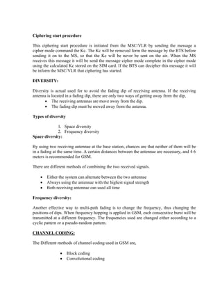
INTERFACES:
There are different types interfaces
• Air Interface (or) Um Interfaces]
Interface between the MS and BTS
• Abis Interface
Interface between the BTS and BSC
• A Interface
Interface between the BSC and MSC
Um Abis A
MS BTS BSC MSC
TRAFFIC CASES
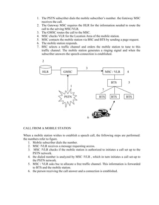
CALL TO A MOBILE STATION
The difference between making a call to a mobile subscriber and a PSTN network
subscriber is that the mobile subscriber’s location is unknown. Therefore, the mobile
station must be paged before a connection can be made. The steps in the call setup
procedure from a PSTN subscriber to a mobile station are listed below. The numbers
refer to figure](https://image.slidesharecdn.com/gsmbasics-140421124238-phpapp02/85/Gsm-basics-19-320.jpg)

- GSM was developed in 1982 by the Conference of European Postal and Telecommunications Administrations to improve digital cellular technology. It was later moved to the European Telecommunications Standards Institute. - GSM operates using FDMA and TDMA, dividing carriers into time slots to maximize voice channels in limited bandwidth. It provides wireless communication and high security against tapping. - The core network components are the BSS (including BTS and BSC), SS (including MSC, VLR, HLR, EIR), and MS. The network authenticates users based on their SIM card and supports various services like voice calls, SMS, and data.


