Downloaded 945 times


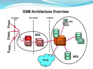
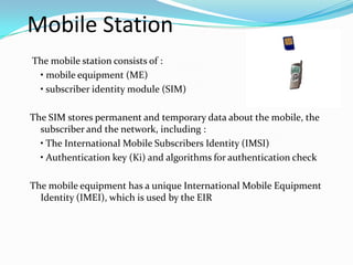
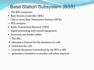
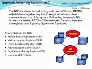

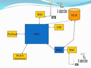

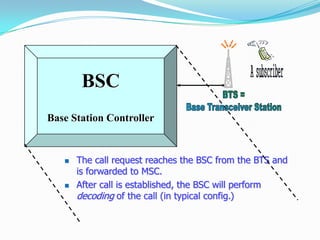
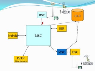
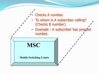
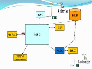

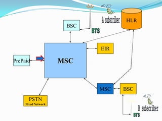
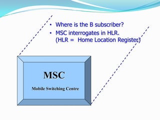
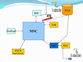
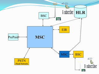

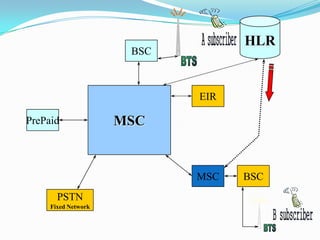

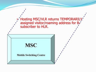
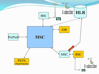
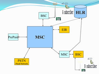

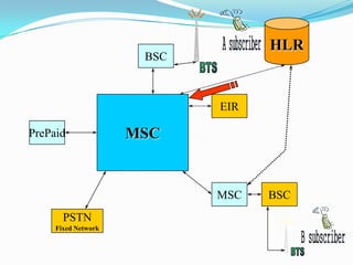
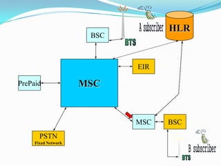
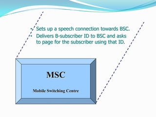
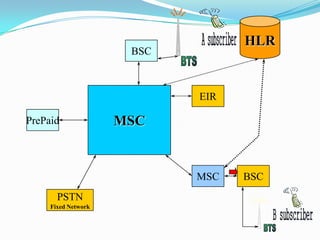
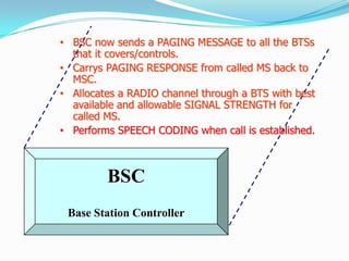
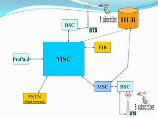


The document describes the architecture of GSM networks. It discusses the key components including the mobile station, base station subsystem (BSS), and network subsystem (NSS). The mobile station consists of mobile equipment and a subscriber identity module (SIM) card. The BSS comprises base transceiver stations and a base station controller. The NSS combines switches like the mobile switching center with databases like the home location register and visitor location register that track subscriber locations and identities.