
More Related Content
What's hot
What's hot (20)
Similar to Gsm Originating Call Flow
Similar to Gsm Originating Call Flow (20)
More from Deepak Sharma
More from Deepak Sharma (20)
Gsm Originating Call Flow
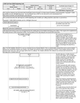
- 1. GSM Call Flow (GSM Originating Call) Cell Mobile Network Fixed Network EventStudio System Designer 4.0 Mobile Station Base Stations NSS PSTN User Mobile BSS MSC VLR PSTN 13-Sep-08 21:38 (Page 1) LEG: GSM Mobile Originated Call This sequence diagram was generated with EventStudio System Designer 4.0 (http://www.EventHelix.com/EventStudio). Copyright © 2008 EventHelix.com Inc. All Rights Reserved. The EventStudio source files for this document can be downloaded from http://www.eventhelix.com/call-flow/gsm-call-setup.zip. This scenario describes the call setup for a GSM originating call. A mobile user calling a land line subscriber is covered here. Copyright © 2000-2008 EventHelix.com Inc. All Rights Reserved. Dial the called person's number The user keys in the phone number for the landline subscriber and .. Send Button .. presses the Send button Begin RR Connection Establishment Call related information needs to be transported from the mobile phone to the Mobile Switching Center (MSC). This requires the establishment of a Radio Resource (RR) connection to MSC. The first phase of the call setup just sets up this RR connection. RR CHANNEL REQUEST RR connection establishment is RACH triggered by sending the Channel Request message. This message requests the Base Station System (BSS) for allocation for radio resources for the RR connection setup. The mobile now waits for an assignment on the Access Grant Channel (AGCH). At this point the mobile is listening to the AGCH for a reply. Note: The RR CHANNEL REQUEST is sent on a Random Access Channel (RACH). This is a slotted aloha channel that can be used at random, without any coordination between the mobiles. Any mobile can transmit on this channel whenever it wishes. If two mobiles transmit on the channel at the same time, their messages will be lost in a collision. The mobiles will detect the collision via a timeout and retransmit the message after a random back off. allocate The BSS allocates a Traffic Channel TCH (TCH) to the mobile. The TCH allocation assigns a specifies a frequency and a timeslot on that frequency. After the mobile receives this message, the mobile shall only use the specified resources for communication with the mobile network. RR IMMEDIATE ASSIGNMENT The BSS transmits the radio resource AGCH, Radio_Resource = (TCH, Frequency, assignment to the Mobile via the AGCH Timeslot), Time Correction, Frequency Correction channel. The message also contains the time and frequency corrections. The time corrections allow the mobile to time it's transmissions so that they reach the BSS only in the specified slot. The frequency corrections correct for the Doppler shift caused by the mobile's motion. Apply the time and frequency corrections Adjust the frequency and timing based on the advice from the BSS. This step is required so that transmissions from the mobile reach the base station at the precise time and with the correct frequency. Tune to the frequency and timeslot The mobile detunes from the AGCH and tunes to the specified radio channel. RR SABM + MM CM SERVICE REQUEST This is the first message that is sent TCH, SAPI = 0 after tuning to the channel. The Mobile initiates a LAPm connection with the BSC by sending a Set Asynchronous Balanced Mode (SABM) message. The service request message meant for the MSC is also sent in this message.
- 2. GSM Call Flow (GSM Originating Call) Cell Mobile Network Fixed Network EventStudio System Designer 4.0 Mobile Station Base Stations NSS PSTN User Mobile BSS MSC VLR PSTN 13-Sep-08 21:38 (Page 2) RR UA The BSS replies with Unnumbered TCH, SAPI = 0 Acknowledge (UA) to complete the LAPm setup handshake SCCP CONNECTION REQUEST + MM CM SERVICE REQUEST The BSS receives the CM Service SS7 Request message from the mobile and forms a "BSSMAP COMPLETE LAYER 3 INFORMATION". The BSS then piggy backs the message on the SCCP connection request message. LEG: Skip Authentication Procedure Check subscriber authentication MSC checks if the subscriber has been authenticated. In this case, the subscriber has already been authenticated, so the authentication procedure is skipped. Enable Ciphering BSSMAP CIPHER MODE COMMAND Since the subscriber has been successfully authenticated, the MSC initiates ciphering of the data being sent on the channel. The channel is ciphered so as so protect the call from eavesdropping. Expect ciphered data from the mobile Ciphering on the radio link is enabled in three steps. As a first step, the BSS starts expecting ciphered data from the mobile but continues to send data in clear. Since the mobile has not been informed about the ciphering, all data received from the mobile will be in error. RR CIPHERING MODE COMMAND The BSS sends the CIPHERING MODE mode = CLEAR COMMAND to the mobile. The mobile will be able to receive this message as the transmission from the BSS is still in clear. Enable ciphering for received and transmitted As a second step, the Mobile receives data the message and enables ciphering in transmit and receive directions. This action will result in all BSS data being received in error. (The BSS is still transmitting data in clear.) RR CIPHERING MODE COMPLETE Ciphering has already been enabled, so mode = CIPHERED this message is transmitted with ciphering. The BSS will receive this message as it is already expecting ciphered data in the receive direction. Enable ciphering of data transmitted to the The third and final step in the ciphering mobile handshake. The BSS enables the ciphering in transmit direction. From this point on ciphering is enabled in both directions. BSSMAP CIPHER MODE COMPLETE BSS replies back to the MSC, indicating that ciphering has been successfully enabled. RR Connection Establishment Completed At this point a connection has been setup between the Mobile and the MSC. From this point onward, the BSS is just acting as a conduit for transporting the signaling messages between the Mobile and the MSC. Call Setup CC SETUP The Mobile sends the setup message to Dialed Digits establish a voice call. The message contains the dialed digits and other information needed for call
- 3. GSM Call Flow (GSM Originating Call) Cell Mobile Network Fixed Network EventStudio System Designer 4.0 Mobile Station Base Stations NSS PSTN User Mobile BSS MSC VLR PSTN 13-Sep-08 21:38 (Page 3) establishment. CC CALL PROCEEDING The mobile is informed that the call setup is in progress. Connecting... At this point, the mobile phone displays a message on the screen to indicate that call setup is being attempted. Mode Modify allocate The MSC allocates a voice circuit on one Voice circuit towards BSS the digital trunks between the MSC and the BSS. BSSMAP ASSIGNMENT REQUEST MSC informs the BSS about the Voice circuit allocated voice circuit. The call is also switched from signaling to voice. RR CHANNEL MODE MODIFY The BSS notifies the Mobile about the changeover to voice mode. RR CHANNEL MODE MODIFY ACKNOWLEDGE Mobile acknowledges. BSSMAP ASSIGNMENT COMPLETE The BSS responds back to the MSC. ISUP INITIAL ADDRESS MESSAGE The MSC routes the call and sends the SS7, Dialed Digits call towards the called subscriber ISUP ADDRESS COMPLETE MESSAGE The PSTN indicates to the MSC that it SS7 has received all the digits and the called subscriber is being rung. CC ALERTING The MSC informs the mobile that the called subscriber is being alerted via a ring Alerting Tone ISUP ANSWER The called subscriber answers the call. SS7 CC CONNECT The MSC informs the mobile that the call has been answered. CC CONNECT ACKNOWLEDGE Acknowledge the recipt of CC CONNECT. Connected Display that the call has been connected. Conversation Speech The call has entered the conversation phase. The speech path has been setup between the mobile subscriber and the land-line subscriber. Call Release LEG: Mobile initiates call release End Button The mobile subscriber hits End to clear the call. CC DISCONNECT The mobile sends the disconnect message to the MSC. ISUP RELEASE The MSC initiates release on the PSTN SS7 side. Disconnect Voice Path The MSC disconnects the voice path and also releases the voice circuit between the BSS and the MSC. free Voice circuit towards BSS CC RELEASE The MSC informs the Mobile that it has initiated call release
- 4. GSM Call Flow (GSM Originating Call) Cell Mobile Network Fixed Network EventStudio System Designer 4.0 Mobile Station Base Stations NSS PSTN User Mobile BSS MSC VLR PSTN 13-Sep-08 21:38 (Page 4) ISUP RELEASED The MSC informs the PSTN that the call SS7 release has been completed. ISUP RELEASE COMPLETE The PSTN informs that call release has SS7 been completed at its end. CC RELEASE COMPLETE Mobile indicates that the call has been released. RR Connection Release BSSMAP CLEAR COMMAND Call release has been completed, now the RR connection is released by the MSC. RR CHANNEL RELEASE The BSS initiates RR release with the mobile. BSSMAP CLEAR COMPLETE The BSS informs the the MSC that the RR connection has been released. RR DISC The mobile sends a disconnect message to release the LAPm connection. RR UA The BSS replies with an Unnumbered Acknowledge message. free The BSS releases the TCH channel. TCH Call Released Indication Mobile goes back to the default display to indicate that call has been completely released.