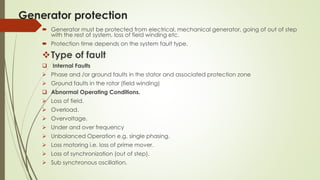
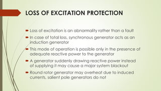
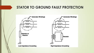
A Presentation on “generator protection”
By,
Keshar Rawal (42044)
Sabin Tandukar (42054)
Suman Shrestha (42048)
Sachin Ranjit (42056)
Karuna Adhikari ()
Aprameya Khakurel()
9th may 2014
What a Generator looks like
Generator protection
 Generator must be protected from electrical, mechanical generator, going of out of step
with the rest of system, loss of field winding etc.
 Protection time depends on the system fault type.
Type of fault
 Internal Faults
 Phase and /or ground faults in the stator and associated protection zone
 Ground faults in the rotor (field winding)
 Abnormal Operating Conditions.
 Loss of field.
 Overload.
 Overvoltage.
 Under and over frequency
 Unbalanced Operation e.g. single phasing.
 Loss motoring i.e. loss of prime mover.
 Loss of synchronization (out of step).
 Sub synchronous oscillation.
Fault Current Behavior of a
Synchronous Generator
Fault Current Behavior of a
Synchronous Generator
Percentage-differential relaying for a wye-
connected generator.
Percentage-differential relaying for a
delta-connected generator
LOSS OF EXCITATION PROTECTION
 Loss of excitation is an abnormality rather than a fault
 In case of total loss, synchronous generator acts as an
induction generator
 This mode of operation is possible only in the presence of
adequate reactive power to the generator
 A generator suddenly drawing reactive power instead
of supplying it may cause a major system blackout
 Round rotor generator may overheat due to induced
currents, salient pole generators do not
 Due to overcurrent, stator of any generator may overheat
 Automatic-quick acting relays should be used to trip the
generator’s field and main breakers
 In systems in which severe disturbances may or may not follow loss
of excitation in a given generator, the generator must sometimes
be tripped when the system does not require it, merely to be sure
that the generator will always be tripped when the system does
require it
STATOR TO GROUND FAULT PROTECTION
LOW IMPEDANCE GROUNDING
 Impedance selected to limit line-to-ground fault current
(normally between 100A and 1000A as defined by IEEE
std. 142-2007 section 1.4.3.2)
 Possible to engineer zero sequence differential
protection
 Compares the sum of three phase currents with the
neutral current
 Difference in the two currents indicates fault
ADVANTAGES
 High sensitivity
 Eliminates high transient voltages
 Limits shock to personnels
DISADVANTAGES
 High fault current flows so damage to equipment may occur if
the fault is not cleared quickly
 Line-Neutral loads cannot be used
AØ BØ
CØ
3Ø Load
HRG
480V Wye Source
N
HIGH IMPEDANCE GROUNDING
 Impedance selected to limit line-to-ground fault current
(normally < 10A as defined by IEEE std. 142-2007 section
1.4.3.1)
 Most utilized on Low Voltage
 Many 600V systems
 Some 5kV systems
 Has been utilized on up to 15kV systems (rare)
ADVANTAGES
 Eliminates high transient overvoltage's
 Limits damage to faulted equipment
 Reduces shock hazard to personnel
 Faulted circuit allowed to continue operating
DISADVANTAGES
 Nuisance alarms are possible since even small amount
of currents are detected as the result of faults.
 Line-to-neutral loads cannot be used (same as low
impedance grounding)
Over Voltage Protection(why)
 Terminal voltage controlled by an (AVR).
 If load current (I) on the generator reduces, the AVR reduce the
field current, so as to reduce open circuit emf ‘E’ to maintain
constant terminal voltage V.
 Loss of a VT fuse, incorrect operation of AVR, etc can lead to
over voltage.
 Overvoltage lead to saturation of iron, both for generator and
the unit transformer connected to it.
 Leads to large magnetizing currents, unacceptable flux patterns,
over-heating, which can damage the power apparatus.
Over voltage protection(how)
 Generator overvoltage may occur without necessarily
exceeding the V/Hz limits of the machine.
 Protection for generator overvoltage is provided with a
frequency-compensated (or frequency insensitive) overvoltage
relay.
 The relay should have both an instantaneous unit and a time
delay unit with an inverse time characteristic.
 Two definite time delay relays can also be applied
V/f Protection
 During start-up or shut down speed of generator deviate from
normal speed.
 E = 4.44f mN), over fluxing of the core occur when V/f ratio
exceeds its nominal value.
 Over voltage protection is implemented after normalizing the
terminal voltage by the frequency of the generator.
Out-of-Step Protection
 Un Synchronization of the parallel connected generator
 To detect this condition, distance relay looking into the
transformer-generator unit should be installed.
 Even a distance relay used for loss-of-field protection will
pick-up on such power swing. If the swing moves out of the
relay characteristic, before the timer runs down, then, no trip
action will be initiated.
 If the swing persists for sufficient time, the loss-of-excitation
distance relay will operate on power swing.
PROTECTION AGAINST STATOR OPEN CIRCUITS
 An open circuit or a high-resistance joint in a stator winding is very
difficult to detect before it has caused considerable damage.
 Split-phase relaying may provide such protection, but only the most
sensitive equipment will detect the trouble in its early stages.
 Negative-phase-sequence-relaying equipment for protection
against unbalanced phase
 Currents contains a sensitive alarm unit that will alert an operator to
the abnormal condition.
 It is not the practice to provide protective-relaying equipment
purposely for open circuits.
 Open circuits are most unlikely in well-constructed machines
OVERSPEED PROTECTION
 If speed governor is provided, to shut down the prime
mover.
 It should also trip the generator circuit breaker to
prevent over frequency operation of the generator.
 Over frequency relay, direct-connected centrifugal
switch may suitable.
 The over speed element should usually be adjusted to
operate at about 3% to 5% above the full-load rejection
speed.
EXTERNAL-FAULT BACK-UP PROTECTION
 Common practice to provide protection for faults
outside of the generator zone of protection.
 Voltage supervised time-overcurrent or distance relaying
may be used.
 Distance relay set to include generator step up
transformer and reach beyond, into the system.
 Time delays must be coordinated with those of the
system protection to assure that system protection will
operate before back up.
 CTs on neutral side of generator will also provide
backup protection for the generator.
BEARING-OVERHEATING PROTECTION
 Can be detected by a relay actuated by a
thermometer-type or by a resistance-temperature-
detector relay
 Or, where lubricating oil is circulated, the temperature of
the oil may be monitored if the system has provision for
giving an alarm if the oil stops flowing.
 Such protection is provided for all unattended
generators where the size or importance of the
generator warrants it.
 Such protection for attended generators is generally
only to sound an alarm.
REVERSE POWER PROTECTION
 Prevents generator from motoring on loss of prime mover
 From a system standpoint, motoring is defined as the
flow of real power into the generator acting as a motor.
 With current in the field winding, the generator will
remain in synchronism with the system and act as a
synchronous motor. If the field breaker is opened, the
generator will act as an induction motor.
 A power relay set to look into the machine is therefore
used on most units.
 The sensitivity and setting of the relay is dependent upon
the type of prime mover involved.
PROTECTION AGAINST MOTORING
 Steam Turbines:
 Overheats when the steam supply is cut off and it starts
running as a motor
 Modern condensing turbines will overheat at outputs less
than approximately 10% of rated load.
 Sensitive power directional-relaying equipment has
been widely used.
 The protective equipment should operate on somewhat
less than about 3% of rated power.
 Sufficient time delay should be provided to prevent
undesired operation on transient power reversals such as
during synchronizing or system disturbances.
 Hydraulic Turbines:
 Motoring protection may occasionally be desirable to protect
an unattended hydraulic turbine against cavitation of the
blades.
 Protection can be provided by power-directional relaying
equipment operating on motoring current less than about 2.5%
of the generator’s full-load rating.
 Gas Turbines:
 The power required to motor a gas turbine varies from 10% to
50% of full load rating, depending on turbine design and
whether it is a type that has a load turbine separate from that
used to drive the compressor.
 Protective relays should be applied based primarily on the
undesirability of imposing the motoring load on the system.
 There is usually no turbine requirement for motoring
protection.
Generator protection

Generator protection

  • 1.
    A Presentation on“generator protection” By, Keshar Rawal (42044) Sabin Tandukar (42054) Suman Shrestha (42048) Sachin Ranjit (42056) Karuna Adhikari () Aprameya Khakurel() 9th may 2014
  • 2.
    What a Generatorlooks like
  • 3.
    Generator protection  Generatormust be protected from electrical, mechanical generator, going of out of step with the rest of system, loss of field winding etc.  Protection time depends on the system fault type. Type of fault  Internal Faults  Phase and /or ground faults in the stator and associated protection zone  Ground faults in the rotor (field winding)  Abnormal Operating Conditions.  Loss of field.  Overload.  Overvoltage.  Under and over frequency  Unbalanced Operation e.g. single phasing.  Loss motoring i.e. loss of prime mover.  Loss of synchronization (out of step).  Sub synchronous oscillation.
  • 4.
    Fault Current Behaviorof a Synchronous Generator
  • 5.
    Fault Current Behaviorof a Synchronous Generator
  • 6.
    Percentage-differential relaying fora wye- connected generator.
  • 7.
    Percentage-differential relaying fora delta-connected generator
  • 8.
    LOSS OF EXCITATIONPROTECTION  Loss of excitation is an abnormality rather than a fault  In case of total loss, synchronous generator acts as an induction generator  This mode of operation is possible only in the presence of adequate reactive power to the generator  A generator suddenly drawing reactive power instead of supplying it may cause a major system blackout  Round rotor generator may overheat due to induced currents, salient pole generators do not
  • 9.
     Due toovercurrent, stator of any generator may overheat  Automatic-quick acting relays should be used to trip the generator’s field and main breakers  In systems in which severe disturbances may or may not follow loss of excitation in a given generator, the generator must sometimes be tripped when the system does not require it, merely to be sure that the generator will always be tripped when the system does require it
  • 11.
    STATOR TO GROUNDFAULT PROTECTION
  • 13.
    LOW IMPEDANCE GROUNDING Impedance selected to limit line-to-ground fault current (normally between 100A and 1000A as defined by IEEE std. 142-2007 section 1.4.3.2)  Possible to engineer zero sequence differential protection  Compares the sum of three phase currents with the neutral current  Difference in the two currents indicates fault
  • 14.
    ADVANTAGES  High sensitivity Eliminates high transient voltages  Limits shock to personnels
  • 15.
    DISADVANTAGES  High faultcurrent flows so damage to equipment may occur if the fault is not cleared quickly  Line-Neutral loads cannot be used AØ BØ CØ 3Ø Load HRG 480V Wye Source N
  • 16.
    HIGH IMPEDANCE GROUNDING Impedance selected to limit line-to-ground fault current (normally < 10A as defined by IEEE std. 142-2007 section 1.4.3.1)  Most utilized on Low Voltage  Many 600V systems  Some 5kV systems  Has been utilized on up to 15kV systems (rare)
  • 17.
    ADVANTAGES  Eliminates hightransient overvoltage's  Limits damage to faulted equipment  Reduces shock hazard to personnel  Faulted circuit allowed to continue operating
  • 18.
    DISADVANTAGES  Nuisance alarmsare possible since even small amount of currents are detected as the result of faults.  Line-to-neutral loads cannot be used (same as low impedance grounding)
  • 19.
    Over Voltage Protection(why) Terminal voltage controlled by an (AVR).  If load current (I) on the generator reduces, the AVR reduce the field current, so as to reduce open circuit emf ‘E’ to maintain constant terminal voltage V.  Loss of a VT fuse, incorrect operation of AVR, etc can lead to over voltage.  Overvoltage lead to saturation of iron, both for generator and the unit transformer connected to it.  Leads to large magnetizing currents, unacceptable flux patterns, over-heating, which can damage the power apparatus.
  • 20.
    Over voltage protection(how) Generator overvoltage may occur without necessarily exceeding the V/Hz limits of the machine.  Protection for generator overvoltage is provided with a frequency-compensated (or frequency insensitive) overvoltage relay.  The relay should have both an instantaneous unit and a time delay unit with an inverse time characteristic.  Two definite time delay relays can also be applied
  • 21.
    V/f Protection  Duringstart-up or shut down speed of generator deviate from normal speed.  E = 4.44f mN), over fluxing of the core occur when V/f ratio exceeds its nominal value.  Over voltage protection is implemented after normalizing the terminal voltage by the frequency of the generator.
  • 22.
    Out-of-Step Protection  UnSynchronization of the parallel connected generator  To detect this condition, distance relay looking into the transformer-generator unit should be installed.  Even a distance relay used for loss-of-field protection will pick-up on such power swing. If the swing moves out of the relay characteristic, before the timer runs down, then, no trip action will be initiated.  If the swing persists for sufficient time, the loss-of-excitation distance relay will operate on power swing.
  • 23.
    PROTECTION AGAINST STATOROPEN CIRCUITS  An open circuit or a high-resistance joint in a stator winding is very difficult to detect before it has caused considerable damage.  Split-phase relaying may provide such protection, but only the most sensitive equipment will detect the trouble in its early stages.  Negative-phase-sequence-relaying equipment for protection against unbalanced phase  Currents contains a sensitive alarm unit that will alert an operator to the abnormal condition.  It is not the practice to provide protective-relaying equipment purposely for open circuits.  Open circuits are most unlikely in well-constructed machines
  • 24.
    OVERSPEED PROTECTION  Ifspeed governor is provided, to shut down the prime mover.  It should also trip the generator circuit breaker to prevent over frequency operation of the generator.  Over frequency relay, direct-connected centrifugal switch may suitable.  The over speed element should usually be adjusted to operate at about 3% to 5% above the full-load rejection speed.
  • 25.
    EXTERNAL-FAULT BACK-UP PROTECTION Common practice to provide protection for faults outside of the generator zone of protection.  Voltage supervised time-overcurrent or distance relaying may be used.  Distance relay set to include generator step up transformer and reach beyond, into the system.  Time delays must be coordinated with those of the system protection to assure that system protection will operate before back up.  CTs on neutral side of generator will also provide backup protection for the generator.
  • 26.
    BEARING-OVERHEATING PROTECTION  Canbe detected by a relay actuated by a thermometer-type or by a resistance-temperature- detector relay  Or, where lubricating oil is circulated, the temperature of the oil may be monitored if the system has provision for giving an alarm if the oil stops flowing.  Such protection is provided for all unattended generators where the size or importance of the generator warrants it.  Such protection for attended generators is generally only to sound an alarm.
  • 27.
    REVERSE POWER PROTECTION Prevents generator from motoring on loss of prime mover  From a system standpoint, motoring is defined as the flow of real power into the generator acting as a motor.  With current in the field winding, the generator will remain in synchronism with the system and act as a synchronous motor. If the field breaker is opened, the generator will act as an induction motor.  A power relay set to look into the machine is therefore used on most units.  The sensitivity and setting of the relay is dependent upon the type of prime mover involved.
  • 28.
    PROTECTION AGAINST MOTORING Steam Turbines:  Overheats when the steam supply is cut off and it starts running as a motor  Modern condensing turbines will overheat at outputs less than approximately 10% of rated load.  Sensitive power directional-relaying equipment has been widely used.  The protective equipment should operate on somewhat less than about 3% of rated power.  Sufficient time delay should be provided to prevent undesired operation on transient power reversals such as during synchronizing or system disturbances.
  • 29.
     Hydraulic Turbines: Motoring protection may occasionally be desirable to protect an unattended hydraulic turbine against cavitation of the blades.  Protection can be provided by power-directional relaying equipment operating on motoring current less than about 2.5% of the generator’s full-load rating.
  • 30.
     Gas Turbines: The power required to motor a gas turbine varies from 10% to 50% of full load rating, depending on turbine design and whether it is a type that has a load turbine separate from that used to drive the compressor.  Protective relays should be applied based primarily on the undesirability of imposing the motoring load on the system.  There is usually no turbine requirement for motoring protection.