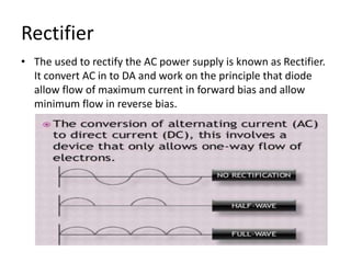
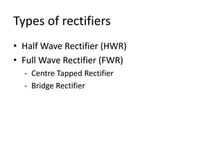
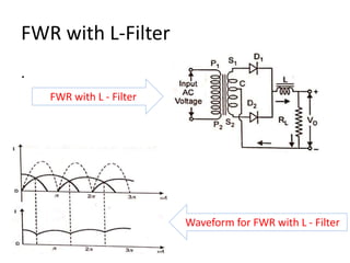
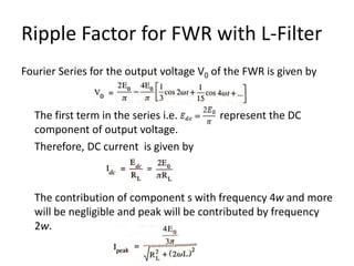
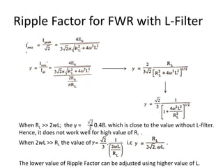
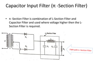
SlideShare a Scribd company logo
Rectifiers and Filter Circuits
Rakesh Kumar Sheoran
Assistant Professor in Physics
Prarambh IASE, Jhajjar (Haryana)
13/04/2020
Rectifier
• The used to rectify the AC power supply is known as Rectifier.
It convert AC in to DA and work on the principle that diode
allow flow of maximum current in forward bias and allow
minimum flow in reverse bias.
Types of rectifiers
• Half Wave Rectifier (HWR)
• Full Wave Rectifier (FWR)
- Centre Tapped Rectifier
- Bridge Rectifier
Half Wave Rectifier (HWR)
• The rectifier which pass only either (+ve or –ve) half
cycle of input AC is called HWR.
- It consists of only one diode which conduct in conduct for
half cycle (forward bias) and does not conduct for next half
cycle (reverse bias).
- Generally +ve half cycle appears in output and –ve half
cycle is cut.
- Load resistance is used for taking the output.
• Benefits
- Low power dissipation
- Maintain similar input frequency
Circuit and Wave Shape for HWR
HWR Circuit
HWR Wave Shapes
Full Wave Rectifier (FWR)
• The rectifier which pass both (+ve or –ve) half cycles
of input AC in same direction is called FWR.
- It consists of two diodes – one in Forward and other in
reverse bias at same time. The diode in forward bias give
output. After reversing the cycle of input the other diode
conduct.
- Generally +ve half cycle appears in output as it is and –ve
half cycle appear in output in inverted form.
- Load resistance is used for taking the output.
• Benefits
- High Rectification efficiency (η)
FWR (contd…)
• Full Wave Rectification can be achieved by two ways:
– Centre Tap Rectifier
– Bridge Rectifier
• Main difference
- Centre tap has high efficiency but it is hard to find the exact
centre tapping position.
- Centre Tapped Rectifier use two diodes while Bridge Rectifier
use four diodes hence it consume more power.
- Centre Tapped Rectifier operate on one diode at a time hence
voltage load on single diode remain high. Therefore, can’t be
used on high voltage.
- Bridge Rectifier use four diodes instead of two, hence not
economical.
Centre Tapped FWR (contd…)
• In Centre Tapped FWR two diodes are connected in
such a way that is diode remain in forward bias for
+ve Half Cycle of input AC and conduct. For -ve Half
Cycle of input the second diode conduct in the same
direction. Therefore the output in the ive half cycle
appear in the output as inverted form.
• Therefore, the output is obtained during both half
cycles.
Circuit and Wave Shape for Centre
Tapped FWR
FWR Circuit
FWR Wave Shapes
Bridge Rectifier
• It consists for diodes connected to form a bridge
without any centre tapping of transformer.
- Out of four diode, a pair of two diodes in series if formed.
One pair conducts for +ve Half Cycle of input and other
paid conduct during –ve Half Cycle of input. The output
during –ve half cycle is in inverted form. Hence Output is in
same direction for each cycle of input.
- As two diode in series utilized for giving output. Therefore,
the total internal resistance increase and efficiency get
reduced.
- Due to bridge shape the centre tapping is not required.
Circuit and Wave Shape for Bridge
Rectifier (BR)
BR Circuit
BR Wave Shapes
Rectification Efficiency & Ripple Factor
• Rectification Efficiency measure the %age of total
input AC converted into DC. Under best condition
(without any loss due to diodes) he Efficiency of
HWR is 40.6% and FWR is 81.2%
• Ripple Factor is measure of purity of output DC and
measures the ripple component in the output. .
Ripple Factor of HWR
Ripple Factor of FWR
Filter Circuits
• The circuits which are used to remove the ripples or
pulsating component from DC output of rectifier are
known as Filter Circuits. Such circuit are formed using
Inductor and Capacitor in Series and Parallel.
• Principle of Filter Circuit: -
– Inductor offer easy path to DC but offer resistive path to
AC.
– Capacitor offer resistive path to DC but offer easy path to
AC.
Types of Filter Circuit
• Series Inductor Filter / L-Filter)
• Shunt Capacitor filter
• Choke Inductor Filter (L– Section Filter)
• Capacitor Input Filter (π -section Filter)
HWR with L-Filter
HWR with L-Filter
Waveform for HWR with L-Filter
HWR with L-Filter (contd…)
• When current through Inductor (L) tends to increase, it oppose the
growth of current and store the excess energy in the form of
Magnetic Field.
• When current through Inductor (L) tends to decrease, it oppose the
decay of current and provide stored energy stored form the
Magnetic Field.
• Due to this the span of current flow through Load Resistance (RL)
increase.
HWR with L-Filter (contd…)
• The AC component Impedance of circuit is given by
and for DC (w=0) the Impedance is given by
• Due to high Impedance value the AC component from output will
be blocked while only DC component will be allowed.
• Let the voltage across the secondary transformer is
• As envisaged from waveform the growth of current from w=0 to w=
π/2 is opposed by Inductor (L) and similarly the decay of current
from w= π/2 to w= π is also opposed. Therefore, complete cycle in
output got elongated by θ and half cycle becomes of (π+ θ)
duration instead of π. The similar situation will be with w= π to 2π .
FWR with L-Filter
.
FWR with L - Filter
Waveform for FWR with L - Filter
Ripple Factor for FWR with L-Filter
Fourier Series for the output voltage V0 of the FWR is given by
The first term in the series i.e. represent the DC
component of output voltage.
Therefore, DC current is given by
The contribution of component s with frequency 4w and more
will be negligible and peak will be contributed by frequency
2w.
Ripple Factor for FWR with L-Filter
When RL >> 2wL; the γ = = 0.48. which is close to the value without L-filter.
Hence, it does not work well for high value of RL .
When 2wL >> RL the value of i.e. .
The lower value of Ripple Factor can be adjusted using higher value of L.
Capacitor Input Filter (π -Section Filter)
• π -Section Filter is combination of L-Section Filter and
Capacitor Filter and used where voltage higher then the L-
Section Filter is required.
Capacitor Input Filter (π -Section Filter)
• The π -Section Filter functions as series Inductor Filter except
the Capacitor Functioning. As Capacitor block the DC and
easily pass the AC; the capacitors C1 and C2 will pass the AC
and only the DC will appear through Load Resistance (RL).
Waveform for FWR with π -Section Filter
Capacitor Input Filter (π -Section Filter)
The Ripple Factor for π -Section Filter is given by
Where and are the capacitive reactance of capacitors C1
and C2 respectively. XL is the Inductive Reactance of Inductor
(L). The value of Ripple Factor (γ) can be managed by
controlling the value of Load Resistance (RL).
Assignment
1. What is rectifier? Explain, how p-n junction diode can be used as Half
Wave Rectifier. Also draw the output waveform.
2. Explain the functioning of Central Tap Full Wave Rectifier and calculate
its Ripple Factor.
3. Explain functioning of Bridge Rectifier with neat and clean diagram.
4. What is Filter Circuit? Explain following Filter Circuits and calculate
Ripple Factor for them:
(i) L-Filter
(ii) π -Section Filter
5. Explain the following terms:
(i) Ripple Factor
(ii) Rectification Efficiency
Thank You

More Related Content

What's hot

Varactor diode
Varactor diodeVaractor diode
Varactor diode
Enock Seth Nyamador
 
IGBT
IGBTIGBT
Choppers
ChoppersChoppers
Zener diodes
Zener diodesZener diodes
Zener diodes
Touqeer Jumani
 
Varactor Diode
Varactor DiodeVaractor Diode
Varactor Diode
ayesha zaheer
 
Unijunction transistor (ujt)
Unijunction transistor (ujt)Unijunction transistor (ujt)
Unijunction transistor (ujt)
Sushama Nikam
 
Diode v i characteristic
Diode v i characteristicDiode v i characteristic
Diode v i characteristic
Unsa Shakir
 
Phase Controlled Rectifiers
Phase Controlled RectifiersPhase Controlled Rectifiers
Phase Controlled Rectifiers
maneesh001
 
Clampers and clippers
Clampers and clippersClampers and clippers
Clampers and clippers
SARITHA REDDY
 
Insulated gate bipolar transistor (igbt) - basics
Insulated gate bipolar transistor (igbt) - basicsInsulated gate bipolar transistor (igbt) - basics
Insulated gate bipolar transistor (igbt) - basics
AtheenaPandian Enterprises
 
Classes of amplifiers
Classes of amplifiersClasses of amplifiers
Classes of amplifiers
Arsalan Qureshi
 
Resonance in R-L-C circuit
Resonance in R-L-C circuitResonance in R-L-C circuit
Resonance in R-L-C circuit
Siddhi Shrivas
 
Varactor diode
Varactor diodeVaractor diode
Varactor diode
Abdul Mohiz
 
Electrical presentation on pn diodes.
Electrical presentation on pn diodes.Electrical presentation on pn diodes.
Electrical presentation on pn diodes.
Atif Imam
 
Ujt
UjtUjt
Tunnel diode
Tunnel diodeTunnel diode
Tunnel diode
Sheikh Danish
 
Op amp
Op ampOp amp

What's hot (20)

Varactor diode
Varactor diodeVaractor diode
Varactor diode
 
Transistor as a switch
Transistor as a switch Transistor as a switch
Transistor as a switch
 
IGBT
IGBTIGBT
IGBT
 
Choppers
ChoppersChoppers
Choppers
 
Zener diodes
Zener diodesZener diodes
Zener diodes
 
Varactor Diode
Varactor DiodeVaractor Diode
Varactor Diode
 
Unijunction transistor (ujt)
Unijunction transistor (ujt)Unijunction transistor (ujt)
Unijunction transistor (ujt)
 
Diode v i characteristic
Diode v i characteristicDiode v i characteristic
Diode v i characteristic
 
Phase Controlled Rectifiers
Phase Controlled RectifiersPhase Controlled Rectifiers
Phase Controlled Rectifiers
 
Clampers and clippers
Clampers and clippersClampers and clippers
Clampers and clippers
 
Insulated gate bipolar transistor (igbt) - basics
Insulated gate bipolar transistor (igbt) - basicsInsulated gate bipolar transistor (igbt) - basics
Insulated gate bipolar transistor (igbt) - basics
 
Classes of amplifiers
Classes of amplifiersClasses of amplifiers
Classes of amplifiers
 
Final
FinalFinal
Final
 
Resonance in R-L-C circuit
Resonance in R-L-C circuitResonance in R-L-C circuit
Resonance in R-L-C circuit
 
Varactor diode
Varactor diodeVaractor diode
Varactor diode
 
Electrical presentation on pn diodes.
Electrical presentation on pn diodes.Electrical presentation on pn diodes.
Electrical presentation on pn diodes.
 
Ujt
UjtUjt
Ujt
 
Inductors
InductorsInductors
Inductors
 
Tunnel diode
Tunnel diodeTunnel diode
Tunnel diode
 
Op amp
Op ampOp amp
Op amp
 

Similar to Rectifiers and Filter Circuits

Chap 2 basic electronics gp 1
Chap 2 basic electronics gp 1Chap 2 basic electronics gp 1
Chap 2 basic electronics gp 1
Ankit Dubey
 
unit V rectifiers and power supplies
unit V rectifiers and power suppliesunit V rectifiers and power supplies
unit V rectifiers and power supplies
venkateshp100
 
Basiic Electronicss_chapter third-3.pptx
Basiic Electronicss_chapter third-3.pptxBasiic Electronicss_chapter third-3.pptx
Basiic Electronicss_chapter third-3.pptx
ssuser566f62
 
Rectifiers (ac dc)
Rectifiers (ac dc) Rectifiers (ac dc)
Rectifiers (ac dc)
Taimur Ijaz
 
Unit 4 Rectifiers.pptx
Unit 4 Rectifiers.pptxUnit 4 Rectifiers.pptx
Unit 4 Rectifiers.pptx
bhattparthiv23
 
1 linearpowersupply-120916082113-phpapp02
1 linearpowersupply-120916082113-phpapp021 linearpowersupply-120916082113-phpapp02
1 linearpowersupply-120916082113-phpapp02Pawar Chander
 
Prashant k11922
Prashant k11922Prashant k11922
Prashant k11922
Shivam Kumar
 
MODULE2 PRESENTATION About electronics.pptx
MODULE2 PRESENTATION About electronics.pptxMODULE2 PRESENTATION About electronics.pptx
MODULE2 PRESENTATION About electronics.pptx
alamigageraldjob33
 
Rectifiers
RectifiersRectifiers
Rectifiers
ramalakshmi54
 
Rectifiers
RectifiersRectifiers
Rectifiers
Unsa Shakir
 
Halfwave and full wave rectificaton
Halfwave and full wave rectificaton Halfwave and full wave rectificaton
Halfwave and full wave rectificaton
University of Karachi
 
Power Electronics - Phase Controlled Converters.pptx
Power Electronics - Phase Controlled Converters.pptxPower Electronics - Phase Controlled Converters.pptx
Power Electronics - Phase Controlled Converters.pptx
Poornima D
 
Oscillator
OscillatorOscillator
Oscillator
Ankit Dubey
 
ELECTRONICS DEVICES AND CIRCUITS
ELECTRONICS DEVICES AND CIRCUITSELECTRONICS DEVICES AND CIRCUITS
ELECTRONICS DEVICES AND CIRCUITS
Innovative Electronics Ideas
 
377275109-Ch-2-Uncontrolled-Rectifiers-Autosaved.pptx
377275109-Ch-2-Uncontrolled-Rectifiers-Autosaved.pptx377275109-Ch-2-Uncontrolled-Rectifiers-Autosaved.pptx
377275109-Ch-2-Uncontrolled-Rectifiers-Autosaved.pptx
priyakunduq
 
Slide_02_Chapter electrical circuit_6.pptx
Slide_02_Chapter electrical circuit_6.pptxSlide_02_Chapter electrical circuit_6.pptx
Slide_02_Chapter electrical circuit_6.pptx
moslahuddin2022
 
RECTIFIER.pptx
RECTIFIER.pptxRECTIFIER.pptx
RECTIFIER.pptx
Thanver1
 
Unit-III Electronics.pdf
Unit-III Electronics.pdfUnit-III Electronics.pdf
Unit-III Electronics.pdf
SachinNaagar4
 
POWER SUPPLY(Ashu).pptx
POWER SUPPLY(Ashu).pptxPOWER SUPPLY(Ashu).pptx
POWER SUPPLY(Ashu).pptx
Ashu Chaudhary
 
Diode Applications.pptx
Diode Applications.pptxDiode Applications.pptx
Diode Applications.pptx
ShrutiSharma485933
 

Similar to Rectifiers and Filter Circuits (20)

Chap 2 basic electronics gp 1
Chap 2 basic electronics gp 1Chap 2 basic electronics gp 1
Chap 2 basic electronics gp 1
 
unit V rectifiers and power supplies
unit V rectifiers and power suppliesunit V rectifiers and power supplies
unit V rectifiers and power supplies
 
Basiic Electronicss_chapter third-3.pptx
Basiic Electronicss_chapter third-3.pptxBasiic Electronicss_chapter third-3.pptx
Basiic Electronicss_chapter third-3.pptx
 
Rectifiers (ac dc)
Rectifiers (ac dc) Rectifiers (ac dc)
Rectifiers (ac dc)
 
Unit 4 Rectifiers.pptx
Unit 4 Rectifiers.pptxUnit 4 Rectifiers.pptx
Unit 4 Rectifiers.pptx
 
1 linearpowersupply-120916082113-phpapp02
1 linearpowersupply-120916082113-phpapp021 linearpowersupply-120916082113-phpapp02
1 linearpowersupply-120916082113-phpapp02
 
Prashant k11922
Prashant k11922Prashant k11922
Prashant k11922
 
MODULE2 PRESENTATION About electronics.pptx
MODULE2 PRESENTATION About electronics.pptxMODULE2 PRESENTATION About electronics.pptx
MODULE2 PRESENTATION About electronics.pptx
 
Rectifiers
RectifiersRectifiers
Rectifiers
 
Rectifiers
RectifiersRectifiers
Rectifiers
 
Halfwave and full wave rectificaton
Halfwave and full wave rectificaton Halfwave and full wave rectificaton
Halfwave and full wave rectificaton
 
Power Electronics - Phase Controlled Converters.pptx
Power Electronics - Phase Controlled Converters.pptxPower Electronics - Phase Controlled Converters.pptx
Power Electronics - Phase Controlled Converters.pptx
 
Oscillator
OscillatorOscillator
Oscillator
 
ELECTRONICS DEVICES AND CIRCUITS
ELECTRONICS DEVICES AND CIRCUITSELECTRONICS DEVICES AND CIRCUITS
ELECTRONICS DEVICES AND CIRCUITS
 
377275109-Ch-2-Uncontrolled-Rectifiers-Autosaved.pptx
377275109-Ch-2-Uncontrolled-Rectifiers-Autosaved.pptx377275109-Ch-2-Uncontrolled-Rectifiers-Autosaved.pptx
377275109-Ch-2-Uncontrolled-Rectifiers-Autosaved.pptx
 
Slide_02_Chapter electrical circuit_6.pptx
Slide_02_Chapter electrical circuit_6.pptxSlide_02_Chapter electrical circuit_6.pptx
Slide_02_Chapter electrical circuit_6.pptx
 
RECTIFIER.pptx
RECTIFIER.pptxRECTIFIER.pptx
RECTIFIER.pptx
 
Unit-III Electronics.pdf
Unit-III Electronics.pdfUnit-III Electronics.pdf
Unit-III Electronics.pdf
 
POWER SUPPLY(Ashu).pptx
POWER SUPPLY(Ashu).pptxPOWER SUPPLY(Ashu).pptx
POWER SUPPLY(Ashu).pptx
 
Diode Applications.pptx
Diode Applications.pptxDiode Applications.pptx
Diode Applications.pptx
 

Recently uploaded

The geography of Taylor Swift - some ideas
The geography of Taylor Swift - some ideasThe geography of Taylor Swift - some ideas
The geography of Taylor Swift - some ideas
GeoBlogs
 
Lapbook sobre os Regimes Totalitários.pdf
Lapbook sobre os Regimes Totalitários.pdfLapbook sobre os Regimes Totalitários.pdf
Lapbook sobre os Regimes Totalitários.pdf
Jean Carlos Nunes Paixão
 
Unit 2- Research Aptitude (UGC NET Paper I).pdf
Unit 2- Research Aptitude (UGC NET Paper I).pdfUnit 2- Research Aptitude (UGC NET Paper I).pdf
Unit 2- Research Aptitude (UGC NET Paper I).pdf
Thiyagu K
 
2024.06.01 Introducing a competency framework for languag learning materials ...
2024.06.01 Introducing a competency framework for languag learning materials ...2024.06.01 Introducing a competency framework for languag learning materials ...
2024.06.01 Introducing a competency framework for languag learning materials ...
Sandy Millin
 
Synthetic Fiber Construction in lab .pptx
Synthetic Fiber Construction in lab .pptxSynthetic Fiber Construction in lab .pptx
Synthetic Fiber Construction in lab .pptx
Pavel ( NSTU)
 
Thesis Statement for students diagnonsed withADHD.ppt
Thesis Statement for students diagnonsed withADHD.pptThesis Statement for students diagnonsed withADHD.ppt
Thesis Statement for students diagnonsed withADHD.ppt
EverAndrsGuerraGuerr
 
CLASS 11 CBSE B.St Project AIDS TO TRADE - INSURANCE
CLASS 11 CBSE B.St Project AIDS TO TRADE - INSURANCECLASS 11 CBSE B.St Project AIDS TO TRADE - INSURANCE
CLASS 11 CBSE B.St Project AIDS TO TRADE - INSURANCE
BhavyaRajput3
 
Introduction to AI for Nonprofits with Tapp Network
Introduction to AI for Nonprofits with Tapp NetworkIntroduction to AI for Nonprofits with Tapp Network
Introduction to AI for Nonprofits with Tapp Network
TechSoup
 
The approach at University of Liverpool.pptx
The approach at University of Liverpool.pptxThe approach at University of Liverpool.pptx
The approach at University of Liverpool.pptx
Jisc
 
CACJapan - GROUP Presentation 1- Wk 4.pdf
CACJapan - GROUP Presentation 1- Wk 4.pdfCACJapan - GROUP Presentation 1- Wk 4.pdf
CACJapan - GROUP Presentation 1- Wk 4.pdf
camakaiclarkmusic
 
Polish students' mobility in the Czech Republic
Polish students' mobility in the Czech RepublicPolish students' mobility in the Czech Republic
Polish students' mobility in the Czech Republic
Anna Sz.
 
aaaaaaaaaaaaaaaaaaaaaaaaaaaaaaaaaaaaaaaaa
aaaaaaaaaaaaaaaaaaaaaaaaaaaaaaaaaaaaaaaaaaaaaaaaaaaaaaaaaaaaaaaaaaaaaaaaaaaaaaaaaa
aaaaaaaaaaaaaaaaaaaaaaaaaaaaaaaaaaaaaaaaa
siemaillard
 
A Strategic Approach: GenAI in Education
A Strategic Approach: GenAI in EducationA Strategic Approach: GenAI in Education
A Strategic Approach: GenAI in Education
Peter Windle
 
Unit 8 - Information and Communication Technology (Paper I).pdf
Unit 8 - Information and Communication Technology (Paper I).pdfUnit 8 - Information and Communication Technology (Paper I).pdf
Unit 8 - Information and Communication Technology (Paper I).pdf
Thiyagu K
 
"Protectable subject matters, Protection in biotechnology, Protection of othe...
"Protectable subject matters, Protection in biotechnology, Protection of othe..."Protectable subject matters, Protection in biotechnology, Protection of othe...
"Protectable subject matters, Protection in biotechnology, Protection of othe...
SACHIN R KONDAGURI
 
Mule 4.6 & Java 17 Upgrade | MuleSoft Mysore Meetup #46
Mule 4.6 & Java 17 Upgrade | MuleSoft Mysore Meetup #46Mule 4.6 & Java 17 Upgrade | MuleSoft Mysore Meetup #46
Mule 4.6 & Java 17 Upgrade | MuleSoft Mysore Meetup #46
MysoreMuleSoftMeetup
 
Acetabularia Information For Class 9 .docx
Acetabularia Information For Class 9  .docxAcetabularia Information For Class 9  .docx
Acetabularia Information For Class 9 .docx
vaibhavrinwa19
 
Additional Benefits for Employee Website.pdf
Additional Benefits for Employee Website.pdfAdditional Benefits for Employee Website.pdf
Additional Benefits for Employee Website.pdf
joachimlavalley1
 
How libraries can support authors with open access requirements for UKRI fund...
How libraries can support authors with open access requirements for UKRI fund...How libraries can support authors with open access requirements for UKRI fund...
How libraries can support authors with open access requirements for UKRI fund...
Jisc
 
The Accursed House by Émile Gaboriau.pptx
The Accursed House by Émile Gaboriau.pptxThe Accursed House by Émile Gaboriau.pptx
The Accursed House by Émile Gaboriau.pptx
DhatriParmar
 

Recently uploaded (20)

The geography of Taylor Swift - some ideas
The geography of Taylor Swift - some ideasThe geography of Taylor Swift - some ideas
The geography of Taylor Swift - some ideas
 
Lapbook sobre os Regimes Totalitários.pdf
Lapbook sobre os Regimes Totalitários.pdfLapbook sobre os Regimes Totalitários.pdf
Lapbook sobre os Regimes Totalitários.pdf
 
Unit 2- Research Aptitude (UGC NET Paper I).pdf
Unit 2- Research Aptitude (UGC NET Paper I).pdfUnit 2- Research Aptitude (UGC NET Paper I).pdf
Unit 2- Research Aptitude (UGC NET Paper I).pdf
 
2024.06.01 Introducing a competency framework for languag learning materials ...
2024.06.01 Introducing a competency framework for languag learning materials ...2024.06.01 Introducing a competency framework for languag learning materials ...
2024.06.01 Introducing a competency framework for languag learning materials ...
 
Synthetic Fiber Construction in lab .pptx
Synthetic Fiber Construction in lab .pptxSynthetic Fiber Construction in lab .pptx
Synthetic Fiber Construction in lab .pptx
 
Thesis Statement for students diagnonsed withADHD.ppt
Thesis Statement for students diagnonsed withADHD.pptThesis Statement for students diagnonsed withADHD.ppt
Thesis Statement for students diagnonsed withADHD.ppt
 
CLASS 11 CBSE B.St Project AIDS TO TRADE - INSURANCE
CLASS 11 CBSE B.St Project AIDS TO TRADE - INSURANCECLASS 11 CBSE B.St Project AIDS TO TRADE - INSURANCE
CLASS 11 CBSE B.St Project AIDS TO TRADE - INSURANCE
 
Introduction to AI for Nonprofits with Tapp Network
Introduction to AI for Nonprofits with Tapp NetworkIntroduction to AI for Nonprofits with Tapp Network
Introduction to AI for Nonprofits with Tapp Network
 
The approach at University of Liverpool.pptx
The approach at University of Liverpool.pptxThe approach at University of Liverpool.pptx
The approach at University of Liverpool.pptx
 
CACJapan - GROUP Presentation 1- Wk 4.pdf
CACJapan - GROUP Presentation 1- Wk 4.pdfCACJapan - GROUP Presentation 1- Wk 4.pdf
CACJapan - GROUP Presentation 1- Wk 4.pdf
 
Polish students' mobility in the Czech Republic
Polish students' mobility in the Czech RepublicPolish students' mobility in the Czech Republic
Polish students' mobility in the Czech Republic
 
aaaaaaaaaaaaaaaaaaaaaaaaaaaaaaaaaaaaaaaaa
aaaaaaaaaaaaaaaaaaaaaaaaaaaaaaaaaaaaaaaaaaaaaaaaaaaaaaaaaaaaaaaaaaaaaaaaaaaaaaaaaa
aaaaaaaaaaaaaaaaaaaaaaaaaaaaaaaaaaaaaaaaa
 
A Strategic Approach: GenAI in Education
A Strategic Approach: GenAI in EducationA Strategic Approach: GenAI in Education
A Strategic Approach: GenAI in Education
 
Unit 8 - Information and Communication Technology (Paper I).pdf
Unit 8 - Information and Communication Technology (Paper I).pdfUnit 8 - Information and Communication Technology (Paper I).pdf
Unit 8 - Information and Communication Technology (Paper I).pdf
 
"Protectable subject matters, Protection in biotechnology, Protection of othe...
"Protectable subject matters, Protection in biotechnology, Protection of othe..."Protectable subject matters, Protection in biotechnology, Protection of othe...
"Protectable subject matters, Protection in biotechnology, Protection of othe...
 
Mule 4.6 & Java 17 Upgrade | MuleSoft Mysore Meetup #46
Mule 4.6 & Java 17 Upgrade | MuleSoft Mysore Meetup #46Mule 4.6 & Java 17 Upgrade | MuleSoft Mysore Meetup #46
Mule 4.6 & Java 17 Upgrade | MuleSoft Mysore Meetup #46
 
Acetabularia Information For Class 9 .docx
Acetabularia Information For Class 9  .docxAcetabularia Information For Class 9  .docx
Acetabularia Information For Class 9 .docx
 
Additional Benefits for Employee Website.pdf
Additional Benefits for Employee Website.pdfAdditional Benefits for Employee Website.pdf
Additional Benefits for Employee Website.pdf
 
How libraries can support authors with open access requirements for UKRI fund...
How libraries can support authors with open access requirements for UKRI fund...How libraries can support authors with open access requirements for UKRI fund...
How libraries can support authors with open access requirements for UKRI fund...
 
The Accursed House by Émile Gaboriau.pptx
The Accursed House by Émile Gaboriau.pptxThe Accursed House by Émile Gaboriau.pptx
The Accursed House by Émile Gaboriau.pptx
 

Rectifiers and Filter Circuits

  • 1. Rectifiers and Filter Circuits Rakesh Kumar Sheoran Assistant Professor in Physics Prarambh IASE, Jhajjar (Haryana) 13/04/2020
  • 2. Rectifier • The used to rectify the AC power supply is known as Rectifier. It convert AC in to DA and work on the principle that diode allow flow of maximum current in forward bias and allow minimum flow in reverse bias.
  • 3. Types of rectifiers • Half Wave Rectifier (HWR) • Full Wave Rectifier (FWR) - Centre Tapped Rectifier - Bridge Rectifier
  • 4. Half Wave Rectifier (HWR) • The rectifier which pass only either (+ve or –ve) half cycle of input AC is called HWR. - It consists of only one diode which conduct in conduct for half cycle (forward bias) and does not conduct for next half cycle (reverse bias). - Generally +ve half cycle appears in output and –ve half cycle is cut. - Load resistance is used for taking the output. • Benefits - Low power dissipation - Maintain similar input frequency
  • 5. Circuit and Wave Shape for HWR HWR Circuit HWR Wave Shapes
  • 6. Full Wave Rectifier (FWR) • The rectifier which pass both (+ve or –ve) half cycles of input AC in same direction is called FWR. - It consists of two diodes – one in Forward and other in reverse bias at same time. The diode in forward bias give output. After reversing the cycle of input the other diode conduct. - Generally +ve half cycle appears in output as it is and –ve half cycle appear in output in inverted form. - Load resistance is used for taking the output. • Benefits - High Rectification efficiency (η)
  • 7. FWR (contd…) • Full Wave Rectification can be achieved by two ways: – Centre Tap Rectifier – Bridge Rectifier • Main difference - Centre tap has high efficiency but it is hard to find the exact centre tapping position. - Centre Tapped Rectifier use two diodes while Bridge Rectifier use four diodes hence it consume more power. - Centre Tapped Rectifier operate on one diode at a time hence voltage load on single diode remain high. Therefore, can’t be used on high voltage. - Bridge Rectifier use four diodes instead of two, hence not economical.
  • 8. Centre Tapped FWR (contd…) • In Centre Tapped FWR two diodes are connected in such a way that is diode remain in forward bias for +ve Half Cycle of input AC and conduct. For -ve Half Cycle of input the second diode conduct in the same direction. Therefore the output in the ive half cycle appear in the output as inverted form. • Therefore, the output is obtained during both half cycles.
  • 9. Circuit and Wave Shape for Centre Tapped FWR FWR Circuit FWR Wave Shapes
  • 10. Bridge Rectifier • It consists for diodes connected to form a bridge without any centre tapping of transformer. - Out of four diode, a pair of two diodes in series if formed. One pair conducts for +ve Half Cycle of input and other paid conduct during –ve Half Cycle of input. The output during –ve half cycle is in inverted form. Hence Output is in same direction for each cycle of input. - As two diode in series utilized for giving output. Therefore, the total internal resistance increase and efficiency get reduced. - Due to bridge shape the centre tapping is not required.
  • 11. Circuit and Wave Shape for Bridge Rectifier (BR) BR Circuit BR Wave Shapes
  • 12. Rectification Efficiency & Ripple Factor • Rectification Efficiency measure the %age of total input AC converted into DC. Under best condition (without any loss due to diodes) he Efficiency of HWR is 40.6% and FWR is 81.2% • Ripple Factor is measure of purity of output DC and measures the ripple component in the output. .
  • 13. Rectification Efficiency & Ripple Factor • Rectification Efficiency measure the %age of total input AC converted into DC. Under best condition (without any loss due to diodes) he Efficiency of HWR is 40.6% and FWR is 81.2% • Ripple Factor is measure of purity of output DC and measures the ripple component in the output. .
  • 16. Filter Circuits • The circuits which are used to remove the ripples or pulsating component from DC output of rectifier are known as Filter Circuits. Such circuit are formed using Inductor and Capacitor in Series and Parallel. • Principle of Filter Circuit: - – Inductor offer easy path to DC but offer resistive path to AC. – Capacitor offer resistive path to DC but offer easy path to AC.
  • 17. Types of Filter Circuit • Series Inductor Filter / L-Filter) • Shunt Capacitor filter • Choke Inductor Filter (L– Section Filter) • Capacitor Input Filter (π -section Filter)
  • 18. HWR with L-Filter HWR with L-Filter Waveform for HWR with L-Filter
  • 19. HWR with L-Filter (contd…) • When current through Inductor (L) tends to increase, it oppose the growth of current and store the excess energy in the form of Magnetic Field. • When current through Inductor (L) tends to decrease, it oppose the decay of current and provide stored energy stored form the Magnetic Field. • Due to this the span of current flow through Load Resistance (RL) increase.
  • 20. HWR with L-Filter (contd…) • The AC component Impedance of circuit is given by and for DC (w=0) the Impedance is given by • Due to high Impedance value the AC component from output will be blocked while only DC component will be allowed. • Let the voltage across the secondary transformer is • As envisaged from waveform the growth of current from w=0 to w= π/2 is opposed by Inductor (L) and similarly the decay of current from w= π/2 to w= π is also opposed. Therefore, complete cycle in output got elongated by θ and half cycle becomes of (π+ θ) duration instead of π. The similar situation will be with w= π to 2π .
  • 21. FWR with L-Filter . FWR with L - Filter Waveform for FWR with L - Filter
  • 22. Ripple Factor for FWR with L-Filter Fourier Series for the output voltage V0 of the FWR is given by The first term in the series i.e. represent the DC component of output voltage. Therefore, DC current is given by The contribution of component s with frequency 4w and more will be negligible and peak will be contributed by frequency 2w.
  • 23. Ripple Factor for FWR with L-Filter When RL >> 2wL; the γ = = 0.48. which is close to the value without L-filter. Hence, it does not work well for high value of RL . When 2wL >> RL the value of i.e. . The lower value of Ripple Factor can be adjusted using higher value of L.
  • 24. Capacitor Input Filter (π -Section Filter) • π -Section Filter is combination of L-Section Filter and Capacitor Filter and used where voltage higher then the L- Section Filter is required.
  • 25. Capacitor Input Filter (π -Section Filter) • The π -Section Filter functions as series Inductor Filter except the Capacitor Functioning. As Capacitor block the DC and easily pass the AC; the capacitors C1 and C2 will pass the AC and only the DC will appear through Load Resistance (RL). Waveform for FWR with π -Section Filter
  • 26. Capacitor Input Filter (π -Section Filter) The Ripple Factor for π -Section Filter is given by Where and are the capacitive reactance of capacitors C1 and C2 respectively. XL is the Inductive Reactance of Inductor (L). The value of Ripple Factor (γ) can be managed by controlling the value of Load Resistance (RL).
  • 27. Assignment 1. What is rectifier? Explain, how p-n junction diode can be used as Half Wave Rectifier. Also draw the output waveform. 2. Explain the functioning of Central Tap Full Wave Rectifier and calculate its Ripple Factor. 3. Explain functioning of Bridge Rectifier with neat and clean diagram. 4. What is Filter Circuit? Explain following Filter Circuits and calculate Ripple Factor for them: (i) L-Filter (ii) π -Section Filter 5. Explain the following terms: (i) Ripple Factor (ii) Rectification Efficiency