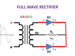
RECTIFIER
What is Rectifier?
 A rectifier is an electrical device that converts alternating
current(AC) to direct current(DC).
This process is known as rectification.
Its also called Converters.
AC Voltage Pulsated DC Voltage
Rectifier
Diode Based Rectifiers
Half Wave Rectifier Full Wave Rectifier
Bridge Type Centre Tap Transformer
Type
Types of Rectifier
Half Wave Rectifier (HWR)
Half-wave rectifiers are used to convert AC
voltage to DC voltage, and it required a
single diode to construct the circuit.
The diode only conducts when the anode is
positive with respect to cathode, the current will
flows only during the positive half cycle of the input
voltage i.e., current flow in one direction.
Half Wave Rectifier (HWR)
D
RL
v(t) = Vmsinωt vo(t)
D=ON D=OFF D=ON
Working of half wave rectifier
 AC voltage is applied to the primary winding of
the step-down transformer which step-down to
low voltage at the secondary winding which will
be applied to the diode.
During the positive half cycle of the AC voltage,
the diode will be forward biased and the current
flows through the diode.
During the negative half cycle of the AC voltage,
the diode will be reverse biased and the flow of
current will be blocked.
v(t)
time
0 5 10 15 20
+
-
Working of HWR At time t=0 sec
Phase Potential = 0 Volts
Neutral Potential =0 Volts
A K
0V 0V
VA=VK
Diode Reverse Bias.
Diode act as an OFF switch
D
RL
230V,50Hz
AC Supply
A K
P
N
NO OUTPUT VOLTAGE
vo(t)
D
RL
230V,50Hz
AC Supply
A K
P
N
v(t)
time
0 5 10 15 20
+325V
-
Working of HWR At time t=5 msec
Phase Potential = 325Volts
Neutral Potential =0 Volts
A K
325V 0V
VA > VK
Diode is forward biased
Diode act as an ON switch
D
RL
230V,50Hz
AC Supply
A K
P
N
OUTPUT VOLTAGE IS PRESENT
vo(t)
D
RL
230V,50Hz
AC Supply
A K
P
N
v(t)
time
0 5 10 15 20
+
-
Working of HWR At time t=10 msec
Phase Potential = 0 Volts
Neutral Potential =0 Volts
A K
0V 0V
VA=VK
Diode Reverse Bias.
Diode act as an OFF switch
D
RL
230V,50Hz
AC Supply
A K
P
N
NO OUTPUT VOLTAGE
vo(t)
D
RL
230V,50Hz
AC Supply
A K
P
N
v(t)
time
0 5 10 15 20
+
-
Working of HWR At time t=15 msec
Phase Potential = -325 Volts
Neutral Potential =0 Volts
A K
-325 V 0V
VA<VK
Diode Reverse Bias.
Diode act as an OFF switch
D
RL
230V,50Hz
AC Supply
A K
P
N
NO OUTPUT VOLTAGE
vo(t)
D
RL
230V,50Hz
AC Supply
A K
P
N
Graphical representation
• Vin Input Voltage (Sinusoidal Waveform)
• Vout  Output Voltage (rectified output half
wave)
HWR OUTPUT WAVEFORMS
180 360 540 720
180 360 540 720
0
0
D-ON D-ON D-ON
D-OFF D-OFF
Half Wave Rectifier With Filter
vo(t)
D
RL
230V,50Hz
AC Supply
A K
P
N
C
Vavg
time
Half wave rectifier
Advantage:
 Simple in circuit construction.
 Cost efficient.
Disadvantage:
 Filters are required to get pure DC.
 AC supply delivers power during half cycle only. So
output is low.
 Ripple factor is quite high (RF=1.21) than full wave
rectifier
 Efficiency is 40.6% only.
Full wave rectifier
A Full Wave Rectifier is a circuit, which
converts an ac voltage into a pulsating dc
voltage using both half cycles of the applied ac
voltage.
It uses two diodes of which one conducts
during one half cycle while the other conducts
during the other half cycle of the applied ac
voltage.
Full wave rectifier
Classification full wave rectifiers into,
Centre-tapped Full Wave Rectifier
Full Wave Bridge Rectifier
Full wave rectifier with center-tapped
transformer
Centre-tapped Transformer:
 It is a normal transformer with slight
modification.
It has an addition wire connected to the exact
centre of the secondary winding.
This type of construction divides the AC voltage
into two equal and opposite voltages namely +Ve
voltage (Va) and -Ve voltage (Vb).
The total output voltage is,
Full wave rectifier with center-tapped
transformer
FULL WAVE RECTIFIER
A full wave rectifier is defined as a type of rectifier that
converts both halves of each cycle of an
alternating wave (AC signal) into a pulsating DC signal
FULL WAVE RECTIFIER
Center tap Transformer Based FWR
What is Centre Tap Transformer?
N2/2
N2/2
N2 TURNS
N1 TURNS N1 TURNS
Center tap Transformer
100 Volts
100 Volts
1:1
50 Volts
50 Volts
100 Volts
1:0.5:0.5
Behavior of Center tap Transformer
with AC Supply
1:0.5:0.5
Vm
Vm / 2
-Vm / 2
-Vm
Behavior of Center tap Transformer
with AC Supply
1:0.5:0.5
+
+
-
-
+
+
-
-
0 V
FULL WAVE RECTIFIER
1:0.5:0.5
P
N
0V
D1
D2
RL
A
A
K
K
vo(t)
FULL WAVE RECTIFIER
When applying an AC voltage to the input
transformer.
 During the positive half-cycle of the AC voltage,
terminal 1 will be positive, centre-tap will be at
zero potential and terminal 2 will be negative
potential.
This will lead to forward bias in diode D1 and
cause current to flow through it. (i.e., D1
Conducts)
During this time, diode D2 is in reverse bias and
will block current through it.
During Positive Half Cycle
D1-ON & D2-OFF
D2-OFF
1:0.5:0.5
P
N
0V
D1-ON
RL
+
-
A K
K
A
Note the Current Direction
During the negative half-cycle of the input AC
voltage, terminal 2 will become positive with
relative to terminal 2 and centre-tap.
This will lead to forward bias in diode D2 and
cause current to flow through it. (i.e., D2
Conducts)
During this time, diode D1 is in reverse bias
and will block current through it.
During Negative Half Cycle
D1-OFF & D2-ON
D2-ON
1:0.5:0.5
P
N
0V
D1-OFF
RL
+
- A K
K
A
Note the Current Direction
Waveforms
D1-ON D1-ON
D2-ON D2-ON
DC OUTPUT
VOLTAGE
INPUT
AC VOLTAGE
Vm / 2 Vm / 2
Vm / 2
Vm / 2
Vm
-Vm
FWR with Filter
1:0.5:0.5
P
N
0V
D1
D2
RL
A
A
K
K
vo(t)
FWR Output with Filter
Vm / 2
Full Wave Bridge Rectifier
Diodes namely A, B, C and D
which form a bridge circuit
as shown.
BRIDGE RECTIFIER
RL
vs
D1 D2
D3
D4
P N
BRIDGE RECTIFIER – WORKING
During Positive Half Cycle
RL
vs
D1 D2
D3
D4
P N
+ 0V
+ : high potential
D1,D3 – ON
D2,D4 – OFF
vo(t)
Vm
Vm
LOOK AT THE CURRENT
DIRECTION
A
K
BRIDGE RECTIFIER – WORKING
During Negative Half Cycle
RL
vs
D1 D2
D3
D4
P N
- 0V
+ : high potential
D1,D3 – OFF
D2,D4 – ON
vo(t)
Vm
Vm
LOOK AT THE CURRENT
DIRECTION
A
K
Full wave rectifier
Advantages:
 Efficiency is higher (ɳ =81.2%)
 Low power loss because no voltage signal is
wasted in the rectification process.
Produces large DC power output
Ripple factor is less.
Disadvantages:
The centre-tapped rectifier is more expensive
than half-wave rectifier and tends to occupy a lot
of space.
Peak Inverse Voltage(PIV) rating of diode is higher.
Application of rectifier
Battery Charger
DC Power Supply
DC welder
DC Motor Drive
Comparison of Rectifiers

4. Rectifier.pptx

  • 1.
  • 2.
    What is Rectifier? A rectifier is an electrical device that converts alternating current(AC) to direct current(DC). This process is known as rectification. Its also called Converters. AC Voltage Pulsated DC Voltage Rectifier
  • 3.
    Diode Based Rectifiers HalfWave Rectifier Full Wave Rectifier Bridge Type Centre Tap Transformer Type
  • 4.
  • 5.
    Half Wave Rectifier(HWR) Half-wave rectifiers are used to convert AC voltage to DC voltage, and it required a single diode to construct the circuit. The diode only conducts when the anode is positive with respect to cathode, the current will flows only during the positive half cycle of the input voltage i.e., current flow in one direction.
  • 6.
    Half Wave Rectifier(HWR) D RL v(t) = Vmsinωt vo(t) D=ON D=OFF D=ON
  • 7.
    Working of halfwave rectifier  AC voltage is applied to the primary winding of the step-down transformer which step-down to low voltage at the secondary winding which will be applied to the diode. During the positive half cycle of the AC voltage, the diode will be forward biased and the current flows through the diode. During the negative half cycle of the AC voltage, the diode will be reverse biased and the flow of current will be blocked.
  • 8.
    v(t) time 0 5 1015 20 + - Working of HWR At time t=0 sec Phase Potential = 0 Volts Neutral Potential =0 Volts A K 0V 0V VA=VK Diode Reverse Bias. Diode act as an OFF switch D RL 230V,50Hz AC Supply A K P N NO OUTPUT VOLTAGE vo(t) D RL 230V,50Hz AC Supply A K P N
  • 9.
    v(t) time 0 5 1015 20 +325V - Working of HWR At time t=5 msec Phase Potential = 325Volts Neutral Potential =0 Volts A K 325V 0V VA > VK Diode is forward biased Diode act as an ON switch D RL 230V,50Hz AC Supply A K P N OUTPUT VOLTAGE IS PRESENT vo(t) D RL 230V,50Hz AC Supply A K P N
  • 10.
    v(t) time 0 5 1015 20 + - Working of HWR At time t=10 msec Phase Potential = 0 Volts Neutral Potential =0 Volts A K 0V 0V VA=VK Diode Reverse Bias. Diode act as an OFF switch D RL 230V,50Hz AC Supply A K P N NO OUTPUT VOLTAGE vo(t) D RL 230V,50Hz AC Supply A K P N
  • 11.
    v(t) time 0 5 1015 20 + - Working of HWR At time t=15 msec Phase Potential = -325 Volts Neutral Potential =0 Volts A K -325 V 0V VA<VK Diode Reverse Bias. Diode act as an OFF switch D RL 230V,50Hz AC Supply A K P N NO OUTPUT VOLTAGE vo(t) D RL 230V,50Hz AC Supply A K P N
  • 12.
    Graphical representation • VinInput Voltage (Sinusoidal Waveform) • Vout  Output Voltage (rectified output half wave)
  • 13.
    HWR OUTPUT WAVEFORMS 180360 540 720 180 360 540 720 0 0 D-ON D-ON D-ON D-OFF D-OFF
  • 14.
    Half Wave RectifierWith Filter vo(t) D RL 230V,50Hz AC Supply A K P N C Vavg time
  • 15.
    Half wave rectifier Advantage: Simple in circuit construction.  Cost efficient. Disadvantage:  Filters are required to get pure DC.  AC supply delivers power during half cycle only. So output is low.  Ripple factor is quite high (RF=1.21) than full wave rectifier  Efficiency is 40.6% only.
  • 16.
    Full wave rectifier AFull Wave Rectifier is a circuit, which converts an ac voltage into a pulsating dc voltage using both half cycles of the applied ac voltage. It uses two diodes of which one conducts during one half cycle while the other conducts during the other half cycle of the applied ac voltage.
  • 17.
    Full wave rectifier Classificationfull wave rectifiers into, Centre-tapped Full Wave Rectifier Full Wave Bridge Rectifier
  • 18.
    Full wave rectifierwith center-tapped transformer Centre-tapped Transformer:  It is a normal transformer with slight modification. It has an addition wire connected to the exact centre of the secondary winding. This type of construction divides the AC voltage into two equal and opposite voltages namely +Ve voltage (Va) and -Ve voltage (Vb). The total output voltage is,
  • 19.
    Full wave rectifierwith center-tapped transformer
  • 20.
    FULL WAVE RECTIFIER Afull wave rectifier is defined as a type of rectifier that converts both halves of each cycle of an alternating wave (AC signal) into a pulsating DC signal
  • 21.
    FULL WAVE RECTIFIER Centertap Transformer Based FWR What is Centre Tap Transformer? N2/2 N2/2 N2 TURNS N1 TURNS N1 TURNS
  • 22.
    Center tap Transformer 100Volts 100 Volts 1:1 50 Volts 50 Volts 100 Volts 1:0.5:0.5
  • 23.
    Behavior of Centertap Transformer with AC Supply 1:0.5:0.5 Vm Vm / 2 -Vm / 2 -Vm
  • 24.
    Behavior of Centertap Transformer with AC Supply 1:0.5:0.5 + + - - + + - - 0 V
  • 25.
  • 26.
    FULL WAVE RECTIFIER Whenapplying an AC voltage to the input transformer.  During the positive half-cycle of the AC voltage, terminal 1 will be positive, centre-tap will be at zero potential and terminal 2 will be negative potential. This will lead to forward bias in diode D1 and cause current to flow through it. (i.e., D1 Conducts) During this time, diode D2 is in reverse bias and will block current through it.
  • 27.
    During Positive HalfCycle D1-ON & D2-OFF D2-OFF 1:0.5:0.5 P N 0V D1-ON RL + - A K K A Note the Current Direction
  • 28.
    During the negativehalf-cycle of the input AC voltage, terminal 2 will become positive with relative to terminal 2 and centre-tap. This will lead to forward bias in diode D2 and cause current to flow through it. (i.e., D2 Conducts) During this time, diode D1 is in reverse bias and will block current through it.
  • 29.
    During Negative HalfCycle D1-OFF & D2-ON D2-ON 1:0.5:0.5 P N 0V D1-OFF RL + - A K K A Note the Current Direction
  • 30.
    Waveforms D1-ON D1-ON D2-ON D2-ON DCOUTPUT VOLTAGE INPUT AC VOLTAGE Vm / 2 Vm / 2 Vm / 2 Vm / 2 Vm -Vm
  • 31.
  • 32.
    FWR Output withFilter Vm / 2
  • 33.
    Full Wave BridgeRectifier Diodes namely A, B, C and D which form a bridge circuit as shown.
  • 34.
  • 35.
    BRIDGE RECTIFIER –WORKING During Positive Half Cycle RL vs D1 D2 D3 D4 P N + 0V + : high potential D1,D3 – ON D2,D4 – OFF vo(t) Vm Vm LOOK AT THE CURRENT DIRECTION A K
  • 36.
    BRIDGE RECTIFIER –WORKING During Negative Half Cycle RL vs D1 D2 D3 D4 P N - 0V + : high potential D1,D3 – OFF D2,D4 – ON vo(t) Vm Vm LOOK AT THE CURRENT DIRECTION A K
  • 37.
    Full wave rectifier Advantages: Efficiency is higher (ɳ =81.2%)  Low power loss because no voltage signal is wasted in the rectification process. Produces large DC power output Ripple factor is less. Disadvantages: The centre-tapped rectifier is more expensive than half-wave rectifier and tends to occupy a lot of space. Peak Inverse Voltage(PIV) rating of diode is higher.
  • 38.
    Application of rectifier BatteryCharger DC Power Supply DC welder DC Motor Drive
  • 39.