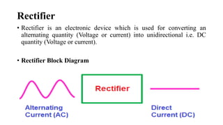
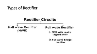
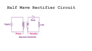
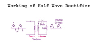
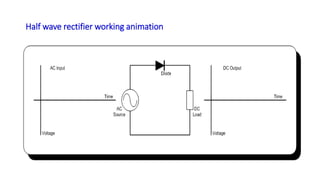
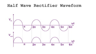
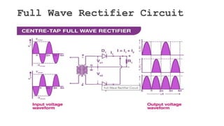
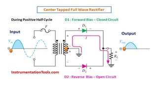
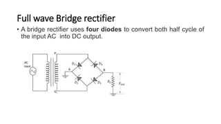
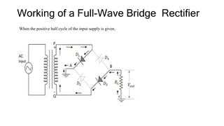
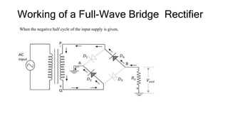
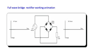
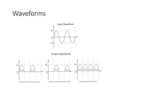
Unit 4
Topic 4.3.1 to 4.3.3
Rectifier
• Rectifier is an electronic device which is used for converting an
alternating quantity (Voltage or current) into unidirectional i.e. DC
quantity (Voltage or current).
• Rectifier Block Diagram
Rectification
• Rectification is a process of converting the alternating quantity
(voltage or current) into a corresponding direct quantity(voltage or
current).
• The input to a rectifier is AC whereas its output is unidirectional or
DC.
Types of Rectifier
Half Wave Rectifier Circuit
• A half-wave rectifier is the simplest form of the rectifier and requires
only one diode for the construction of a halfwave rectifier circuit.
• A halfwave rectifier circuit consists of three main components as
follows:
• A diode
• A transformer
• A resistive load
Half Wave Rectifier Circuit
Working of Half Wave Rectifier
Half wave rectifier working animation
Half Wave Rectifier Waveform
Advantages of Half Wave Rectifier
• Simple circuit with less number of components
• Economical at initial state. Although there is a higher cost over time
due to more power losses
Disadvantages of Half Wave
Rectifier
• Power loss
• Low output voltage
• The output contains a lot of ripples
Applications of Half Wave
Rectifier
• In day-to-day life, the half-wave rectifier is mostly used in low power
applications
Full Wave Rectifier
• A full wave rectifier is defined as a rectifier that converts the complete
cycle of alternating current into pulsating DC.
Full Wave Rectifier Circuit
Working of Centre tapped Full
Wave Rectifier
• During the positive half cycle, diode D1 is forward biased as it is
connected to the top of the secondary winding while diode D2 is
reverse biased as it is connected to the bottom of the secondary
winding. Due to this, diode D1 will conduct acting as a short circuit
and D2 will not conduct acting as an open circuit
Working of Centre tapped Full
Wave Rectifier
• During the negative half cycle, the diode D1 is reverse biased and the
diode D2 is forward biased because the top half of the secondary
circuit becomes negative and the bottom half of the circuit becomes
positive.
• Thus in a full wave rectifiers, DC voltage is obtained for both positive
and negative half cycle.
Advantages of centre tappedFull
Wave Rectifier
• The rectification efficiency of full wave rectifiers is double that of half
wave rectifiers. The efficiency of half wave rectifiers is 40.6% while
the rectification efficiency of full wave rectifiers is 81.2%.
• The ripple factor in full wave rectifiers is low hence a simple filter is
required. The value of ripple factor in full wave rectifier is 0.482 while
in half wave rectifier it is about 1.21.
• The output voltage and the output power obtained in full wave
rectifiers are higher than that obtained using half wave rectifiers.
Disadvantages of centre tapped
Full Wave Rectifier
• They need more circuit elements than the half wave rectifier which
makes, making it costlier.
Applications
• The applications of center-tapped FWR include the following.
• This rectifier is used to convert high input AC voltage to low DC
voltage.
• These types of rectifiers are used as basic components within the
power supply units due to their high efficiency.
• These are used to provide power to motors, LEDs, etc.
Full wave Bridge rectifier
• A bridge rectifier uses four diodes to convert both half cycle of
the input AC into DC output.
Working of a Full-Wave Bridge Rectifier
When the positive half cycle of the input supply is given,
Working of a Full-Wave Bridge Rectifier
When the negative half cycle of the input supply is given,
Full wave bridge rectifier working animation
Waveforms
Advantages of a Bridge Rectifier:
There are many advantages for a bridge full wave rectifier, such as −
• No need of center-tapping.
• The dc output voltage is twice that of the center-tapper FWR.
• The design of the circuit is easier with better output.
Disadvantages of Bridge Rectifier:
1.Bridge rectifier is more complex than a half-wave rectifier
2.More power loss compared to centre tapped full wave rectifier.
Applications
• The important uses of the full-wave bridge rectifier are
given below.
• Mobile phones, laptops, charger circuits.
• Uninterruptible Power Supply (UPS) circuits to convert AC to
DC.
• LED Driver Circuits.

Unit 4 Rectifiers.pptx

  • 1.
  • 2.
    Rectifier • Rectifier isan electronic device which is used for converting an alternating quantity (Voltage or current) into unidirectional i.e. DC quantity (Voltage or current). • Rectifier Block Diagram
  • 3.
    Rectification • Rectification isa process of converting the alternating quantity (voltage or current) into a corresponding direct quantity(voltage or current). • The input to a rectifier is AC whereas its output is unidirectional or DC.
  • 4.
  • 5.
    Half Wave RectifierCircuit • A half-wave rectifier is the simplest form of the rectifier and requires only one diode for the construction of a halfwave rectifier circuit. • A halfwave rectifier circuit consists of three main components as follows: • A diode • A transformer • A resistive load
  • 6.
  • 7.
    Working of HalfWave Rectifier
  • 8.
    Half wave rectifierworking animation
  • 9.
  • 10.
    Advantages of HalfWave Rectifier • Simple circuit with less number of components • Economical at initial state. Although there is a higher cost over time due to more power losses
  • 11.
    Disadvantages of HalfWave Rectifier • Power loss • Low output voltage • The output contains a lot of ripples
  • 12.
    Applications of HalfWave Rectifier • In day-to-day life, the half-wave rectifier is mostly used in low power applications
  • 13.
    Full Wave Rectifier •A full wave rectifier is defined as a rectifier that converts the complete cycle of alternating current into pulsating DC.
  • 14.
  • 17.
    Working of Centretapped Full Wave Rectifier • During the positive half cycle, diode D1 is forward biased as it is connected to the top of the secondary winding while diode D2 is reverse biased as it is connected to the bottom of the secondary winding. Due to this, diode D1 will conduct acting as a short circuit and D2 will not conduct acting as an open circuit
  • 18.
    Working of Centretapped Full Wave Rectifier • During the negative half cycle, the diode D1 is reverse biased and the diode D2 is forward biased because the top half of the secondary circuit becomes negative and the bottom half of the circuit becomes positive. • Thus in a full wave rectifiers, DC voltage is obtained for both positive and negative half cycle.
  • 19.
    Advantages of centretappedFull Wave Rectifier • The rectification efficiency of full wave rectifiers is double that of half wave rectifiers. The efficiency of half wave rectifiers is 40.6% while the rectification efficiency of full wave rectifiers is 81.2%. • The ripple factor in full wave rectifiers is low hence a simple filter is required. The value of ripple factor in full wave rectifier is 0.482 while in half wave rectifier it is about 1.21. • The output voltage and the output power obtained in full wave rectifiers are higher than that obtained using half wave rectifiers.
  • 20.
    Disadvantages of centretapped Full Wave Rectifier • They need more circuit elements than the half wave rectifier which makes, making it costlier.
  • 21.
    Applications • The applicationsof center-tapped FWR include the following. • This rectifier is used to convert high input AC voltage to low DC voltage. • These types of rectifiers are used as basic components within the power supply units due to their high efficiency. • These are used to provide power to motors, LEDs, etc.
  • 22.
    Full wave Bridgerectifier • A bridge rectifier uses four diodes to convert both half cycle of the input AC into DC output.
  • 23.
    Working of aFull-Wave Bridge Rectifier When the positive half cycle of the input supply is given,
  • 24.
    Working of aFull-Wave Bridge Rectifier When the negative half cycle of the input supply is given,
  • 25.
    Full wave bridgerectifier working animation
  • 26.
  • 27.
    Advantages of aBridge Rectifier: There are many advantages for a bridge full wave rectifier, such as − • No need of center-tapping. • The dc output voltage is twice that of the center-tapper FWR. • The design of the circuit is easier with better output.
  • 28.
    Disadvantages of BridgeRectifier: 1.Bridge rectifier is more complex than a half-wave rectifier 2.More power loss compared to centre tapped full wave rectifier.
  • 29.
    Applications • The importantuses of the full-wave bridge rectifier are given below. • Mobile phones, laptops, charger circuits. • Uninterruptible Power Supply (UPS) circuits to convert AC to DC. • LED Driver Circuits.