Downloaded 221 times

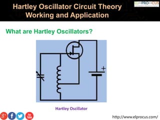


The Hartley oscillator is an electronic oscillator where the frequency is determined by a tuned circuit with capacitors and inductors, originally invented by Ralph Hartley in 1915. It can be implemented using various configurations, including transistors and operational amplifiers, to produce and stabilize sine wave outputs for applications like radio receivers. However, it has limitations, such as high harmonic content in its output and difficulty operating at low frequencies due to large inductor sizes.


