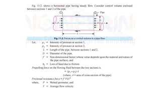
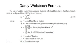
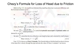
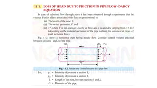
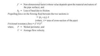
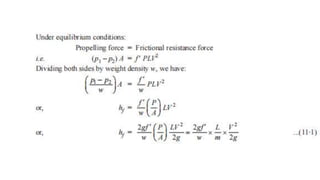
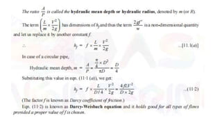
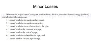
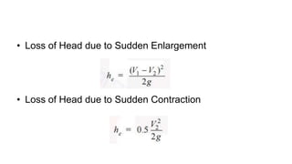
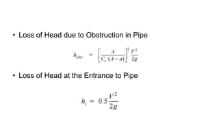
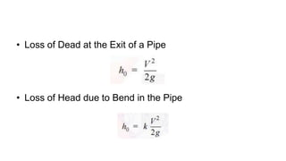
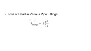
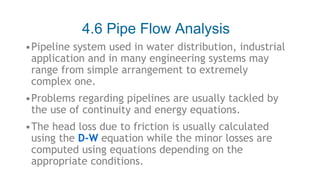
Unit 6 discusses losses in pipes, including major and minor losses. Major losses are due to friction and calculated using Darcy-Weisbach or Chezy's formulas. Minor losses are due to changes in pipe direction, size, or obstructions and are also calculated using specific formulas. The document also discusses equivalent pipes, pipes in series, pipes in parallel, and two and three reservoir pipe flow analysis problems. Head losses are calculated using friction and minor loss formulas, and continuity and energy equations are used to analyze pipe flows.
Minor losses are a major part in calculating the flow, pressure, or energy reduction in piping systems. Liquid moving through pipes carries momentum and energy due to the forces acting upon it such as pressure and gravity. Just as certain aspects of the system can increase the fluids energy, there are components of the system that act against the fluid and reduce its energy, velocity, or momentum. Friction and minor losses in pipes are major contributing factors.
Flow Through Orifices, Orifice, Types of Orifice according to Shape Size Edge Discharge, Jet, Venacontracta, Hydraulic Coefficients, Coefficient of Contraction,Coefficient of Velocity, Coefficient of Discharge, Coefficient of Resistance, Hydraulic Coefficients by Experimental Method, Discharge Through a Small rectangular orifice, Discharge Through a Large rectangular orifice, Discharge Through a Fully Drowned orifice, Discharge Through Partially Drowned orifice, Mouthpiece and its types. By Engr. M. Jalal Sarwar
PLEASE NOTE THIS IS PART-1
By Referring or said Learning This Presentation You Can Clear Your Basics Fundamental Doubts about Fluid Mechanics. In this Presentation You Will Learn about Fluid Pressure, Pressure at Point, Pascal's Law, Types Of Pressure and Pressure Measurements.
WEIRS VERSUS BERRAGE
TYPES OF WEIRS
COMPONENT PARTS OF A WEIR
CAUSES OF FAILURE OF WEIRS & THEIR REMEDIES
DESIGN CONSIDERATIONS
DESIGN FOR SURFACE FLOW
DESIGN OF BARRAGE OR WEIR
Fluid Mech. Presentation 2nd year B.Tech.shivam gautam
This Presentation covers the following topics-
Series,parallel branching pipes,
equivalent pipe length,
moody's chart
for ppt format contact me on gautam.shivam98@yahoo.com
Head losses
Major Losses
Minor Losses
Definition • Dimensional Analysis • Types • Darcy Weisbech Equation • Major Losses • Minor Losses • Causes Head Losses
3. • Head loss is loss of energy per unit weight. • Head = Energy of Fluid / Weight • Head losses can be – Kinetic Head – Potential Head – Pressure Head 6/10/2015 4Danial Gondal Head Loss
4. • Kinetic Head – K.H. = kinetic energy / Weight = v² /2g • Potential Head – P.H = Potential Energy / Weight = mgz /mg = z • Pressure Head – P.H = P/ ρ g 6/10/2015 5
5. • (P/ ρ g) + (v² /2g ) + (z) = constant • (FL-2F-1L3LT-2L-1T2) + (L2T-2L1T2)+(L) = constant • (L) + (L) + (L) = constant • As L represent height so it is dimensionally L. 6/10/2015 6 Dimensional Analysis
6. • However the equation (P/ ρ g) + (v² /2g ) + (z) = constant Is valid for Bernoulli's Inviscid flow case. As we are studying viscous flow so (P1/ ρ g) + (v1² /2g ) + (z1) = EGL1(Energy Grade Line At point 1) (P2/ ρ g) + (v2² /2g ) + (z2) = EGL2(Energy Grade Line At point 2) 6/10/2015 7 Head Loss
7. • For Inviscid Flow EGL1 - EGL2= 0 • For Viscous Flow EGL1 - EGL2= Hf 6/10/2015 8 Head Loss
8. MAJOR LOSSES IN PIPES
9. •Friction loss is the loss of energy or “head” that occurs in pipe flow due to viscous effects generated by the surface of the pipe. • Friction Loss is considered as a "major loss" •In mechanical systems such as internal combustion engines, it refers to the power lost overcoming the friction between two moving surfaces. •This energy drop is dependent on the wall shear stress (τ) between the fluid and pipe surface. 6/10/2015 10 Friction Loss
10. •The shear stress of a flow is also dependent on whether the flow is turbulent or laminar. •For turbulent flow, the pressure drop is dependent on the roughness of the surface. •In laminar flow, the roughness effects of the wall are negligible because, in turbulent flow, a thin viscous layer is formed near the pipe surface that causes a loss in energy, while in laminar flow, this viscous layer is non-existent. 6/10/2015 11 Friction Loss
11. Frictional head losses are losses due to shear stress on the pipe walls. The general equation for head loss due to friction is the Darcy-Weisbach equation, which is where f = Darcy-Weisbach friction factor, L = length of pipe, D = pipe diameter, and V = cross sectional average flow velocity.
Democratizing Fuzzing at Scale by Abhishek Aryaabh.arya
Presented at NUS: Fuzzing and Software Security Summer School 2024
This keynote talks about the democratization of fuzzing at scale, highlighting the collaboration between open source communities, academia, and industry to advance the field of fuzzing. It delves into the history of fuzzing, the development of scalable fuzzing platforms, and the empowerment of community-driven research. The talk will further discuss recent advancements leveraging AI/ML and offer insights into the future evolution of the fuzzing landscape.
Quality defects in TMT Bars, Possible causes and Potential Solutions.PrashantGoswami42
Maintaining high-quality standards in the production of TMT bars is crucial for ensuring structural integrity in construction. Addressing common defects through careful monitoring, standardized processes, and advanced technology can significantly improve the quality of TMT bars. Continuous training and adherence to quality control measures will also play a pivotal role in minimizing these defects.
Industrial Training at Shahjalal Fertilizer Company Limited (SFCL)MdTanvirMahtab2
This presentation is about the working procedure of Shahjalal Fertilizer Company Limited (SFCL). A Govt. owned Company of Bangladesh Chemical Industries Corporation under Ministry of Industries.
Student information management system project report ii.pdfKamal Acharya
Our project explains about the student management. This project mainly explains the various actions related to student details. This project shows some ease in adding, editing and deleting the student details. It also provides a less time consuming process for viewing, adding, editing and deleting the marks of the students.
COLLEGE BUS MANAGEMENT SYSTEM PROJECT REPORT.pdfKamal Acharya
The College Bus Management system is completely developed by Visual Basic .NET Version. The application is connect with most secured database language MS SQL Server. The application is develop by using best combination of front-end and back-end languages. The application is totally design like flat user interface. This flat user interface is more attractive user interface in 2017. The application is gives more important to the system functionality. The application is to manage the student’s details, driver’s details, bus details, bus route details, bus fees details and more. The application has only one unit for admin. The admin can manage the entire application. The admin can login into the application by using username and password of the admin. The application is develop for big and small colleges. It is more user friendly for non-computer person. Even they can easily learn how to manage the application within hours. The application is more secure by the admin. The system will give an effective output for the VB.Net and SQL Server given as input to the system. The compiled java program given as input to the system, after scanning the program will generate different reports. The application generates the report for users. The admin can view and download the report of the data. The application deliver the excel format reports. Because, excel formatted reports is very easy to understand the income and expense of the college bus. This application is mainly develop for windows operating system users. In 2017, 73% of people enterprises are using windows operating system. So the application will easily install for all the windows operating system users. The application-developed size is very low. The application consumes very low space in disk. Therefore, the user can allocate very minimum local disk space for this application.
Automobile Management System Project Report.pdfKamal Acharya
The proposed project is developed to manage the automobile in the automobile dealer company. The main module in this project is login, automobile management, customer management, sales, complaints and reports. The first module is the login. The automobile showroom owner should login to the project for usage. The username and password are verified and if it is correct, next form opens. If the username and password are not correct, it shows the error message.
When a customer search for a automobile, if the automobile is available, they will be taken to a page that shows the details of the automobile including automobile name, automobile ID, quantity, price etc. “Automobile Management System” is useful for maintaining automobiles, customers effectively and hence helps for establishing good relation between customer and automobile organization. It contains various customized modules for effectively maintaining automobiles and stock information accurately and safely.
When the automobile is sold to the customer, stock will be reduced automatically. When a new purchase is made, stock will be increased automatically. While selecting automobiles for sale, the proposed software will automatically check for total number of available stock of that particular item, if the total stock of that particular item is less than 5, software will notify the user to purchase the particular item.
Also when the user tries to sale items which are not in stock, the system will prompt the user that the stock is not enough. Customers of this system can search for a automobile; can purchase a automobile easily by selecting fast. On the other hand the stock of automobiles can be maintained perfectly by the automobile shop manager overcoming the drawbacks of existing system.
Final project report on grocery store management system..pdfKamal Acharya
In today’s fast-changing business environment, it’s extremely important to be able to respond to client needs in the most effective and timely manner. If your customers wish to see your business online and have instant access to your products or services.
Online Grocery Store is an e-commerce website, which retails various grocery products. This project allows viewing various products available enables registered users to purchase desired products instantly using Paytm, UPI payment processor (Instant Pay) and also can place order by using Cash on Delivery (Pay Later) option. This project provides an easy access to Administrators and Managers to view orders placed using Pay Later and Instant Pay options.
In order to develop an e-commerce website, a number of Technologies must be studied and understood. These include multi-tiered architecture, server and client-side scripting techniques, implementation technologies, programming language (such as PHP, HTML, CSS, JavaScript) and MySQL relational databases. This is a project with the objective to develop a basic website where a consumer is provided with a shopping cart website and also to know about the technologies used to develop such a website.
This document will discuss each of the underlying technologies to create and implement an e- commerce website.
Courier management system project report.pdfKamal Acharya
It is now-a-days very important for the people to send or receive articles like imported furniture, electronic items, gifts, business goods and the like. People depend vastly on different transport systems which mostly use the manual way of receiving and delivering the articles. There is no way to track the articles till they are received and there is no way to let the customer know what happened in transit, once he booked some articles. In such a situation, we need a system which completely computerizes the cargo activities including time to time tracking of the articles sent. This need is fulfilled by Courier Management System software which is online software for the cargo management people that enables them to receive the goods from a source and send them to a required destination and track their status from time to time.
Hybrid optimization of pumped hydro system and solar- Engr. Abdul-Azeez.pdffxintegritypublishin
Advancements in technology unveil a myriad of electrical and electronic breakthroughs geared towards efficiently harnessing limited resources to meet human energy demands. The optimization of hybrid solar PV panels and pumped hydro energy supply systems plays a pivotal role in utilizing natural resources effectively. This initiative not only benefits humanity but also fosters environmental sustainability. The study investigated the design optimization of these hybrid systems, focusing on understanding solar radiation patterns, identifying geographical influences on solar radiation, formulating a mathematical model for system optimization, and determining the optimal configuration of PV panels and pumped hydro storage. Through a comparative analysis approach and eight weeks of data collection, the study addressed key research questions related to solar radiation patterns and optimal system design. The findings highlighted regions with heightened solar radiation levels, showcasing substantial potential for power generation and emphasizing the system's efficiency. Optimizing system design significantly boosted power generation, promoted renewable energy utilization, and enhanced energy storage capacity. The study underscored the benefits of optimizing hybrid solar PV panels and pumped hydro energy supply systems for sustainable energy usage. Optimizing the design of solar PV panels and pumped hydro energy supply systems as examined across diverse climatic conditions in a developing country, not only enhances power generation but also improves the integration of renewable energy sources and boosts energy storage capacities, particularly beneficial for less economically prosperous regions. Additionally, the study provides valuable insights for advancing energy research in economically viable areas. Recommendations included conducting site-specific assessments, utilizing advanced modeling tools, implementing regular maintenance protocols, and enhancing communication among system components.
1. Unit-6:
Losses in Pipes
SYLLABUS:
A. Major and Minor Losses, Darcy-Wiesbach Equation, Concept of Equivalent Pipe,
Dupit’s Equation.
B. Pipes in Series, Parallel and Syphon, Two Reservoir Problems, Three Reservoir
Problems Concept of Water hammer. Surge Tanks (Function, Location and Uses).
2. FLOW THROUGH PIPE
• A pipe is a closed conduit (generally of circular section)
which is used for carrying fluids under pressure. The flow
in a pipe is termed pipe flow only when the fluid
completely fills the cross-section and there is no free
surface of fluid. The pipe running partially full (in such a
case atmospheric pressure exists inside the pipe)
behaves like an open channel.
3. LOSS OF ENERGY (OR HEAD) IN PIPES
• When water flows in a pipe, it experiences some resistance to its motion, due
to which its velocity and ultimately the head of water available is reduced.
This loss of energy (or head) is classified as follows :
A. Major Energy Losses
• This loss is due to friction.
B. Minor Energy Losses
• These losses are due to :
1. Sudden enlargement of pipe,
2. Sudden contraction of pipe,
3. Bend of pipe,
4. An obstruction in pipe,
5. Pipe fittings, etc.
4. MAJOR ENERGY LOSSES
• These losses which are due to friction are calculated by :
1. Darcy-Weisbach formula
2. Chezy’s formula.
17. Equivalent Pipe
• Equivalent pipes refer to imaginary pipes which are used
to determine the head loss and flow of discharge
considering that the flow of discharge and head loss in the
actual piping system is same as that of the equivalent
pipe. It is a technique used to decrease the large number
of attached pipe systems into an individual pipe system
such that the piping system analysis can be made easier.
• In equivalent pipe structure, the major properties of pipe
such as length of pipe, diameter of pipe and roughness
factor of pipe are required to do the analysis.
18.
19.
20.
21.
22. 4.6 Pipe Flow Analysis
•Pipeline system used in water distribution, industrial
application and in many engineering systems may
range from simple arrangement to extremely
complex one.
•Problems regarding pipelines are usually tackled by
the use of continuity and energy equations.
•The head loss due to friction is usually calculated
using the D-W equation while the minor losses are
computed using equations depending on the
appropriate conditions.
23. 4.6.2 Pipes in Series
▪ When two or more pipes of different
diameters or roughness are connected in
such a way that the fluid follows a single
flow path throughout the system, the
system represents a series pipeline.
▪ In a series pipeline the total energy loss
is the sum of the individual minor losses
and all pipe friction losses.
Pipelines in
series
24. ▪ Referring to Figure the Bernoulli equation can be written between points 1 and 2 as follows;
where P/ρg = pressure head
z = elevation head
V2/2g = velocity head
HL1-2 = total energy lost between point 1 and 2
Realizing that P1=P2=Patm, and V1=V2, then equation reduces to
z1-z2 = HL1-2
Or we can say that the different of reservoir water level is equivalent to the total head losses in the system.
The total head losses are a combination of the all the friction losses and the sum of the individual minor
losses.
HL1-2 = hfa + hfb + hentrance + hvalve + hexpansion + hexit.
Since the same discharge passes through all the pipes, the continuity equation can be written as;
Q1 = Q2
25. 4.6.3 Pipes in Parallel
Pipelines in parallel
• A combination of two or more pipes
connected between two points so that
the discharge divides at the first
junction and rejoins at the next is
known as pipes in parallel. Here the
head loss between the two junctions is
the same for all pipes.
26. ▪ Applying the continuity equation to the system;
Q1 = Qa + Qb = Q2
▪ The energy equation between point 1 and 2 can be written as;
▪ The head losses throughout the system are given by;
HL1-2=hLa = hL
▪ Equations are the governing relationships for parallel pipe line systems. The system
automatically adjusts the flow in each branch until the total system flow satisfies
these equations.