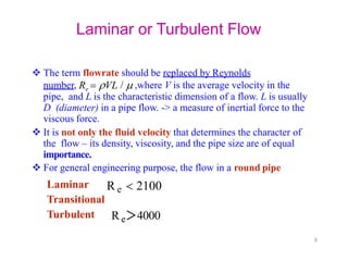
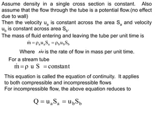
This document discusses the basic equations of fluid flow, including:
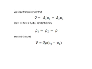
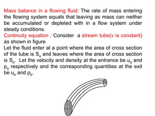
- The continuity equation, which states that the rate of mass entering a fluid system equals the rate leaving under steady conditions.
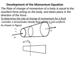
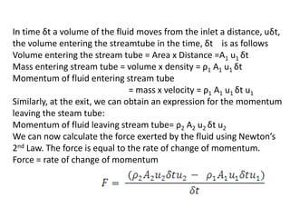
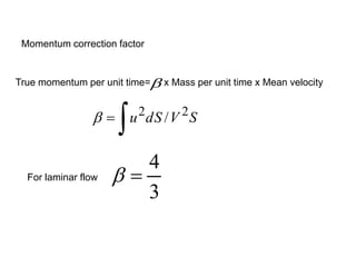
- The momentum equation, which relates the rate of change of momentum of a fluid to the forces acting on it.
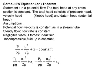
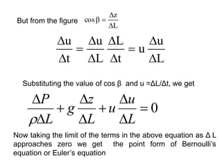
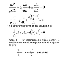
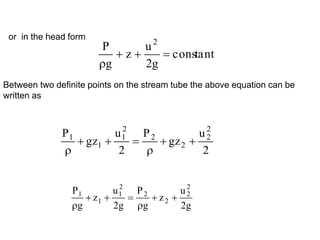
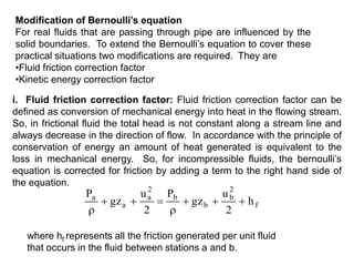
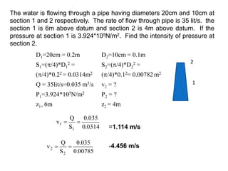
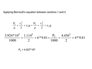
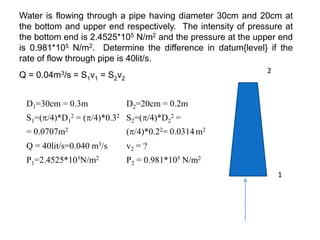
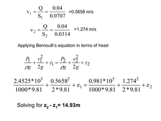
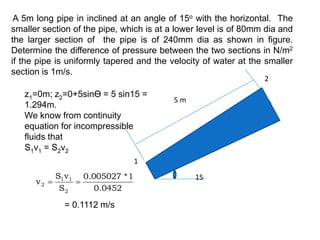
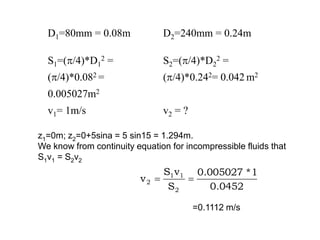
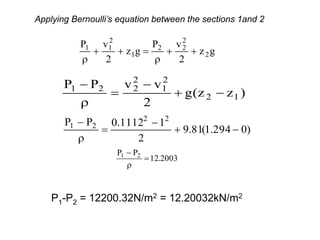
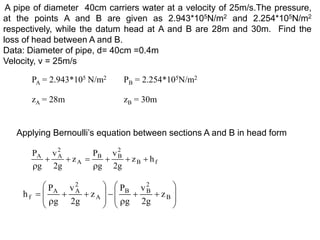
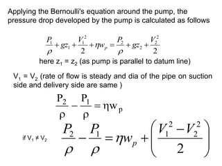
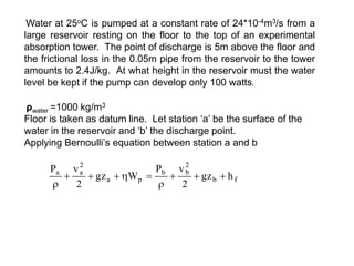
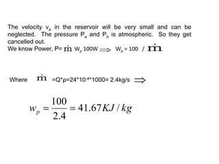
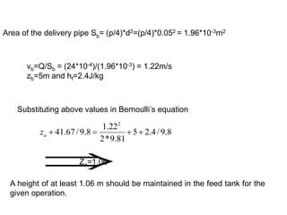
- Bernoulli's equation, which states that the total head (pressure head, velocity head, and elevation head) remains constant in an inviscid, incompressible, steady flow.
![2
0
2
R
rdr
u
V
R
S
Q
V
uS
S
u
S
u
m b
b
b
a
a
a
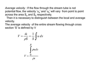
also equals the total volumetric flow rate of the fluid divided by the cross
sectional area of the conduit. That is
where Q is the volumetric flow rate, m3/s. ū and u are equal only when
the local velocity is the same at all points in area ‘S’.
The continuity equation when the velocity varies in a finite stream
tube is
Mass Velocity may be written as G, calculated by dividing the mass flow
rate by the cross sectional area of channel, [unit kg/sm2]. The mass
velocity ‘G’ can also be described as the mass current density or mass
flux, where flux is defined generally as any quantity passing through an
unit area in unit time. The average velocity ū can be described as the
volume flux of the fluid.](https://image.slidesharecdn.com/basicequationoffluidflow-240201173630-636b1b68/85/Basic-equation-of-fluid-flow-mechan-pptx-14-320.jpg)