Lecture 3 bernoulli_s_theorm_it_s_applications
•Download as PPT, PDF•
1 like•199 views

Fluid Mechanics

Recommended
More Related Content
What's hot
What's hot (20)
Similar to Lecture 3 bernoulli_s_theorm_it_s_applications
Similar to Lecture 3 bernoulli_s_theorm_it_s_applications (20)
Recently uploaded
Recently uploaded (20)
Lecture 3 bernoulli_s_theorm_it_s_applications
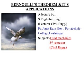
- 1. BERNOULLI’S THEOREM &IT’S APPLICATIONS A lecture by… S.Raghubir Singh (Lecturer Civil Engg.) Pt. Jagat Ram Govt. Polytechnic College,Hoshiarpur. Subject:-Fluid mechanics 3rd semester (Civil Engg.)
- 2. CONTENTS Types of fluid flow Discharge, Continuity Equation Types of Energies/heads of Ideal fluid • Potential Energy/head • Kinetic Energy/ head • Pressure Energy/ head Bernoulli’s theorem:-Assumptions, Limitations Applications of Bernoulli’s theorem : • Venturimeter • Orificemeter • Pitot Tube
- 3. Types of Fluid Flow The fluid in motion depends on various fluid properties like temperature, density, velocity and pressure. Based on these properties, the fluid can be classified as : 1. Steady and unsteady flow 2. Uniform and non- uniform flow 3. Laminar and turbulent flow
- 4. STEADY FLOW • Steady flow is defined as the type of flow in which the fluid properties like pressure,density and velocity at a point do not change with time. Mathematically, ( v/ t ) = 0 ( p/ t ) = 0 ( / t ) = 0 Example : Flow through a pipeline under constant head.
- 5. STEADY FLOW
- 6. UNSTEADY FLOW • UnSteady flow is defined as the type of flow in which the fluid properties like pressure,density and velocity at a point change with time. Mathematically, ( v/ t ) 0 ( p/ t ) 0 ( / t ) 0 Example : Flow through a pipeline when a valve is opened or closed gradually.
- 7. STEADY FLOW CHANGING INTO UNSTEADY ONE
- 8. UNIFORM FLOW Uniform flow is that type of flow in which the velocity of flow of a fluid is constant at any section in the path of flow of fluid. Mathematically, ( v/ s ) = 0 , t is constant where v = change of velocity s = change in displacement Example :- Flow of a water through a pipeline of uniform diameter.
- 9. UNIFORM FLOW
- 10. NON-UNIFORM FLOW Non-Uniform flow is that type of flow in which the velocity of flow of a fluid is not constant at any section in the path of flow of fluid. Mathematically, ( v/ s ) 0 , t is constant where v = change of velocity s = change in displacement Example :- Flow of a water through a pipeline of variable diameter.
- 11. LAMINAR FLOW • A flow is said to be laminar if each particle fluid has a definite path and the path of one particle does not cross the path of any other particle. • It is also called streamline or viscous flow. • Examples :- Flow of blood in veins and arteries,Ground water flow.
- 12. TURBULENT FLOW • A flow is said to be turbulent if the fluid particles do not have a definite path and path of one particle crosses the path of other particles during flow. • It is also called non-laminar flow. The fluid particles move in zigzag way. • Examples :- Flow of a river water, flow of petrol through a pipeline.
- 13. CHANGE OF LAMINAR FLOW INTO TURBULENT FLOW
- 14. DISCHARGE Discharge can be defined as the quantity of a fluid flowing per second through a section of a pipe or channel. It is generally denoted by Q. Let A = Cross-sectional area of the pipe. V = Average velocity of the liquid. Discharge, Q = Area x Average velocity Q = A x V Units of Discharge : m3/sec
- 15. CONTINUITY EQUATION Continuity equation states that if no fluid is added or removed from the pipe in any length then the mass passing across different sections shall be same.This equation is based on the principle of Conservation of mass. Mathematically, Continuity equation can be written as : A1V1 = A2V2
- 16. CONTINUITY EQUATION Considering two cross sections of a tapering pipe. Let V1 =Average velocity at Section 1-1 A1= Area of pipe at Section 1-1 1 = Density at section 1-1 and V2,A2, 2 are the values at Section 2-2. Section 1-1 Section 2-2
- 17. CONTINUITY EQUATION Total Quantity of fluid mass passing through sec 1-1= 1 A1 V1 Total Quantity of fluid mass passing through sec 2-2= 2 A2 V2 According to law of conservation of mass, 1 A1 V1= 2 A2 V2 ------------(1) For incompressible fluids, 1 = 2 From continuity equation (1) A1 V1= A2 V2
- 18. ENERGIES OF AN IDEAL FLUID There are three types of energies of the flowing fluids: 1.Kinetic Energy (E) 2.Potential Energy (U) 3.Pressure Energy (P) Based on above three types of energies, we have three different types of heads of flowing fluids namely Kinetic head,potential head and pressure head. A head is the specific measurement of water pressure above datum(a reference from which measurements are made)
- 19. 1. KINETIC ENERGY • Kinetic energy of a fluid particle is the energy which it possesses due to its motion or velocity.e.g Waves striking at the seashore. • Kinetic head or velocity head is the kinetic energy of a fluid per unit of its weight.
- 20. KINETIC HEAD Let Mass of a fluid particle = m kg Velocity of flow of the fluid =V m/sec Kinetic Energy of the fluid particle E = 1/2 mV2 joules 1 Joule = 1J = 1 kg(m2/s2) or 1 N-m Weight of the fluid particle ,W = mg Kinetic Head or Velocity head = E/W = 1/2 mV2 mg Kinetic Head = V2 metre of the fluid 2g
- 21. 2. POTENTIAL ENERGY • Potential energy of a fluid particle is the energy which it possesses due to its position. • Potential Head is the potential energy of a fluid per unit of its weight.
- 22. POTENTIAL HEAD Let Mass of the fluid particle = ‘m’ kg Height of the fluid particle above datum line = ‘Z’ m Potential energy of the fluid particle U = m.g.Z N-m Weight of the fluid particle ,W = mg Potential Head of the fluid particle = U = m g Z W m g Potential Head = Z
- 23. 3. PRESSURE ENERGY • The energy possessed by the fluid particles by virtue of its existing pressure is called pressure energy. • Pressure head is the pressure energy of a fluid per unit of its weight.
- 24. PRESSURE HEAD Pressure Energy P in N-m = press. intensity x Volume = p x V = p x W/w since ( w = W/V) Pressure Head of the liquid= P = p x W/w W W Pressure Head P = p/w
- 25. TOTAL ENERGY/ HEAD OF A LIQUID PARTICLE IN MOTION The Total energy of a fluid particle in motion is the sum of its potential energy, kinetic energy and pressure energy Total Energy (E) = Z + V2/2g + p/w Total head of a fluid a fluid particle in motion is the sum of its potential head, kinetic head and pressure head . Total Head (H) = Z + V2/2g + p/w
- 26. BERNOULLI’S THEOREM Dr. Daniell Bernoulli (1783)
- 27. BERNOULLI’S THEOREM • This theorem states that the total energy of the fluid particle remains the same for an ideal incompressible fluid flowing from one section to another section in a continuous stream. Section 1-1 Section 2-2 Z1 Z2
- 28. BERNOULLI’S THEOREM Bernoulli’s theorem can be derived from principle of conservation of energy. ( Energy can neither be destroyed nor be created ; it can only be transformed from one state to another) Mathematically, p/w + V2/2g + Z = Constant where p/w = Pressure head V2/2g = Velocity head Z = Potential head
- 29. ASSUMPTIONS OF BERNOULLI’S THEOREM The flow is steady and continuous. The flow is along a stream line The flow is ideal and incompressible. The velocity is uniform over the section . No external force acts on the fluid except force of gravity.
- 30. LIMITATIONS OF BERNOULLI’S THEOREM The Loss of energy due to pipe friction is neglected in the Bernoulli’s equation. The loss of energy due to turbulency is not taken into account by the Bernoulli’s equation. Bernoulli’s equation does not take into consideration loss of energy due to change of direction.
- 31. LIMITATIONS OF BERNOULLI’S THEOREM In assumptions, the velocity of a liquid particle at any point across a cross-section of a pipe is assumed to be uniform but the velocity of the liquid particle is maximum at centre of a pipe and gradually decreases towards the walls of the pipe. Hence, the mean velocity of flow should have been taken into consideration.
- 33. APPLICATIONS OF BERNOULLI’S THEOREM The three important applications of Bernoulli’s theorem are :- 1. Venturimeter 2. Orificemeter 3. Pitot Tube
- 34. VENTURIMETER A Venturimeter is a device used for measuring discharge of a fluid flowing through a pipe. It is named after the Italian Engineer Venturimeter in 18th century. The working Principle of Venturimeter is based on Bernoulli’s Equation. The total energy of the fluid particle remains the same for an ideal incompressible fluid flowing from one section to another section in a continuous stream.
- 35. TYPES OF VENTURIMETER There are three types of venturimeters: 1. Horizontal venturimeter 2. Vertical venturimeter 3. Inclined venturimeter Construction of venturimeter A venturimeter basically consists of three parts:- a. Converging part b. Throat c. Diverging part (3 to 4 times longer than converging part)
- 36. HORIZONTAL VENTURIMETER Let D1 = Diameter at section 1-1 p1 = Intensity of pressure at section 1-1 V1 = Velocity of fluid at section 1-1 Z1 = Datum head at section 1-1 A1 = Area at section 1-1 and D2 , p2, V2, Z2, A2 are the corresponding values at section 2-2.
- 37. HORIZONTAL VENTURIMETER Expression of Actual discharge through venturimeter Q actual = Cd A1 A2 2gh A1 2 - A2 2 where h = difference of pressure heads at section 1-1 and section 2-2 Cd = Co-efficient of venturimeter(discharge) having value less than 1 (0.96 to 0.98 ) Due to variation of Cd venturimeters are not suitable for very low velocities.
- 38. ORIFICEMETER Orificemeter is the simple device used for measuring the discharge of a fluid through a pipe. This device is comparitively cheaper than venturimeter. The working Principle of orificemeter is also based on Bernoulli’s Equation. Orificemeter consists of a flat circular plate having a central circular hole in it called an ORIFICE.
- 39. ORIFICEMETER The diameter of the orifice varies from 0.4 to 0.8 times the diameter of pipe.(preferably 0.5 times). Expression of actual discharge through orificemeter is given by:- Q actual = Cd A0 2gh 1- (A0/A1)2 where A0 is the area of the orifice.
- 40. PITOT TUBE Pitot tube is used to measure the velocity of flow at any point in a pipe. It is a tube bent at right angles. Pitot tube works on the principle that if the velocity of flow at any point becomes zero,the pressure increases at that point.(V 1/P) Velocity at any point: V = Cv 2gh where Cv =Coefficient of Pitot tube
- 41. CONCLUSION Types of flow Continuity Equation Types of energies/ heads Bernoulli’s theorem : Assumptions,Limitations Applications of Bernoulli’s theorem : Venturimeter, Orificemeter, Pitot tube ** ** ** ** ** Dr. Daniell Bernoulli (1783)