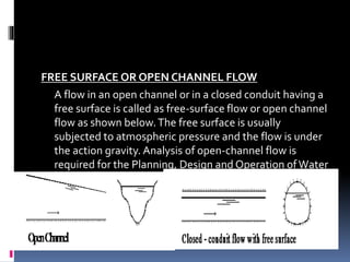
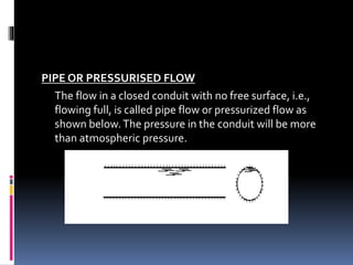
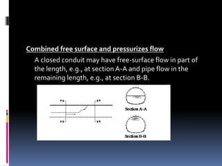
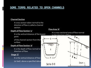
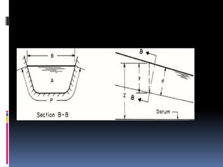
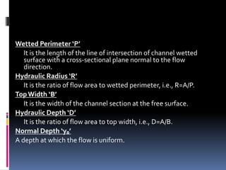
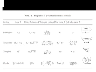
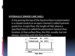
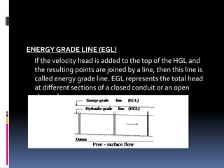
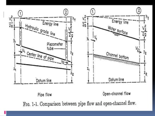
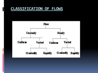
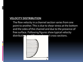
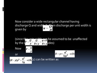
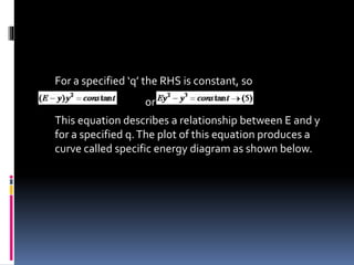
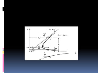
CE-422
HYDRAULICS ENGINEERING
Lecture 1
Engr.KashifHashmi cell,no 03205076452
The word ‘Hydraulics’ is derived from the
Greek word ‘Hodour’ which means water.
Thus the subject of Hydraulics may be
defined as that branch of Engineering-
Science, which deals with water whether at
rest or in motion.
Basic Definitions
CLOSED CONDUIT
A flow passage with closed top is called a closed conduit,
e.g., tunnels, pipes and aqueducts etc.
OPEN CHANNEL
A flow passage with open top is known as an open
channel, e.g., rivers, streams etc.
FREE SURFACE OR OPEN CHANNEL FLOW
A flow in an open channel or in a closed conduit having a
free surface is called as free-surface flow or open channel
flow as shown below.The free surface is usually
subjected to atmospheric pressure and the flow is under
the action gravity. Analysis of open-channel flow is
required for the Planning, Design and Operation ofWater
Resource Projects.
PIPE OR PRESSURISED FLOW
The flow in a closed conduit with no free surface, i.e.,
flowing full, is called pipe flow or pressurized flow as
shown below.The pressure in the conduit will be more
than atmospheric pressure.
Combined free surface and pressurizes flow
A closed conduit may have free-surface flow in part of
the length, e.g., at section A-A and pipe flow in the
remaining length, e.g., at section B-B.
SOME TERMS RELATED TO OPEN CHANNELS
Channel Section
A cross section taken normal to the
direction of flow is called a channel
section.
Depth of Flow Section ‘y’
It is the vertical distance of the lowest
point
of the channel section from the free
surface.
Depth of Flow Section ‘d’
It is the depth of flow normal to the
direction of flow.
Stage ‘Z’
It is the vertical distance of free surface
(or bed) above a specified datum.
Flow Area ‘A’
It is cross-sectional area of flow normal
to the direction of flow.
Wetted Perimeter ‘P’
It is the length of the line of intersection of channel wetted
surface with a cross-sectional plane normal to the flow
direction.
Hydraulic Radius ‘R’
It is the ratio of flow area to wetted perimeter, i.e., R=A/P.
TopWidth ‘B’
It is the width of the channel section at the free surface.
Hydraulic Depth ‘D’
It is the ratio of flow area to top width, i.e., D=A/B.
Normal Depth ‘y₀’
A depth at which the flow is uniform.
HYDRAULIC GRADE LINE (HGL)
A line joining the top of the liquid surface in piezometers
in a closed conduit or an open channel is called hydraulic
grade line. In pipe flow, the height of HGL above a
specified datum is called the piezometric head at that
location. In free surface flow, the HGL usually, but not
always, coincides with the free surface.
ENERGY GRADE LINE (EGL)
If the velocity head is added to the top of the HGL and
the resulting points are joined by a line, then this line is
called energy grade line. EGL represents the total head
at different sections of a closed conduit or an open
channel.
TERMINOLOGY
A channel may be natural or artificial.Various names have been used for artificial channels as follows:
Canal
A long channel having mild slope excavated in ground is called a canal.
Flume
A channel supported above ground and built of wood, metal or concrete is called a flume.
Chute
A chute is a channel having very steep bottom slope and almost vertical sides.
Tunnel
A tunnel is a channel excavated through a hill or a mountain.
Culvert
A short channel flowing partly full is known as culvert.
Prismatic Channel
A channel having the same cross section and bottom slope is referred to as a prismatic channel
Non-Prismatic Channel
A channel having varying cross section and/or bottom slope is called a non-prismatic channel.
CLASSIFICATION OF FLOWS
STEADYAND UNSTEADY FLOWS
If the flow velocity at a given point does not change with respect to time, then
the flow is called steady flow. However, if the velocity at a given location
changes with respect to time, then the flow is called unsteady flow.
UNIFORM AND NON-UNIFORM FLOWS
If the flow velocity at a given instant of time does not change within a given
length of channel, then the flow is called uniform flow. However, if the flow
velocity at a time varies with respect to distance, then the flow is called non-
uniform flow or varied flow.
GRADUALLY & RAPIDLYVARIED FLOW
If the flow depth varies at a slow rate with respect to distance, then the flow is
called gradually varied flow (GVF) whereas if the flow depth varies significantly
in a short distance then the flow is called rapidly varied flow.
LAMINAR ANDTURBULENT FLOWS
If the liquid particles appear to move in definite smooth paths and flow
appears to be as a movement of thin layers on top of each other, then
the flow is called laminar flow.
In turbulent flow, the liquid particles move in irregular paths which are
not fixed with respect to either time or space.
The value of Reynolds number (Re=VL/) determines whether the flow is
laminar or turbulent.
SUBCRITICAL, SUPERCRITICAL AND
CRITICAL FLOWS
A critical flow is defined as that for which the value of Froude number
(Fr=V/√gy) is equal to 1.
If the value of Froude number is less than 1 then the flow is called
subcritical.
If the value of Froude number is more than 1 then the flow is said to be
supercritical.
VELOCITY DISTRIBUTION
The flow velocity in a channel section varies from one
point to another.This is due to shear stress at the bottom
and the sides of the channel and due to the presence of
free surface. Following figures show typical velocity
distributions in different channel cross-sections.
Energy Coefficient
The flow velocity in a channel section usually varies from one
point to another.Therefore, the mean velocity head in a
channel section, (V ²/2g)m, is not the same as the velocity head,
V ²m/(2g), computed by using the mean flow velocity, Vm, in
which the subscript m refers to the mean values.This
difference may be taken into consideration by introducing an
energy coefficient, α known as Energy coefficient.
Momentum Cefficient
Similar to the energy coefficient, a coefficient for the
momentum transfer through a channel section may be
introduced to account for non uniform velocity distribution.
This coefficient, also called Boussinesq coefficient, is denoted
by β.
Specific Energy
Specific Energy ‘E’ is defined as
When the Energy head is referred to the bed of the
channel as datum is called Specific Energy. OR
The sum of the depth of flow and velocity head is called
Specific Energy
If velocity distribution is uniform, i.e.,  = 1 and pressure
distribution is hydrostatic then Bernoulli’s equation
reduces to
If the channel bottom is considered as datum, i.e., Z = 0
then
Now consider a wide rectangular channel having
discharge Q and width B.Then discharge per unit width is
given by
(since the unit width can be assumed to be unaffected
by the channel bed and sides)
Now
or
So equation (2) can be written as
For a specified ‘q’ the RHS is constant, so
or
This equation describes a relationship between E and y
for a specified q.The plot of this equation produces a
curve called specific energy diagram as shown below.
Some characteristics of E-y curve
 Starting form upper limb, it can be seen that initially ‘E’ reduces with ‘y’
and attains minimum value at ‘C’ and then again starts increasing with a
decrease in ‘y’.
 Equation (5) is a cubic equation having 3 roots. One of these roots is
always negative. But since depth cannot be –ive so there are only two
values of ‘y’ for a given ‘E’.These two depths are called alternate depths.
 The flow depth corresponding to ‘C’ is called critical depth denoted by
‘yc’ and the corresponding flow is called critical flow.
 A flow having depth  yc is called subcritical flow and a flow having
depth  yc is called supercritical flow.
 At critical depth Specific Energy is minimum.
 The energy value for both sub and super critical flows are always greater than
Emin.
Critical Depth
The depth of flow corresponding to the minimum
specific energy for a given ‘q’ is known as critical depth.
Critical Flow
The Flow at which Specific Energy is minimum for a given
‘q’ is known as critical flow.
Alternate Depths
The depths of flow corresponding to given specific
energy for a given ‘q’ are called alternate depths. One of
the depth is in sub critical stage and the other is in
supercritical stage.
Sub critical Flow
If the depth of flow is greater than the critical depth.
OR
If the velocity of flow is less than the critical velocity
than the flow is known as Sub critical.
Super critical Flow
If the depth of flow is less than the critical depth.
OR
If the velocity of flow is greater than the critical
velocity than the flow is known as Super critical.
 If ‘q’ varies then we get different specific energy curves
as shown below:
Engr.kashifhashmi cell no,
03205076452
APPLICATION OF CRITICAL FLOW
 The property of flow that discharge is maximum at critical depth
has been utilized to develop several flow measuring devices.
These devices are called critical-flow meters, e.g., Parshall flume,
broad-crested weir etc.
 Similarly the length of bridges or other structures on a channel
may be reduced by producing critical flow at that section.
 Critical flow may be produced in a channel by raising the channel
bottom, by reducing the channel width, or by a combination of
these measures.

Hydraulics chapter 1

  • 1.
  • 2.
    The word ‘Hydraulics’is derived from the Greek word ‘Hodour’ which means water. Thus the subject of Hydraulics may be defined as that branch of Engineering- Science, which deals with water whether at rest or in motion.
  • 3.
    Basic Definitions CLOSED CONDUIT Aflow passage with closed top is called a closed conduit, e.g., tunnels, pipes and aqueducts etc. OPEN CHANNEL A flow passage with open top is known as an open channel, e.g., rivers, streams etc.
  • 4.
    FREE SURFACE OROPEN CHANNEL FLOW A flow in an open channel or in a closed conduit having a free surface is called as free-surface flow or open channel flow as shown below.The free surface is usually subjected to atmospheric pressure and the flow is under the action gravity. Analysis of open-channel flow is required for the Planning, Design and Operation ofWater Resource Projects.
  • 5.
    PIPE OR PRESSURISEDFLOW The flow in a closed conduit with no free surface, i.e., flowing full, is called pipe flow or pressurized flow as shown below.The pressure in the conduit will be more than atmospheric pressure.
  • 6.
    Combined free surfaceand pressurizes flow A closed conduit may have free-surface flow in part of the length, e.g., at section A-A and pipe flow in the remaining length, e.g., at section B-B.
  • 7.
    SOME TERMS RELATEDTO OPEN CHANNELS Channel Section A cross section taken normal to the direction of flow is called a channel section. Depth of Flow Section ‘y’ It is the vertical distance of the lowest point of the channel section from the free surface. Depth of Flow Section ‘d’ It is the depth of flow normal to the direction of flow. Stage ‘Z’ It is the vertical distance of free surface (or bed) above a specified datum. Flow Area ‘A’ It is cross-sectional area of flow normal to the direction of flow.
  • 9.
    Wetted Perimeter ‘P’ Itis the length of the line of intersection of channel wetted surface with a cross-sectional plane normal to the flow direction. Hydraulic Radius ‘R’ It is the ratio of flow area to wetted perimeter, i.e., R=A/P. TopWidth ‘B’ It is the width of the channel section at the free surface. Hydraulic Depth ‘D’ It is the ratio of flow area to top width, i.e., D=A/B. Normal Depth ‘y₀’ A depth at which the flow is uniform.
  • 11.
    HYDRAULIC GRADE LINE(HGL) A line joining the top of the liquid surface in piezometers in a closed conduit or an open channel is called hydraulic grade line. In pipe flow, the height of HGL above a specified datum is called the piezometric head at that location. In free surface flow, the HGL usually, but not always, coincides with the free surface.
  • 12.
    ENERGY GRADE LINE(EGL) If the velocity head is added to the top of the HGL and the resulting points are joined by a line, then this line is called energy grade line. EGL represents the total head at different sections of a closed conduit or an open channel.
  • 14.
    TERMINOLOGY A channel maybe natural or artificial.Various names have been used for artificial channels as follows: Canal A long channel having mild slope excavated in ground is called a canal. Flume A channel supported above ground and built of wood, metal or concrete is called a flume. Chute A chute is a channel having very steep bottom slope and almost vertical sides. Tunnel A tunnel is a channel excavated through a hill or a mountain. Culvert A short channel flowing partly full is known as culvert. Prismatic Channel A channel having the same cross section and bottom slope is referred to as a prismatic channel Non-Prismatic Channel A channel having varying cross section and/or bottom slope is called a non-prismatic channel.
  • 15.
  • 16.
    STEADYAND UNSTEADY FLOWS Ifthe flow velocity at a given point does not change with respect to time, then the flow is called steady flow. However, if the velocity at a given location changes with respect to time, then the flow is called unsteady flow. UNIFORM AND NON-UNIFORM FLOWS If the flow velocity at a given instant of time does not change within a given length of channel, then the flow is called uniform flow. However, if the flow velocity at a time varies with respect to distance, then the flow is called non- uniform flow or varied flow. GRADUALLY & RAPIDLYVARIED FLOW If the flow depth varies at a slow rate with respect to distance, then the flow is called gradually varied flow (GVF) whereas if the flow depth varies significantly in a short distance then the flow is called rapidly varied flow.
  • 17.
    LAMINAR ANDTURBULENT FLOWS Ifthe liquid particles appear to move in definite smooth paths and flow appears to be as a movement of thin layers on top of each other, then the flow is called laminar flow. In turbulent flow, the liquid particles move in irregular paths which are not fixed with respect to either time or space. The value of Reynolds number (Re=VL/) determines whether the flow is laminar or turbulent. SUBCRITICAL, SUPERCRITICAL AND CRITICAL FLOWS A critical flow is defined as that for which the value of Froude number (Fr=V/√gy) is equal to 1. If the value of Froude number is less than 1 then the flow is called subcritical. If the value of Froude number is more than 1 then the flow is said to be supercritical.
  • 18.
    VELOCITY DISTRIBUTION The flowvelocity in a channel section varies from one point to another.This is due to shear stress at the bottom and the sides of the channel and due to the presence of free surface. Following figures show typical velocity distributions in different channel cross-sections.
  • 20.
    Energy Coefficient The flowvelocity in a channel section usually varies from one point to another.Therefore, the mean velocity head in a channel section, (V ²/2g)m, is not the same as the velocity head, V ²m/(2g), computed by using the mean flow velocity, Vm, in which the subscript m refers to the mean values.This difference may be taken into consideration by introducing an energy coefficient, α known as Energy coefficient. Momentum Cefficient Similar to the energy coefficient, a coefficient for the momentum transfer through a channel section may be introduced to account for non uniform velocity distribution. This coefficient, also called Boussinesq coefficient, is denoted by β.
  • 21.
    Specific Energy Specific Energy‘E’ is defined as When the Energy head is referred to the bed of the channel as datum is called Specific Energy. OR The sum of the depth of flow and velocity head is called Specific Energy If velocity distribution is uniform, i.e.,  = 1 and pressure distribution is hydrostatic then Bernoulli’s equation reduces to If the channel bottom is considered as datum, i.e., Z = 0 then
  • 22.
    Now consider awide rectangular channel having discharge Q and width B.Then discharge per unit width is given by (since the unit width can be assumed to be unaffected by the channel bed and sides) Now or So equation (2) can be written as
  • 23.
    For a specified‘q’ the RHS is constant, so or This equation describes a relationship between E and y for a specified q.The plot of this equation produces a curve called specific energy diagram as shown below.
  • 25.
    Some characteristics ofE-y curve  Starting form upper limb, it can be seen that initially ‘E’ reduces with ‘y’ and attains minimum value at ‘C’ and then again starts increasing with a decrease in ‘y’.  Equation (5) is a cubic equation having 3 roots. One of these roots is always negative. But since depth cannot be –ive so there are only two values of ‘y’ for a given ‘E’.These two depths are called alternate depths.  The flow depth corresponding to ‘C’ is called critical depth denoted by ‘yc’ and the corresponding flow is called critical flow.  A flow having depth  yc is called subcritical flow and a flow having depth  yc is called supercritical flow.  At critical depth Specific Energy is minimum.  The energy value for both sub and super critical flows are always greater than Emin.
  • 26.
    Critical Depth The depthof flow corresponding to the minimum specific energy for a given ‘q’ is known as critical depth. Critical Flow The Flow at which Specific Energy is minimum for a given ‘q’ is known as critical flow. Alternate Depths The depths of flow corresponding to given specific energy for a given ‘q’ are called alternate depths. One of the depth is in sub critical stage and the other is in supercritical stage.
  • 27.
    Sub critical Flow Ifthe depth of flow is greater than the critical depth. OR If the velocity of flow is less than the critical velocity than the flow is known as Sub critical. Super critical Flow If the depth of flow is less than the critical depth. OR If the velocity of flow is greater than the critical velocity than the flow is known as Super critical.
  • 28.
     If ‘q’varies then we get different specific energy curves as shown below:
  • 29.
    Engr.kashifhashmi cell no, 03205076452 APPLICATIONOF CRITICAL FLOW  The property of flow that discharge is maximum at critical depth has been utilized to develop several flow measuring devices. These devices are called critical-flow meters, e.g., Parshall flume, broad-crested weir etc.  Similarly the length of bridges or other structures on a channel may be reduced by producing critical flow at that section.  Critical flow may be produced in a channel by raising the channel bottom, by reducing the channel width, or by a combination of these measures.