Downloaded 129 times
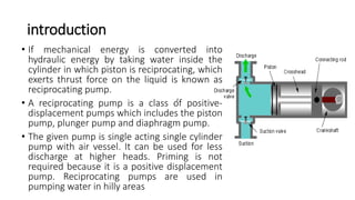
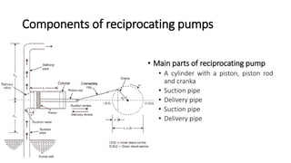
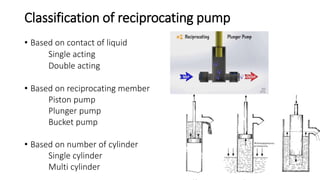

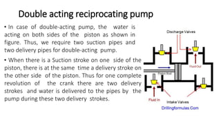
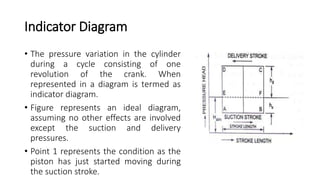


A reciprocating pump converts mechanical energy into hydraulic energy using a piston to create thrust on a liquid, classified into various types like piston, plunger, and diaphragm pumps. It can be single or double acting, with a single acting pump using one suction and delivery pipe, and a double acting pump utilizing two of each, allowing for greater efficiency. The document also discusses key components, discharge calculations, work done, slip, and pressure variations during operation represented in an indicator diagram.


