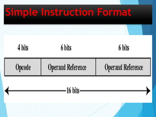
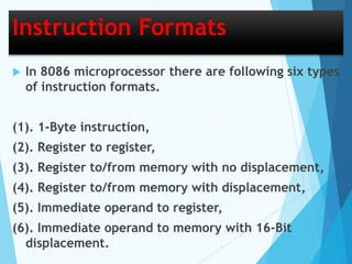
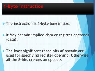
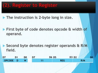
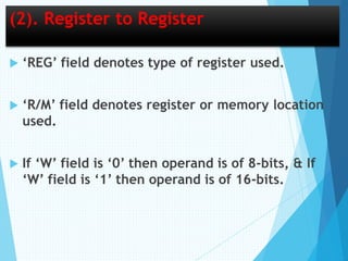
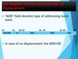
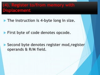
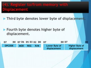
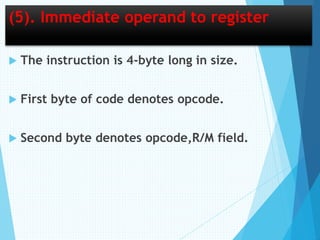
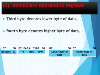
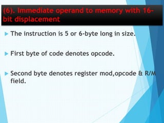
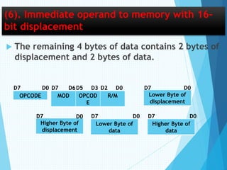
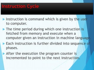
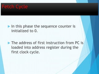
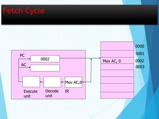
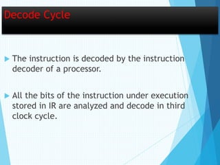
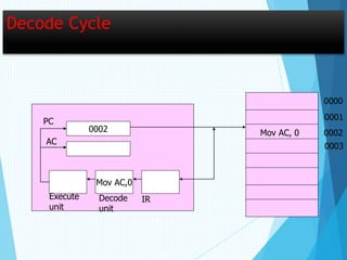
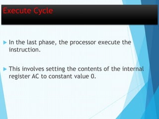
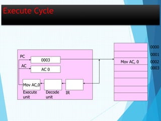
Instruction Set of 8086 Microprocessor
What is Instruction Set
 Instruction:- An instruction is a binary pattern
designed inside a microprocessor to perform a
specific function.
 The complete collection of instructions that
are understood by a CPU are known as
instruction sets.
Instruction set basics
 Opcode:- It stands for operational code. It
specifies the type of operation to be performed
by CPU. It is the first field in the machine
language instruction format.
 E.g. 08 is the opcode for instruction “MOV X,Y”.
 Operand:- We can also say it as data on which
operation should act. operands may be register
values or memory values. The CPU executes the
instructions using information present in this
field. It may be 8-bit data or 16-bit data.
Instruction set basics
 Assembler:- it converts the instruction into
sequence of binary bits, so that this bits can be
read by the processor.
 Mnemonics:- these are the symbolic codes for
either instructions or commands to perform a
particular function.
 E.g. MOV, ADD, SUB etc.
Simple Instruction Format
Instruction Formats
 In 8086 microprocessor there are following six types
of instruction formats.
(1). 1-Byte instruction,
(2). Register to register,
(3). Register to/from memory with no displacement,
(4). Register to/from memory with displacement,
(5). Immediate operand to register,
(6). Immediate operand to memory with 16-Bit
displacement.
1-Byte instruction
 The instruction is 1-byte long in size.
 It May contain implied data or register operands
(data).
 The least significant three bits of opcode are
used for specifying register operand. Otherwise
all the 8-bits creates an opcode.
(2). Register to Register
 The instruction is 2-byte long in size.
 First byte of code denotes opcode & width of
operand.
 Second byte denotes register operands & R/M
field.
OPCODE D W 11 REG R/M
D7 D0D1 D7 D5 D2 D0D6 D3
(2). Register to Register
 ‘REG’ field denotes type of register used.
 ‘R/M’ field denotes register or memory location
used.
 If ‘W’ field is ‘0’ then operand is of 8-bits, & If
‘W’ field is ‘1’ then operand is of 16-bits.
(3). Register to/from memory with no
Displacement
 The instruction is 2-byte long in size.
 First byte of code denotes opcode & width of
operand.
 Second byte denotes mod,register operands &
R/M field.
(3). Register to/from memory with no
Displacement
 ‘MOD’ field denotes type of addressing mode
used.
 In case of no displacement the MOD=00
OPCODE W MOD REG R/M
D7 D7 D6D0D1 D0D2D5 D3
(4). Register to/from memory with
Displacement
 The instruction is 4-byte long in size.
 First byte of code denotes opcode.
 Second byte denotes register mod,register
operands & R/M field.
(4). Register to/from memory with
Displacement
 Third byte denotes lower byte of displacement.
 Fourth byte denotes higher byte of
displacement.
OPCODE MOD REG R/M
D7 D0 D0D7 D6 D2D3D5
Lower Byte of
displacement
Higher Byte of
displacement
D7 D0 D0D7
(5). Immediate operand to register
 The instruction is 4-byte long in size.
 First byte of code denotes opcode.
 Second byte denotes opcode,R/M field.
(5). Immediate operand to register
 Third byte denotes lower byte of data.
 fourth byte denotes higher byte of data.
OPCODE W 11 REG R/M
D0
Lower Byte of
data
Higher Byte of
data
D7 D7 D6D5 D3 D0D2 D0D7 D0D7
(6). Immediate operand to memory with 16-
bit displacement
 The instruction is 5 or 6-byte long in size.
 First byte of code denotes opcode.
 Second byte denotes register mod,opcode & R/M
field.
(6). Immediate operand to memory with 16-
bit displacement
 The remaining 4 bytes of data contains 2 bytes of
displacement and 2 bytes of data.
OPCODE MOD OPCOD
E
R/M
D0
Lower Byte of
displacement
D7 D7 D6D5 D3 D2 D0D7D0
Higher Byte of
displacement
Lower Byte of
data
Higher Byte of
data
D7 D0D7D7 D0D0
Instruction Cycle
 Instruction is command which is given by the user
to computer.
 The time period during which one instruction is
fetched from memory and execute when a
computer given an instruction in machine language.
 Each instruction is further divided into sequence of
phases.
 After the execution the program counter is
incremented to point to the next instruction.
Phases
 Fetch an instruction from memory.
 Decode the instruction.
 Execute the instruction.
Fetch Cycle
 In this phase the sequence counter is
initialized to 0.
 The address of first instruction from PC is
loaded into address register during the
first clock cycle.
Fetch Cycle
0002
Mov AC,0
Mov AC, 0
0000
0001
0002
0003
IRDecode
unit
Execute
unit
PC
AC
Decode Cycle
 The instruction is decoded by the instruction
decoder of a processor.
 All the bits of the instruction under execution
stored in IR are analyzed and decode in third
clock cycle.
Decode Cycle
0002
Mov AC,0
0000
0001
0002
0003
PC
AC
IRDecode
unit
Execute
unit
Mov AC, 0
Execute Cycle
 In the last phase, the processor execute the
instruction.
 This involves setting the contents of the internal
register AC to constant value 0.
Execute Cycle
0003
AC 0
Mov AC,0
Mov AC, 0
0000
0001
0002
0003
IRDecode
unit
Execute
unit
PC
AC
Thank
You

8086 Microprocessor

  • 1.
    Instruction Set of8086 Microprocessor
  • 2.
    What is InstructionSet  Instruction:- An instruction is a binary pattern designed inside a microprocessor to perform a specific function.  The complete collection of instructions that are understood by a CPU are known as instruction sets.
  • 3.
    Instruction set basics Opcode:- It stands for operational code. It specifies the type of operation to be performed by CPU. It is the first field in the machine language instruction format.  E.g. 08 is the opcode for instruction “MOV X,Y”.  Operand:- We can also say it as data on which operation should act. operands may be register values or memory values. The CPU executes the instructions using information present in this field. It may be 8-bit data or 16-bit data.
  • 4.
    Instruction set basics Assembler:- it converts the instruction into sequence of binary bits, so that this bits can be read by the processor.  Mnemonics:- these are the symbolic codes for either instructions or commands to perform a particular function.  E.g. MOV, ADD, SUB etc.
  • 5.
  • 6.
    Instruction Formats  In8086 microprocessor there are following six types of instruction formats. (1). 1-Byte instruction, (2). Register to register, (3). Register to/from memory with no displacement, (4). Register to/from memory with displacement, (5). Immediate operand to register, (6). Immediate operand to memory with 16-Bit displacement.
  • 7.
    1-Byte instruction  Theinstruction is 1-byte long in size.  It May contain implied data or register operands (data).  The least significant three bits of opcode are used for specifying register operand. Otherwise all the 8-bits creates an opcode.
  • 8.
    (2). Register toRegister  The instruction is 2-byte long in size.  First byte of code denotes opcode & width of operand.  Second byte denotes register operands & R/M field. OPCODE D W 11 REG R/M D7 D0D1 D7 D5 D2 D0D6 D3
  • 9.
    (2). Register toRegister  ‘REG’ field denotes type of register used.  ‘R/M’ field denotes register or memory location used.  If ‘W’ field is ‘0’ then operand is of 8-bits, & If ‘W’ field is ‘1’ then operand is of 16-bits.
  • 10.
    (3). Register to/frommemory with no Displacement  The instruction is 2-byte long in size.  First byte of code denotes opcode & width of operand.  Second byte denotes mod,register operands & R/M field.
  • 11.
    (3). Register to/frommemory with no Displacement  ‘MOD’ field denotes type of addressing mode used.  In case of no displacement the MOD=00 OPCODE W MOD REG R/M D7 D7 D6D0D1 D0D2D5 D3
  • 12.
    (4). Register to/frommemory with Displacement  The instruction is 4-byte long in size.  First byte of code denotes opcode.  Second byte denotes register mod,register operands & R/M field.
  • 13.
    (4). Register to/frommemory with Displacement  Third byte denotes lower byte of displacement.  Fourth byte denotes higher byte of displacement. OPCODE MOD REG R/M D7 D0 D0D7 D6 D2D3D5 Lower Byte of displacement Higher Byte of displacement D7 D0 D0D7
  • 14.
    (5). Immediate operandto register  The instruction is 4-byte long in size.  First byte of code denotes opcode.  Second byte denotes opcode,R/M field.
  • 15.
    (5). Immediate operandto register  Third byte denotes lower byte of data.  fourth byte denotes higher byte of data. OPCODE W 11 REG R/M D0 Lower Byte of data Higher Byte of data D7 D7 D6D5 D3 D0D2 D0D7 D0D7
  • 16.
    (6). Immediate operandto memory with 16- bit displacement  The instruction is 5 or 6-byte long in size.  First byte of code denotes opcode.  Second byte denotes register mod,opcode & R/M field.
  • 17.
    (6). Immediate operandto memory with 16- bit displacement  The remaining 4 bytes of data contains 2 bytes of displacement and 2 bytes of data. OPCODE MOD OPCOD E R/M D0 Lower Byte of displacement D7 D7 D6D5 D3 D2 D0D7D0 Higher Byte of displacement Lower Byte of data Higher Byte of data D7 D0D7D7 D0D0
  • 18.
    Instruction Cycle  Instructionis command which is given by the user to computer.  The time period during which one instruction is fetched from memory and execute when a computer given an instruction in machine language.  Each instruction is further divided into sequence of phases.  After the execution the program counter is incremented to point to the next instruction.
  • 19.
    Phases  Fetch aninstruction from memory.  Decode the instruction.  Execute the instruction.
  • 20.
    Fetch Cycle  Inthis phase the sequence counter is initialized to 0.  The address of first instruction from PC is loaded into address register during the first clock cycle.
  • 21.
    Fetch Cycle 0002 Mov AC,0 MovAC, 0 0000 0001 0002 0003 IRDecode unit Execute unit PC AC
  • 22.
    Decode Cycle  Theinstruction is decoded by the instruction decoder of a processor.  All the bits of the instruction under execution stored in IR are analyzed and decode in third clock cycle.
  • 23.
  • 24.
    Execute Cycle  Inthe last phase, the processor execute the instruction.  This involves setting the contents of the internal register AC to constant value 0.
  • 25.
    Execute Cycle 0003 AC 0 MovAC,0 Mov AC, 0 0000 0001 0002 0003 IRDecode unit Execute unit PC AC
  • 26.