


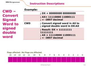
![Instruction Descriptions
16
8086 Microprocessor
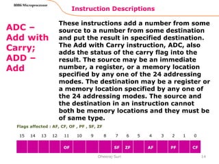
ADC –
Add with
Carry;
ADD –
Add
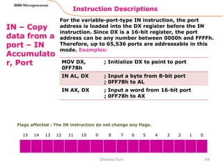
Examples(CODING)(continued):
Dheeraj Suri
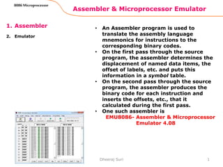
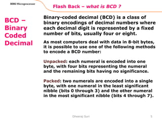
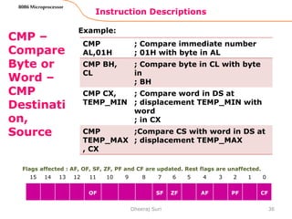
Flags affected : AF, CF, OF , PF , SF, ZF
15 14 13 12 11 10 9 8 7 6 5 4 3 2 1 0
OF SF ZF AF PF CF
ADD DX, [SI] ; Add word from memory at
offset [SI] in DS to contents
of DX
ADC AL,
PRICES[BX]
;ADD byte from effective
address ;PRICES[BX] plus
carry status to ;contents of
AL
ADD
PRICES[BX],AL
;Add contents of AL to
contents
; of memory location at
effective
; address PRICES[BX]](https://image.slidesharecdn.com/microprocessor8086instructiondescription-151224110457/85/Microprocessor-8086-instruction-description-16-320.jpg)


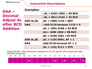
![Instruction Descriptions
22
8086 Microprocessor
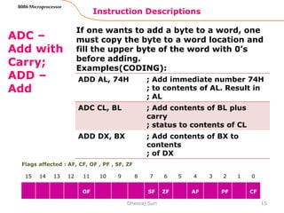
AND –
AND
correspon
ding Bits
of Two
operands
- AND
Destinati
on,
Source
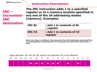
EXAMPLES(CODING):
Dheeraj Suri
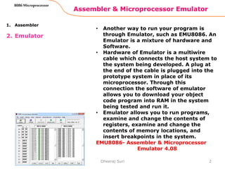
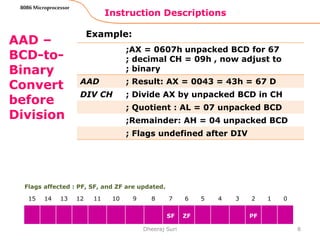
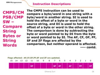
Flags affected : PF, SF, and ZF are updated by AND. But CF and OF are both 0. AF is
undefined.
15 14 13 12 11 10 9 8 7 6 5 4 3 2 1 0
0 SF ZF PF 0
; AND word in DS at offset[SI]
; with word in CX register
AND
CX,[SI]
; Result in CX Register
AND BH, CL ; AND byte in CL with byte in BH
; Result in BH
; AND words in BX with
immediate
AND BX,
00FFH
; 00FFH. Masks upper byte,
leaves lower byte unchanged.](https://image.slidesharecdn.com/microprocessor8086instructiondescription-151224110457/85/Microprocessor-8086-instruction-description-22-320.jpg)


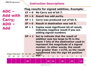
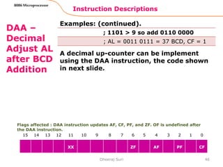
![CALL – Call a procedure
27
8086 Microprocessor
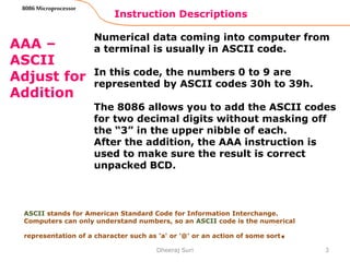
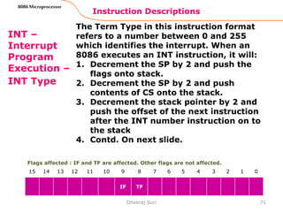
Examples(continued):
Dheeraj Suri
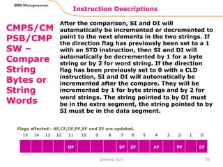
CALL SMART-
DIVIDE
;A direct call to another segment – far or
;intersegment call. SMART-DIVIDE is the name
;of the procedure. The procedure must be
;declared far with SMART_DIVIDE PROC FAR
;at its start. The Assembler will determine the
;code segment base for the segment which
;contains the procedure and the offset of the
;start of the procedure. It will put these values
;in as part of the instruction code.
CALL
DWORD
PTR[BX]
; An indirect call to another segment – far or
;intersegment call. New Values for CS and IP
;are fetched from four memory locations in DS.
;The new value for CS is fetched from [BX] and
;[BX+1]; the new IP is fetched from [BX+2]
;and [BX+3].](https://image.slidesharecdn.com/microprocessor8086instructiondescription-151224110457/85/Microprocessor-8086-instruction-description-27-320.jpg)


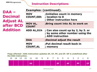
![Instruction Descriptions
37
8086 Microprocessor
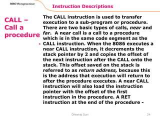
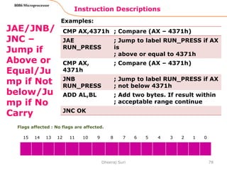
CMP –
Compare
Byte or
Word –
CMP
Destinati
on,
Source
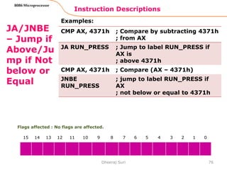
Example:
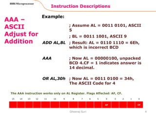
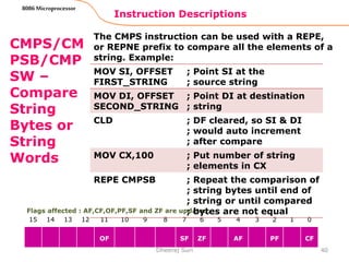
Note: The Compare instructions are often used
with the conditional Jump instruction. For
Example:
Dheeraj Suri
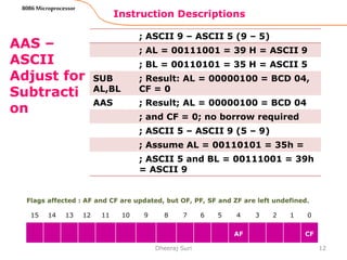
Flags affected : AF, OF, SF, ZF, PF and CF are updated. Rest flags are unaffected.
15 14 13 12 11 10 9 8 7 6 5 4 3 2 1 0
OF SF ZF AF PF CF
CMP
PRICES[BX],
49H
; Compare immediate 49H
; with byte at offset [BX] in
; array PRICES
CMP BX, CX
JAE TARGET ; Jump to target if BX is above
or
; equal to CX](https://image.slidesharecdn.com/microprocessor8086instructiondescription-151224110457/85/Microprocessor-8086-instruction-description-37-320.jpg)


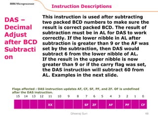

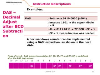


![Instruction Descriptions
53
8086 Microprocessor
DEC –
Decrement
Destination
Register or
Memory –
DEC
Destination
Examples:
Dheeraj Suri
Flags affected : AF, OF, PF, SF, and ZF are updated, but CF is not affected.
15 14 13 12 11 10 9 8 7 6 5 4 3 2 1 0
OF SF ZF AF PF
DEC CL ; Subtract 1 from contents of
; CL register
DEC BP ; Subtract 1 from contents of BP
; register
DEC BYTE
PTR[BX]
; Subtract 1 from byte at offset
[BX] in DS. The BYTE PTR directive
is necessary to tell the
; assembler to put in the correct
; code for decrementing a byte in
; memory, rather than
; decrementing a word. The
; instruction essentially says,
; “Decrement the byte in memory
; pointed to by the offset in BX”](https://image.slidesharecdn.com/microprocessor8086instructiondescription-151224110457/85/Microprocessor-8086-instruction-description-53-320.jpg)
![Instruction Descriptions
54
8086 Microprocessor
DEC –
Decrement
Destination
Register or
Memory –
DEC
Destination
Examples(continued):
Dheeraj Suri
Flags affected : AF, OF, PF, SF, and ZF are updated, but CF is not affected.
15 14 13 12 11 10 9 8 7 6 5 4 3 2 1 0
OF SF ZF AF PF
DEC WORD
PTR[BP]
;Subtract 1 from a word at offset
; [BP] in SS. The WORD PTR
; directive tells the assembler to
; put in the code for decrementing
; a word pointed to by the
; contents of BP. An offset in BP
; will be added to the SS register
; contents to produce the physical
; address
DEC
TOMATO_CAN
_COUNT
;Subtract 1 from byte or word
; named TOMATO_CAN_COUNT in
DS.](https://image.slidesharecdn.com/microprocessor8086instructiondescription-151224110457/85/Microprocessor-8086-instruction-description-54-320.jpg)

![Instruction Descriptions
56
8086 Microprocessor
DIV –
Unsigned
Divide –
DIV source
Examples(syntax):
Dheeraj Suri
Flags affected : The CF, OF, SF, ZF, AF, and PF flags are undefined
DIV BL ;Divide word in AX by byte in BL.
;Quotient in AL, remainder in AH
DIV CX ;Divide doubleword in DX and AX
; by word in CX. Quotient in AX,
Remainder in DX.
DIV
SCALE[BX]
;AX/(byte at effective address
SCALE[BX] if SCALE[BX] is of type
byte or (DX and AX)/(word at
effective address SCALE[BX]) if
SCALE[BX] is of type word.
15 14 13 12 11 10 9 8 7 6 5 4 3 2 1 0
IF TF](https://image.slidesharecdn.com/microprocessor8086instructiondescription-151224110457/85/Microprocessor-8086-instruction-description-56-320.jpg)


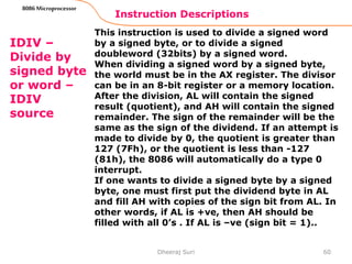

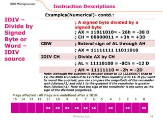
![Instruction Descriptions
62
8086 Microprocessor
IDIV –
Divide by
Signed
Byte or
Word –
IDIV
source
Examples(Coding):
Dheeraj Suri
Flags affected : All flags are undefined after a IDIV.
15 14 13 12 11 10 9 8 7 6 5 4 3 2 1 0
XX XX XX XX XX XX XX XX XX
IDIV BL ; Signed word in AX/signed byte
; in BL
IDIV BP ; Signed double-word in DX and
AX/signed word
IDIV BYTE
PTR[BX]
; AX/byte at offset [BX] in DS
MOV AL,
DIVIDEND
; position byte dividend
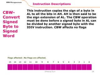
CBW ; Extend sign of AL into AH
IDIV
DIVISOR
; Divide by byte divisor](https://image.slidesharecdn.com/microprocessor8086instructiondescription-151224110457/85/Microprocessor-8086-instruction-description-62-320.jpg)


![Instruction Descriptions
82
8086 Microprocessor
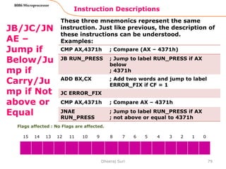
JCXZ –
Jump if
CX
register
is Zero
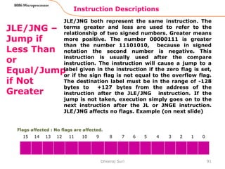
This instruction will cause a jump to a label given in
the instruction if the CX register contains all 0’s,
execution will simply proceed to the next instruction.
Note that this instruction doesnot look at the zero flag
when it decides whether to jump or not. The
destination label for this instruction must be in the
range of -128 to +127 bytes from the address of the
instruction after JCXZ instruction. JCXZ affects no
flags. Example:
Dheeraj Suri
Flags affected : No flags are affected.
15 14 13 12 11 10 9 8 7 6 5 4 3 2 1 0
JCXZ SKIP_LOOP ; IF CX = 0, skip the process
NXT: SUB [BX], 07h ; Subtract 7 from data value
INC BX ; point to next value
LOOP NXT ; Loop until CX = 0
SKIP_LOOP: ; Next instruction](https://image.slidesharecdn.com/microprocessor8086instructiondescription-151224110457/85/Microprocessor-8086-instruction-description-82-320.jpg)


![Instruction Descriptions
95
8086 Microprocessor
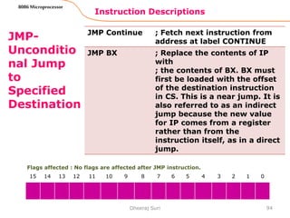
JMP-
Unconditio
nal Jump
to
Specified
Destination
Dheeraj Suri
Flags affected : No flags are affected after JMP instruction.
15 14 13 12 11 10 9 8 7 6 5 4 3 2 1 0
JMP WORD
PTR[BX]
; Replace IP with a word to by
BX ; in DS. This is an indirect
near jump.
JMP DWORD
PTR[SI]
; Replace IP with a word
pointed to by SI in DS. Replace
CS with a word pointed to by
SI + 2 in DS. This is an indirect
far jump.](https://image.slidesharecdn.com/microprocessor8086instructiondescription-151224110457/85/Microprocessor-8086-instruction-description-95-320.jpg)


The document discusses assembler programs and emulators for the 8086 microprocessor. It provides the following information: - An assembler program translates assembly language mnemonics into binary machine codes. It performs two passes through the source code to calculate offsets and produce the final binary output. - An emulator is a combination of hardware and software that allows programs to run by downloading object code into RAM and simulating the microprocessor. Emulators like EMU8086 allow examining and modifying registers and memory. - Instructions like AAA, AAS, AAM, and AAD are used to adjust results of numeric operations involving ASCII-encoded digits to produce the proper unpacked Binary Coded Decimal values.