Downloaded 122 times


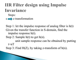
![We wish to derive a linear phase IIR filter with real
nonzero h(n) . The impulse response must be
symmetric
M
[ /2]
k n
h n A A
( )
2 cos( )
0
1
2 ( 1/ 2)
1
k
k
M
where are real and denotes the integer part
k A[ / 2] M](https://image.slidesharecdn.com/pd-141030022444-conversion-gate01/85/filter-design-15-320.jpg)
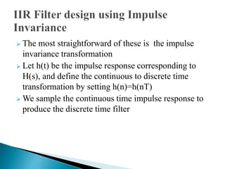
![ with corresponding transform
N
H z H z
( ) ( )
where
Hence
1
k
0
k N
/2
k
j
k /
N N
A e z
(1 )
H z
k j k N
2 / 1
( )
k
1
e z
sin
/ 2
' ( )
( 1)/2 which has a linear phase
sin[( / / 2)]
j T N
k k
TN
H A e
k N T
](https://image.slidesharecdn.com/pd-141030022444-conversion-gate01/85/filter-design-17-320.jpg)
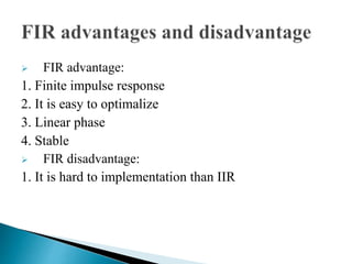
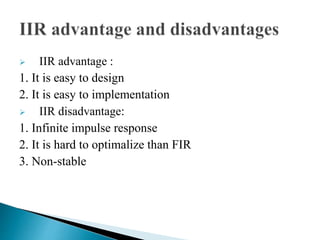


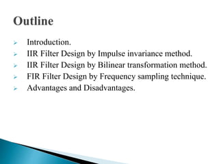
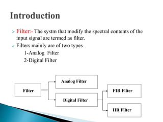
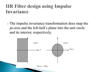
This document discusses different methods for designing digital filters, including FIR and IIR filters. It describes the impulse invariance and bilinear transformation methods for designing IIR filters, as well as frequency sampling techniques for FIR filter design. Advantages and disadvantages of FIR and IIR filters are provided. The key steps of the bilinear transformation method are outlined, along with discussions of designing linear phase IIR filters and specifying filters based on desired magnitude responses.