The document provides an introduction to digital signal processing (DSP) algorithms and architecture. It discusses key topics including DSP systems, sampling processes, discrete Fourier transforms, linear time-invariant systems, digital filters, and decimation and interpolation. The learning objectives are to understand these fundamental DSP concepts and use MATLAB as an analysis and design tool. The contents cover DSP systems, sampling, the discrete Fourier transform and fast Fourier transform, linear time-invariant systems, digital filters, and decimation and interpolation. Textbooks and references on the subject are also listed.


![FIND THE MAGNITUDE AND PHASE RESPONSE OFAN FIR
FILTER REPRESENTED BY THE DIFFERENCE EQUATION
Y(N)= 0.5 X(N) + 0.5 X(N-1)
Y (n) = 0.5 x(n) + 0.5 x(n-1)
h (n) = 0.5 δ(n) + 0.5 δ(n-1)
= [0.5 0.5]
H (Z) = 0.5+0.5Z-1
H (e jθ)= 0.5+0.5 e-jθ
= 0.5+0.5 cos θ -j0.5 sin θ
= 0.5 (1+ cos θ) -j0.5 sin θ
= [0.5*2* cos2 (θ/2)]-j[0.5*2* sin (θ/2)* cos (θ/2)]
H (e jθ)= cos2 (θ/2) -j[sin (θ/2)* cos (θ/2)]
E C E , G E C R 32](https://image.slidesharecdn.com/module1dspa-240308095913-0f13883f/75/Module1_dsffffffffffffffffffffgggpa-pptx-32-2048.jpg)


![3. Let x(n)=[3 2 2 4 1 0 –3 –2 –1 0 2 3] be
decimated with a factor of 2. Let the filtered sequence
be w(n)=[2.1 2 3.9 1.5 0.1 –2.9 –2 –1.1 0.1 1.9 2.9].
Obtain the decimated sequence y(m)
Sequence y(m) can be obtained by dropping every
alternative sample of w (n). y (m) = [2 1.5 -2.9
-1.1 1.9]
E C E , G E C R 44](https://image.slidesharecdn.com/module1dspa-240308095913-0f13883f/75/Module1_dsffffffffffffffffffffgggpa-pptx-44-2048.jpg)

![4. LET X(N)= [0 3 6 9 12] BE INTERPOLATED WITH L=3. IF THE
FILTER COEFFICIENTS OF THE FILTERS ARE BK=[1/3 2/3 1 2/3 1/3],
OBTAIN THE INTERPOLATED SEQUENCE
After inserting zeros,
w (m) = [0 0 0 3 0 0 6 0 0 9 0 0 12]
bk=[1/3 2/3 1 2/3 1/3] We have,
y(m)= Σ bk w(m-k) = b-2 w(m+2)+ b-1 w(m+1)+ b0 w(m)+ b1 w(m-1)+ b2 w(m-2)
Substituting the values of m, we get
y(0)= b-2 w(2)+ b-1 w(1)+ b0 w(0)+ b1 w(-1)+ b2 w(-2)= 0 y(1)= b-2 w(3)+ b-1 w(2)+
b0 w(1)+ b1 w(0)+ b2 w(-1)=1 y(2)= b-2 w(4)+ b-1 w(3)+ b0 w(2)+ b1 w(1)+ b2
w(0)=2
Similarly we get the remaining samples as,
y (n) = [ 0 1 2 3 4 5 6 7 8 9 10 11 12]
E C E , G E C R 46](https://image.slidesharecdn.com/module1dspa-240308095913-0f13883f/75/Module1_dsffffffffffffffffffffgggpa-pptx-46-2048.jpg)
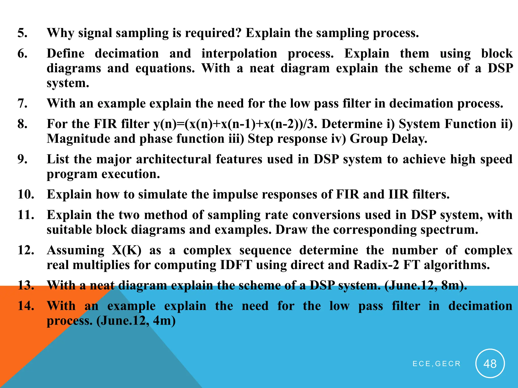
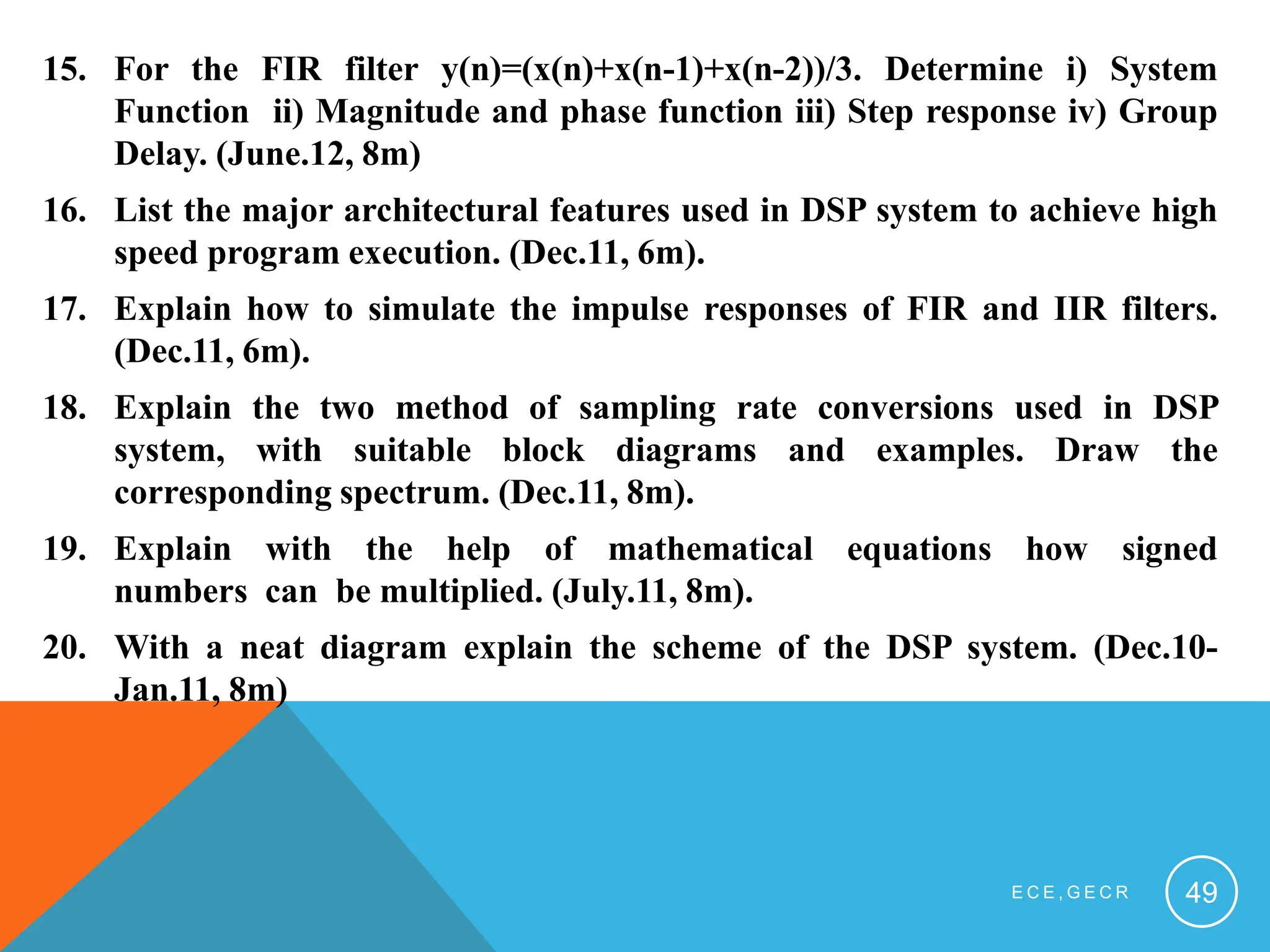
![QUESTIONS
1. Explain with the help of mathematical equations how signed
numbers can be multiplied. The sequence x(n) = [3,2,-2,0,7].It is
interpolated using interpolation sequence bk=[0.5,1,0.5] and the
interpolation factor of 2. Find the interpolated sequence y(m).
2. An analog signal is sampled at the rate of 8KHz. If 512 samples of this
signal are used to compute DFT X(k) determine the analog and digital
frequency spacing between adjacent X(k0 elements. Also, determine
analog and digital frequencies corresponding to k=60.
3. With a neat diagram explain the scheme of the DSP system.
4. What is DSP? What are the important issues to be considered in designing
and implementing a DSP system? Explain in detail.
E C E , G E C R 47](https://image.slidesharecdn.com/module1dspa-240308095913-0f13883f/75/Module1_dsffffffffffffffffffffgggpa-pptx-47-2048.jpg)