Downloaded 132 times

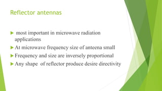
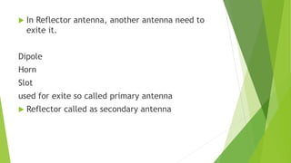
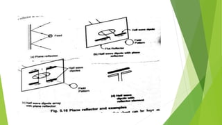
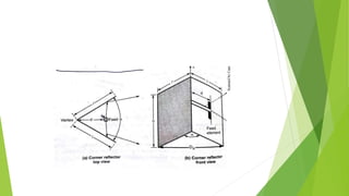
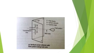
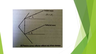
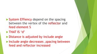
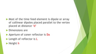

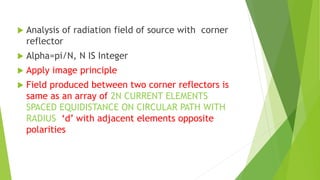
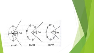
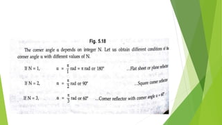
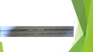
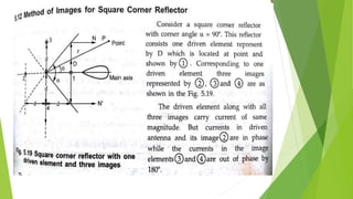


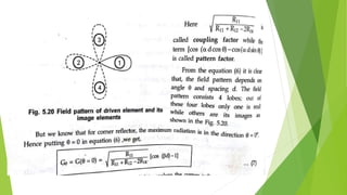


Reflector antennas use a primary feed antenna and a reflecting surface to direct the radio waves in a desired direction. The most common types of reflector antennas are flat sheet, corner, and parabolic reflectors. A corner reflector uses two flat surfaces joined at an angle, typically 90 degrees, to concentrate the radiation in the forward direction. The analysis of a corner reflector models the feed antenna and its multiple images formed by the reflector surfaces as an array of current elements on a circular path, which reinforces the radiation in the desired direction. Properly designing the dimensions and spacing of the feed from the reflector vertex results in a corner reflector with a gain of around 9 dB or more compared to a half-